Introduction
The chest X-ray remains an important tool in the preoperative and postoperative evaluation of a pacemaker, implantable cardioverter-defibrillator (ICD) or cardiac resynchronization therapy (CRT) system. Additionally, the chest radiograph is essential when assessing the integrity of a pacing or ICD system. Both a posteroanterior (PA) and a lateral view should be obtained. A systematic approach should be employed, evaluating various anatomic and device components in an orderly fashion.1–3
Preoperatively, the presence of clips, wires, prosthetic valves, and other hardware can provide clues to prior cardiac or thoracic surgery, which may be important when planning the operative procedure. After implantation of the pacing, ICD or CRT system, both PA and lateral radiographs should be obtained to confirm correct lead position(s) (Fig. 11.1) and to note potential surgical complications such as pneumothorax, pleural effusion, and pericardial effusion. (In addition, an oblique film may at times be helpful to determine more precisely the location of a coronary venous lead.) A chest radiograph should be performed as part of most device troubleshooting assessments. Table 11.1 provides a systematic approach to assessment of the chest radiograph of the patient with a device. Comparison with any previous radiographs is frequently useful. As part of the “total” care of the patient, inspection of the entire radiograph should be carried out, including: bony structures, aorta, cardiac silhouette, trachea, diaphragm, and lung fields.
Table 11.1 Systematic approach to radiographic assessment of pacemakers and ICDs.
| Systematic approach | Clinical considerations |
| Determine pulse generator site | Any suggestion that there has been a significant shift from intended position, e.g., displaced generator, could be associated with lead dislodgment or Twiddler’s |
| Determine pulse generator manufacturer, polarity, and model if possible | Radiographic identifiers allow determination of manufacturer – helpful if the patient comes without ID card |
| Inspect the connector block | Polarity of pulse generator should be determined and compared with polarity of leads Is connector pin(s) completely through connector block? Loose connection could explain intermittent or complete failure to output or intermittent failure to capture |
| Consider venous route utilized | Especially important if a pacemaker system revision is being considered, i.e., can the same venous route be accessed and how many leads are already placed in a single vein |
| Determine lead polarity | Does lead polarity match pulse generator polarity or has some type of adaptor been used to allow the system hardware combination? |
| Determine lead position | Determine where the lead was positioned, i.e., for the ventricular lead, is it in the apex, outflow tract, septal position, coronary sinus?; for the atrial lead, is it atrial appendage, lateral wall, septal position, coronary sinus? |
| Does lead position appear radiographically acceptable? | Inadequate lead position may explain failure to capture and/or sense. Compare current X-ray to previous X-ray if possible. Is ventricular lead redundancy or “slack” adequate; is atrial “J” adequate? |
| Inspect entire length of lead for integrity, i.e., fracture, compression, crimp, etc. | Intermittent or complete failure to capture/sense and/or output could be secondary to lead conductor coil fracture or loss of insulation integrity. Attempt to follow each lead along its course assessing the conductor coil. Also inspect for any “crimping” of the lead as it passes under the clavicle |
| Any other chest X-ray abnormality that is potentially related | For a recent implant, be certain there is no pneumothorax or hemopneumothorax. For the ICD patient with a change in defibrillation thresholds, whether acute or chronic, remember that a pneumothorax can be responsible for alterations in DFT |
| If no abnormality is appreciated radiographically but there is a clinical abnormality – reassess the chest X-ray in a problem-oriented fashion | As an example, if the patient has intermittent failure to output, the differential diagnosis would include a problem with the connector pin, i.e., loose setscrew, or conductor coil fracture. Go back once again and inspect these elements of the pacing system |
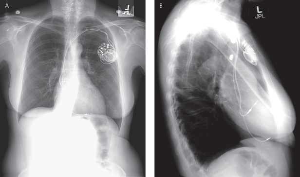
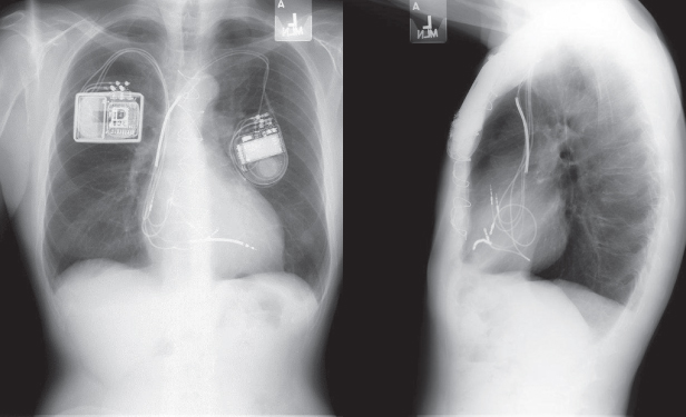
Fig. 11.1 Posteroanterior (A) and lateral (B) chest radiographs of a dual-chamber pacing system. The pulse generator is located in a left prepectoral position. The position of both atrial and ventricular leads is acceptable. The “J” on the atrial lead is adequate, and is best seen in the lateral view. The ventricular lead is not positioned in a true apical position but is well seated with adequate slack. In a true apical position, it would be seen closer to the sternum in the lateral view.
(Reproduced with permission from Hayes DL. Radiography of implantable arrhythmia management devices. In: Kusumoto F, Goldschlager N, eds. Cardiac Pacing for the Clinician. New York: Springer Science + Business Media, 2007.)
Pulse Generators
Most pulse generators are placed in a prepectoral location, inferior to the clavicle and medial to the axilla. At one time, many implants in children as well as many early ICDs were placed in an abdominal position, either below or anterior to the rectus muscle. If the pulse generator is located in an abdominal position, radiographic evaluation requires an AP radiograph of the abdomen as well as a PA and lateral chest radiograph.
In some patients a subpectoral position may be used in lieu of the more common prepectoral location but these positions are difficult to differentiate radiographically.
The retromammary position was once advocated for a better cosmetic result. However, given the size of contemporary devices, this surgical approach is rarely necessary and long term is more difficult because of the more involved operative techniques required (Fig. 11.2). True axillary position has also been used in an effort to obtain a better cosmetic result, but due to the somewhat more complex implant technique as well as potential discomfort of the pulse generator in this position, use of this location is uncommon.
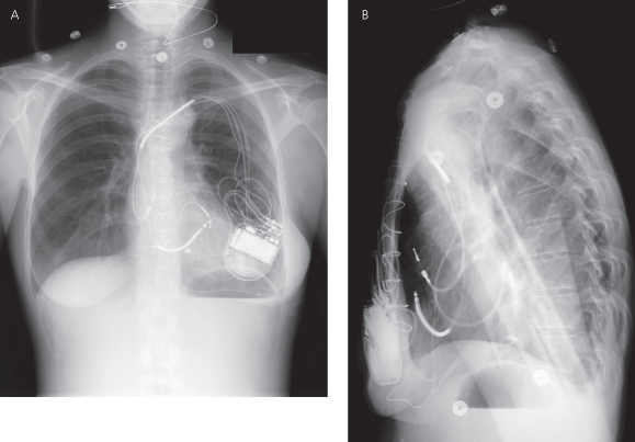
Fig. 11.2 (A) Posteroanterior and (B) lateral chest radiographs of a cardiac resynchronization therapy device (CRT-D), system with the pulse generator located in a retromammary position. Note that the right ventricular coil is in a low outflow/high septal position. The preferred view for distinguishing outflow tract and coronary sinus (CS) positions is the lateral view. In the lateral film, the right ventricular coil is just behind the sternum, whereas the CS leads wraps posteriorly in the CS, closer to the spine.
(Reproduced with permission from Hayes DL. Radiography of implantable arrhythmia management devices. In: Kusumoto F, Goldschlager N, eds. Cardiac Pacing for the Clinician. New York: Springer Science + Business Media, 2007.)
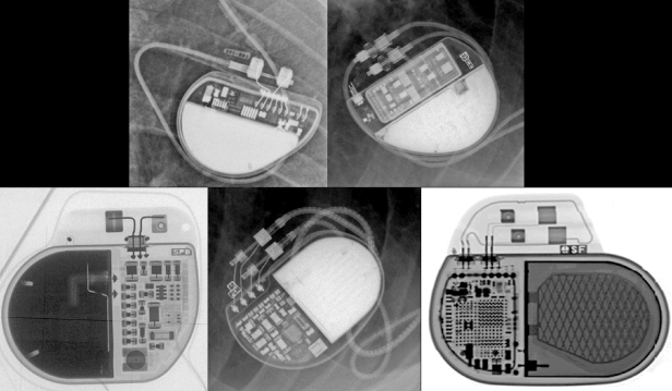
The pulse generator manufacturer and model can usually be identified from the chest radiograph. At one time, unique shape, size, and internal circuitry pattern were sufficient to identify a manufacturer and model. Although this no longer holds true, all current devices have a radiopaque code identifying the manufacturer and model of the device or some alpha-numeric code by which the company’s technical services group can identify the “family” of devices (Fig. 11.3, Table 11.2). After identification of the manufacturer, the technical support division of that manufacturer can identify the device and should be able to provide additional information obtained at the time of implant and kept on file with the pulse generator registration (leads utilized, configurations, thresholds, etc.). The relationship of redundant, coiled lead(s) to the generator in the pocket should be noted. It may be difficult to determine which lead is connected to the pulse generator and which lead is abandoned.
Table 11.2 Radiographic identifiers by manufacturer.
| Manufacturer | |
| Biotronik | ICDs/CRT identified with a three-part code: year of manufacture, Biotronik logo, and a two-letter code unique to each device family; pacemakers identified with a two-part code: Biotronik logo and a two-letter code unique to each device family |
| Boston Scientific (Guidant) | Letters “BOS” to identify the manufacturer followed by a three-digit number which identifies which model software application is needed to communicate with the pulse generator; three-digit number does not correlate with a device model number. Note that older devices will have the designation “GDT” for devices manufactured by Guidant Corp. |
| Medtronic | Historically used a Medtronic-identifier symbol (Medtronic “M”) followed by a unique alphanumeric identifier for each device “model.” With current generation devices the radiographic identifier signifies a broader grouping or family of Medtronic devices. With the “group” identifier, technical services can provide a list of the specific models in that grouping. |
| St. Jude Medical | Each device has an alphanumeric series that corresponds to a specific model and can be identified from the technical manuals or by calling technical services |
| Sorin/ELA | ELA devices: the letters “ELA” appear and may have an additional model code. Sorin Group/Sorin Biomedica: Current devices consist of a three letter code beginning with “S” followed by both a group and a model letter. Previous Sorin Biomedica devices may have five letters |
Fig. 11.3 Examples of radiographic identification of the pacemaker by radiographic codes embedded in the device. Upper left, Boston Scientific; upper right, St. Jude Medical; lower left, Sorin Medical; lower middle, Medtronic; lower right, Biotronik.
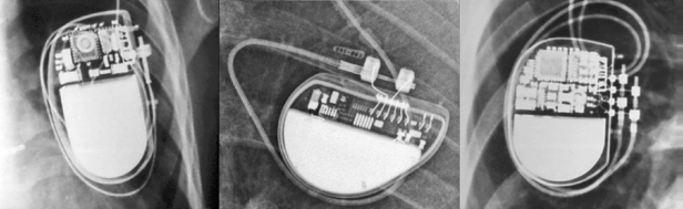
The polarity of the pulse generator should be determined. This can be ascertained by the number and type of connector pins, i.e., unipolar or coaxial bipolar. (Recognition of a bifurcated bipolar lead is also possible, although there are a declining number of these leads that remain in service; Fig. 11.4.) Most contemporary pacemakers have independently programmable polarity, so the presence of bipolar leads does not necessarily imply that the device is functioning in a bipolar configuration.
Fig. 11.4 Examples of three pulse generator polarity configurations, as described in the text. Left panel, unipolar polarity; middle panel, bipolar single-chamber pacemaker; right panel, dual-chamber bipolar configuration.
(Modified with permission from Hayes DL. Radiography of implantable arrhythmia management devices. In: Kusumoto F, Goldschlager N, eds. Cardiac Pacing for the Clinician. New York: Springer Science + Business Media, 2007.)
Migration of a pulse generator is less common with the smaller devices used today. However, comparison of previous and current radiographs for pulse generator position is useful. The clinical concern about pulse generator migration is that tension may be placed on the lead, possibly causing dislodgment or fracture. It is not possible to determine from a radiograph whether the patient is a “twiddler,” but a twisted appearance of the lead suggests Twiddler’s syndrome, be it secondary to true patient manipulation of the pulse generator (Fig. 11.5)4 or, more commonly, rotation of the pulse generator within an oversized pocket, also referred to as Reel syndrome (Fig. 11.6).5,6
Fig. 11.5 (A) PA chest radiograph and (B) close-up in a patient with marked twisting of both leads resulting in lead retraction. This appearance is consistent with twiddler’s syndrome.
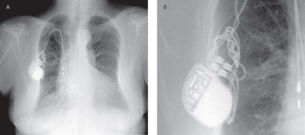
Fig. 11.6 (A) Posteroanterior radiograph from a patient following CRT-D implant. (B) Subsequent X-ray from the same patient the atrial lead and coronary sinus lead are completely retracted from the cardiac silhouette and looped or “reeled” around the pulse generator. This is a classic appearance of “Reel syndrome.”
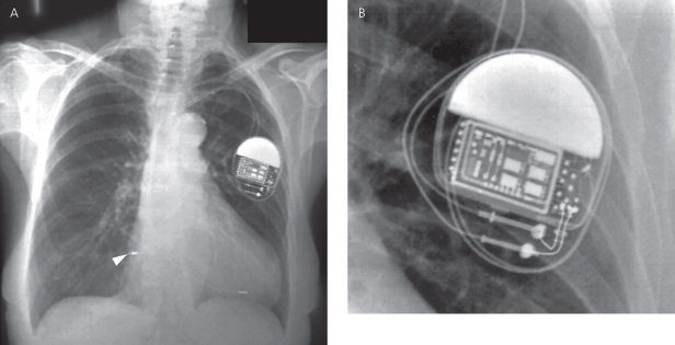
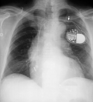
Inspection of the generator connector block should be performed. The lead connector pin should be advanced beyond the setscrew(s) in the connector block, and the screws should be in direct contact with the pin. One cause of intermittent pacing failure, failure to output and/or failure to capture, is a loose connection between the setscrews and the connector pin (Fig. 11.7).
Fig. 11.7 (A) Posteroanterior radiograph and (B) close-up view from a patient with intermittent failure to pace. Comparison of the upper and lower pins reveals that the lower of the two unipolar leads is not completely advanced. This difference is more evident on the close-up view. By convention, the lower of the two leads in the connector block is the ventricular lead, so that this patient must have had intermittent or permanent ventricular failure to output. An unrelated observation, noted by the arrowhead, is shallow positioning of the atrial lead, i.e., the “J” is much wider than 90°.
(From Hayes DL. Pacemaker radiography. In: Furman S, Hayes DL, Holmes DR Jr, eds. A Practice of Cardiac Pacing, 3rd edn. Mount Kisco, NY: Futura Publishing, 1993: 361–400, by permission of Mayo Foundation for Medical Education and Research.)
Other Types of Pulse Generators
Although some implantable devices may not be readily identifiable, patient history, review of records, and assessment of available identification cards will usually reveal the type of device that has been implanted.
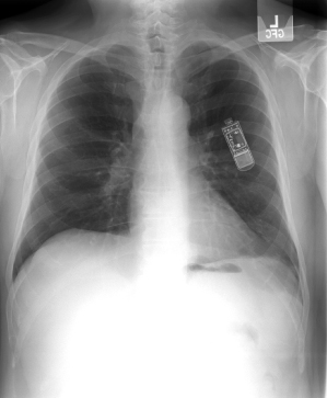
Implantable loop recorders are implanted with increasing frequency and appear as a small device usually in the pectoral region without an associated lead (Fig. 11.8).
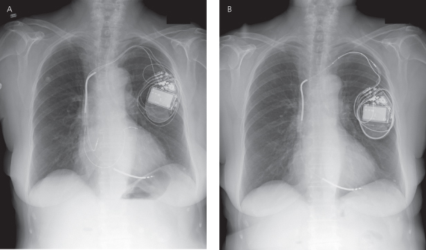
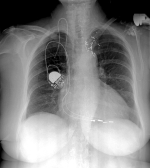
Investigational devices may be more difficult to identify but most patients involved in an investigational protocol are often able to provide specific details. Figure 11.9 demonstrates an ICD as well as an investigational device used for cardiac contractility modulation.
Fig. 11.9 Posteroanterior chest radiograph from a patient with a CRT-D device (pulse generator in left pectoral region) as well as a pulse generator on the right side. The right-sided pulse generator is an investigational device for the purpose of cardiac contractility modulation.
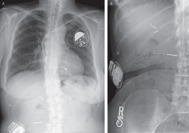
Always inspect the radiographic films for noncardiac hardware. Figure 11.10 demonstrates a patient with a pacemaker and a spinal stimulator.
Fig. 11.10 (A) Posteroanterior chest radiograph and (B) abdominal film. A dual-chamber pacemaker is present in the left prepectoral position. In addition, on the PA film, a lead and the superior portion of another pulse generator can be seen in the lower right portion of the film. On the abdominal X-ray (B) the other pulse generator, a spinal cord stimulator and associated lead, can be more easily visualized.
Leads
Lead assessment is a critical component of the radiographic assessment of a pacing and/or ICD system. Standard radiographic techniques may not clearly demonstrate lead components. At one time, higher radiographic penetration and/or coning of the radiographic field was suggested to achieve better visualization of leads. However, if the radiograph has been stored digitally it may be possible to manipulate the images to better delineate the leads. Figure 11.11 demonstrates a PA chest radiograph before and after the contrast has been altered. Unfortunately, lead-insulating materials are not visualized radiographically, and loss of insulation integrity breech is a cause of lead failure that is not uncommon. Occasionally it is possible to see what appears to be a lack of continuity of the lead surface, which may correlate with a breech in the insulation (Fig. 11.12).
Fig. 11.11 Posteroanterior chest radiographs before (A) and after (B) digital manipulation of the contrast level. By manipulating the contrast the pacemaker leads can be more easily seen in (B).
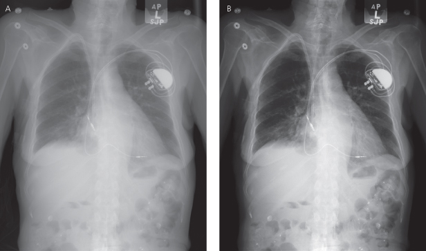
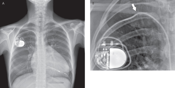
Fig. 11.12 (A) Posteroanterior chest radiograph and (B) close-up of a portion of the posteroanterior film demonstrating a disruption of the outer portion of the lead, presumably the insulation, with the appearance that the conductor coil is intact (arrowhead). In this patient, chronic pacing thresholds were considered acceptable and unchanged.
The number, types, location, and radiographic integrity of all leads should be determined after studying the PA and lateral radiographs. Unlike pulse generators, leads do not have characteristic radiopaque markers to aid in their identification; however, information regarding the type and functional status of various leads can be obtained by their radiographic appearance.
It is not uncommon for a patient to have a cardiac rhythm device implanted and have a variety of functional and abandoned leads, both epicardial, transvenous, and/or coronary venous. If additional procedures are required and lead extraction is required, it may be necessary to determine the type, position, and integrity of all leads.
Pacemaker Leads
The vast majority of contemporary pacing leads are placed transvenously, although patients may still have epicardial (myocardial) pacing wires placed after certain types of cardiac surgical repair or due to congenital cardiac anomalies. Intravascular insertion of transvenous leads is usually through either the right or left axillary, subclavian, or cephalic veins. The internal or external jugular veins have been used in the past, but should not be considered a good alternative for lead placement at this time (Fig. 11.13). Jugular vein insertion sites are usually easily identified by the lead coursing over or under the clavicle.
Fig. 11.13 Posteroanterior chest radiograph. The functional lead is placed in the subclavian vein; a portion of a much older transected second lead remains that was inserted through the right jugular vein.
(Reproduced with permission from Hayes DL. Radiography of implantable arrhythmia management devices. In: Kusumoto F, Goldschlager N, eds. Cardiac Pacing for the Clinician. New York: Springer Science + Business Media, 2007.)
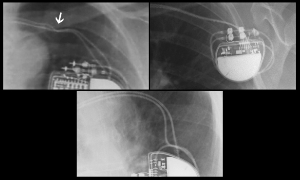
Clues as to the insertion site may be obtained from the chest radiograph by a change in the directional contour of the lead (Fig. 11.14). A more medial insertion site suggests a subclavian approach; a more lateral site suggests a cephalic or axillary approach.
Fig. 11.14 Radiographs demonstrating different venous routes for permanent lead placement. Upper left, subclavian vein placement. Note compression of the lead as it passes between the first rib and the clavicle (arrow); upper right, axillary vein placement; bottom, cephalic vein placement.
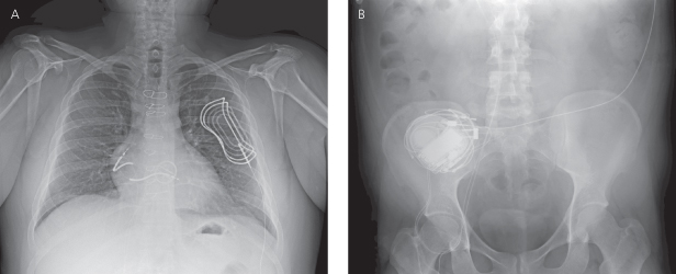
A femoral approach may occasionally be needed if access via the superior veins is not an option. An X-ray of the pelvis and abdomen is necessary to assess adequately the course and integrity of the lead (Fig. 11.15).
Fig. 11.15 (A) Posteroanterior chest radiograph and (B) abdominal film from a patient with the lead implanted via the femoral vein. The course of the defibrillation leads is through the inferior vena cava to the right atrium and right ventricular position. Also seen is an extravascular subcutaneous patch over the left heart, necessary to create a shocking vector encompassing the left ventricle.
The radiopaque conductor coil should be inspected in its entirety. There should be no discontinuity of the coil (Fig. 11.16); any kinking or sharp angulation may represent lead fracture. Special attention should be paid to the area between the first rib and the clavicle, as this is a frequent site of lead fracture (subclavian crush syndrome) (Fig. 11.17).7
Fig. 11.16 (A) Posteroanterior chest radiograph demonstrating complete separation of the conductor coil of the ventricular lead as it passes below the clavicle (upper arrow). (The lower arrow notes a suboptimally positioned atrial lead which is too shallow.). (B) In the close-up view, the arrow again notes the separation of the conductor coil.
(Reproduced with permission from Hayes DL. Radiography of implantable arrhythmia management devices. In: Kusumoto F, Goldschlager N, eds. Cardiac Pacing for the Clinician. New York: Springer Science + Business Media, 2007.)
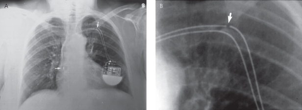
Fig. 11.17 Posteroanterior chest radiograph. Pacing leads entering via the subclavian vein. Note indentation (arrow) of the lead as it passes under the clavicle, signifying compression of the lead.
(Reproduced with permission from Hayes DL. Radiography of implantable arrhythmia management devices. In: Kusumoto F, Goldschlager N, eds. Cardiac Pacing for the Clinician. New York: Springer Science + Business Media, 2007.)
Indentations caused by ligatures compressing the insulating material of a lead (Fig. 11.18) do not usually have any clinical significance. Such indentations do not imply the presence of lead damage, although it is possible to affect lead integrity with excessively tight ligatures placed around the sleeve.


