Radiation Safety in the Cardiac Catheterization Laboratory
BACKGROUND
Radiation-induced injury is a well-recognized risk associated with invasive procedures in cardiac catheterization laboratories. As the number and complexity of cases in catheterization laboratories increase and technologic advancements of fluoroscopic imaging equipment continue, so does the risk for radiation-induced injuries to patients and laboratory staff. Proper understanding of fluoroscopic imaging equipment and imaging parameters is essential to limiting these risks.
RADIATION PRODUCTION
A general understanding of fluoroscopic equipment and radiation production in the catheterization laboratory provides a foundation for appreciating radiation safety. A fluoroscope is essentially a dynamic x-ray machine capable of real-time imaging. Fluoroscopes used for cardiac catheterizations are typically in a C-arm configuration with the x-ray tube located below the patient table and the image receptor above (Fig. 44.1). There are four main components to a general x-ray imaging system: an x-ray tube, an image receptor, a generator, and an operating console.
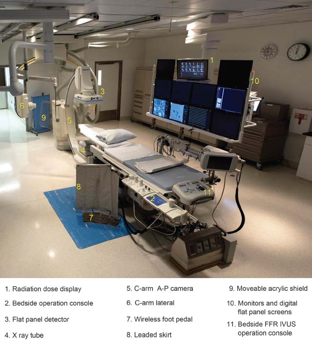
FIGURE 44.1 Cardiac catheterization laboratory with biplane imaging capabilities. 1, Radiation dose display; 2, Bedside operation console; 3, Flat panel detector; 4, X-ray tube; 5, C-arm A-P camera; 6, C-arm lateral; 7, Wireless foot pedal; 8, Leaded skirt; 9, Moveable acrylic shield; 10, Monitors and digital flat panel screens; 11, Bedside FFR IVUS operation console.
X-Ray Tube
The x-ray tube consists of a rotating anode and generally a multifilament cathode situated inside an evacuated glass tube. The x-ray tube is immersed in oil for efficient cooling and placed inside a lead housing to limit unwanted radiation. The filament consists of a thin tungsten wire through which a high electric current is passed heating the wire white hot. This thermal energy is sufficient to allow some electrons to overcome the electron-binding energy and provide essentially unbound electrons around the filament. This is often referred to as an electron cloud. When the system is energized, these electrons are accelerated toward and collide with the positively charged tungsten target (anode). The larger the filament, the more electrons that can be generated at one time; however, the focal spot on the anode also increases in size resulting in increased geometric blurring that degrades resolution.
All operators of radiographic equipment should understand three commonly used units displayed on all modern fluoroscopes. The milliamperes (mA) is the first unit, and it is related to the number of electrons traveling across the anode–cathode gap per second. The base unit ampere is defined as the number of coulombs per second (charge per unit time), hence a current. This is exactly what occurs when the electrons flow across the anode–cathode gap. The coulomb (C) is a unit of charge; the charge of one electron is 1.60 × 10⁻¹⁹ C. The next unit is related to the first but fundamentally different; it is the milliampere × seconds (mAs). The mAs is the total number of electrons traveling across the anode–cathode gap for a given exposure. The mAs is obtained by multiplying the first unit, mA, by time in seconds (s), which yields a measure of total charge (coulombs/second × seconds = coulombs). The third unit, peak kilovoltage (kVp), is equal to the applied voltage across the anode–cathode gap, which also represents the highest potential photon energy in the x-ray beam. The base units of voltage are joules/coulomb (energy per unit charge). The electrons, being charged particles, are accelerated across the gap due to the applied voltage, and therefore they gain kinetic energy. This kinetic energy is converted to electromagnetic radiation when the electrons interact with the tungsten target, primarily producing heat in the form of infrared photons, while a small fraction are converted to x-ray photons. The x-ray photons are generated isotropically, that is, with the same intensity in all directions. However, only those x-rays traveling through a small solid angle toward the x-ray tube window are used for imaging purposes. Lead shielding surrounding the x-ray tube is used to attenuate most of the unwanted x-rays; however, leakage radiation (radiation penetrating the x-ray tube housing) can be as high as 880 μGy/h (100 mR/h) at a distance of 1 m, limited by state and federal regulations, though it is commonly well below this value. In terms of affecting the output of the x-ray tube, increases in mA (or mAs) increase the radiation output linearly. As a rule of thumb, increasing kVp from kVp1 to kVp2 increases the output of the system by the ratio of (kVp2/kVp1)2. Therefore, in general, increases in kVp result in a larger increase of x-ray tube output as compared to a comparable increase in mA (or mAs). Increasing kVp not only increases the radiation output of the x-ray tube but also increases the effective energy of the x-ray beam resulting in a more penetrating beam.
Image Receptor
There are two types of image receptors used in fluoroscopes: image intensifiers and digital flat panel detectors. Most state of the art fluoroscopic systems dedicated for cardiac catheterization employ digital flat panel detectors, which are required for 3-D volume imaging. Regardless of the type, the image receptor captures and converts x-rays transmitted through the patient to a signal (analog or digital) for display. It is also involved in regulating the output of the x-ray tube via a feedback loop that governs the generator and x-ray tube output.
Generator
The generator is the component responsible for supplying the electrical power to the x-ray tube. Through step-up or step-down transformers, it supplies a low current and high voltage to the anode and a high current and low voltage to the cathode, respectively. There are a variety of types of generators; however, most modern fluoroscopes use a high-frequency generator, which supplies a very stable voltage and current to the x-ray tube.
Operating Console
The operating console, in conjunction with the system software, is the interface with the fluoroscope. Commonly, there is a primary operating console that provides display and control of many of the fluoroscopic operating parameters and communicates with both the Hospital Information System (HIS) and the Picture Archiving and Communication System (PACS). There is also typically a bedside console that controls most of the fluoroscopy and acquisition functions, mechanical operations such as rotation and angulation of the C-arm, and image display properties.
RADIATION DOSE ESTIMATION AND DISPLAYS
Understanding radiation dose can be complicated. There are an inordinate number of radiation quantities, some of which are rather abstruse. Compounding this problem, there is a traditional and a System International (SI) set of radiation units. It is important to understand the fundamental radiation quantities and their units, some of which are displayed on modern fluoroscopes (Table 44.1).
TABLE
44.1 Radiation Dose Quantities

aQuantities commonly found on modern fluoroscopes
Radiation quantities commonly displayed on modern fluoroscopes are the air kerma rate at the reference plane  a,r, air kerma at the reference plane Ka,r, and air kerma area product PKA commonly referred to as dose-area product (DAP) (Figs. 44.2 and 44.3). The usual dose units for
  a,r are mGy/min, for Ka,r are mGy, and for PKA are mGy cm2 or μGy m2. It is important to appreciate what these quantities are and what they are not. First, none of these quantities directly represents the patient’s peak skin dose Dskin,max, which is a quantity that is often sought to predict potential cutaneous injury.
  a,r and Ka,r are defined in air at a reference plane, often referred to as the interventional reference plane (IRP). The International Electrotechnical Commission (IEC) standards establish the IRP at a fixed distance 15 cm below the isocenter of the C-arm irrespective of the table height (Fig. 44.4). The assumption is that the center of the patient is at isocenter of the C-arm and that the patient is approximately 30 cm thick. Therefore, the IRP and skin entrance are both assumed to be 15 cm below isocenter. Ka,r and PKA are cumulative quantities for the entire procedure. They include radiations delivered at all projections and locations along the cranial–caudal direction (z). There are multiple reasons why Ka,r is not a surrogate for Dskin,max:
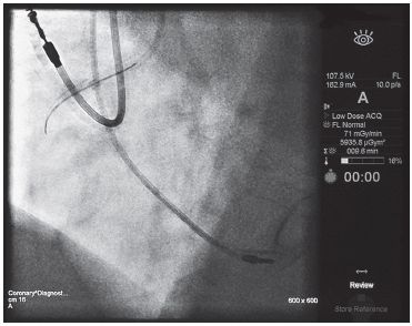
FIGURE 44.2 The displayed air kerma rate at the reference plane in this coronary cineangiogram is 71 mGy/min and the air kerma area product, commonly referred to as DAP, is 5,935.8 μGym2.
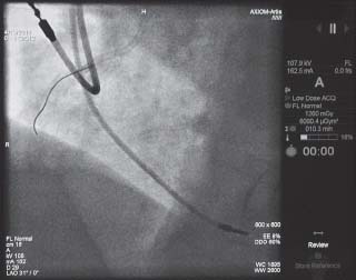
FIGURE 44.3 The air kerma at the reference plane, commonly referred to cumulative dose, is 1,260 mGy and the air kerma area product, commonly referred to as DAP, is 6,090.4 μGym2.
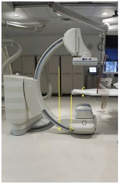
FIGURE 44.4 The x-ray focal spot is denoted on the fluoroscope by a small red dot on the x-ray tube housing (black circle). The source to image distance is the distance between the x-ray focal spot and the image receptor (A). The source to skin entrance distance is the distance between the x-ray focal spot and the table (B). The IRP is located at 15 cm below the isocenter of the C-arm, (C).
1. The IRP used for the Ka,r and the plane of the skin entrance are rarely the same; they may differ, depending on the projection (AP vs. vlateral), the size of the patient, or the height of the table.
2. Ka,r includes all radiations emitted from the x-ray tube. Many procedures use multiple projections at various locations along the z-axis that spreads the radiation delivered to the patient over a greater anatomical region generally reducing Dskin,max (as long as the fields of view do not overlap).
3. Ka,r by definition assumes that the medium of interaction is air. However, the absorption characteristics of skin and thereby Dskin,max are different from air. Furthermore, Dskin,max includes backscattered radiation as well, while air kerma does not.
The intensity of radiation follows the inverse square law that is the amount of radiation received drops by the inverse square of the distance (d) from the source, 1/d2. This is true for both patients and operators. Below are two clinical scenarios that exemplify limitations in air kerma as a proxy for peak skin dose.
Scenario 1
A small patient (~20 cm thick in the AP dimension) undergoes a cardiac catheterization. The physician performing the procedure is tall and performs the procedure with a source to image distance of 120 cm, source to skin entrance distance of 100 cm, and the image receptor lowered to the patient’s chest. For calculation purposes, let us assume there were two discrete nonoverlapping fields that equally split a total Ka,r of 4 Gy, the IRP is 60 cm from the x-ray tube focal spot, and that all imaging was performed in the straight AP projection (Fig. 44.5).
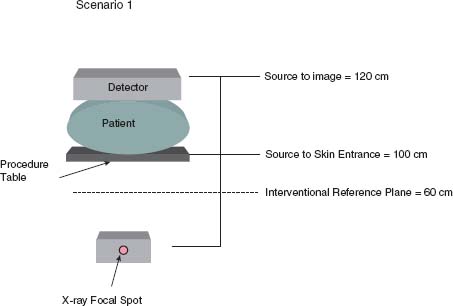
FIGURE 44.5 In Scenario 1, a relatively small patient 20 cm thick in the AP dimension undergoes catheterization. The source to image distance is 120 cm and the source to skin entrance distance is 100 cm. The IRP is approximately 60 cm above the x-ray tube. Because the radiation intensity drops as the inverse square of the distance from the x-ray source, the air kerma at the reference plane in this example grossly overestimates the air kerma at skin entrance.
Taking into account the inverse square law, the incident air kerma at skin entrance location Ka,i is less than the displayed Ka,r by (60/100)2 × Ka,r = 0.36 × Ka,r. Furthermore, because the radiation was split between two discrete fields, each field actually receives only half of the total air kerma, 0.36 × 0.5 × Ka,r = 0.18 × Ka,r. In other words, the actual air kerma at the skin entrance is 18% of the displayed air kerma at the reference plane, the Ka,r is a gross overestimation in this scenario. To obtain an estimated Dskin,max, the backscatter factor and tissue to air differences must be accounted for which will increase the Ka,i by about 30% to 50% depending on the x-ray beam characteristics, bringing the displayed value slightly closer to Dskin,max, but still off by approximately 75%.
Scenario 2
A morbidly obese patient (~50 cm thick in lateral dimension) undergoes a cardiac catheterization. Standard size collimator covers are removed and replaced with short collimator covers allowing for a source to skin entrance distance of 30 cm. The procedure requires only one unique lateral view (Fig. 44.6).
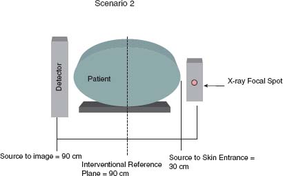
FIGURE 44.6 In Scenario 2, a relatively large patient 50 cm thick in the lateral dimension undergoes catheterization. The source to image distance is 90 cm and the source to skin entrance distance is 30 cm. The IRP is approximately 60 cm above the x-ray tube. Because the radiation intensity drops as the inverse square of the distance from the x-ray source, the air kerma at the reference plane in this example grossly underestimates the air kerma at skin entrance.


