FIGURE 17-1 Anchoring balloon technique for proximal RCA CTO. A: Proximal tapered occlusion, JR4 6F guiding catheter (right radial approach). B: Anchoring 1.5-mm monorail balloon in an infundibular branch after CTO wire crossing. C: A monorail balloon is crossing the occlusion (white arrows). D: Final result.
Specific Issues of Transradial PCI for CTO
The pitfalls of transradial PCI in the setting of CTO have been described as follows:
• Higher degree of technical difficulty compared with the transfemoral route.
• The size of the radial artery does not allow utilization of large-diameter guiding catheter to accommodate the equipment required and apply appropriate technical strategies.
• The small-diameter guiding catheters used via the transradial route do not provide adequate support.
• Difficulty in using a bilateral route.
Radial puncture undoubtedly poses more difficulties than does femoral puncture. However, the rate of success is closely related to operator experience.36 Although unpredictable, congenital anatomical variations (antebrachial loops, retrooesophageal right subclavian artery, etc.)37,38 can be crossed using appropriate techniques. Acquired difficulties39–41 such as stenosis or occlusion are less frequent compared with the femoral route. Antebrachial, brachial, and especially subclavian loops (less frequent on the left side) are associated with long-standing hypertension, older age, and obesity, all of which increase the risk of complications related to the transfemoral approach.42
The mean diameter of the radial artery has been assessed and reported in a few previous series. In a series involving 120 male and female patients published by our group, the diameter was 2.9 + 0.6 mm by ultrasound assessment. In a Korean series involving 1,191 cases, the mean angiographic diameter was 2.66 ± 0.44 mm (2.69 ± 0.40 mm in males and 2.43 ± 0.38 mm in females) (Dr. B. S. Yoo, personal communication, October 10, 2002). In a Japanese population of 250 male and female patients, the median diameter measured by ultrasound was 3.15 mm in males and 2.85 mm in females.43 In this Japanese series, the radial arteries accommodated a 6F introducer in 92% of male patients and 82% of female patients, a 7F introducer in 76% of male patients and 57% of female patients, and an 8F introducer in 45% of male patients and 25% of female patients. In our European series, 6F, 7F, and 8F introducers were used in 86.9%, 76.9%, and 64.7% of a mixed group of male and female patients, respectively.
Table 17-1 lists the compatibility between the equipment and the technical strategies applied in the treatment of CTO, the size of guiding catheter and introducers, and their compatibility with the transradial approach in a French population. The use of a 6F catheter with an introducer enables the implementation of strategies such as the anchoring balloon technique with a monorail balloon inserted simultaneously with another monorail balloon or a microcatheter (Finecross, Terumo, Terumo Corp., Tokyo, Japan) (Fig. 17-2). However, a 7F catheter is required for the penetration of the proximal cap with a wire and a microcatheter under IVUS (intravascular ultrasound) guidance (Fig. 17-3).
There is a difference in the diameter between an introducer and a guiding catheter of similar nominal size (around 2F). Measurements assessing the compatibility between an introducer and a radial artery only involve the segment of the introducer inserted in the most distal and the narrowest segment of the radial artery. Attempts at decreasing the sheath diameter by reducing the thickness of the wall are ongoing. Sheathless guiding catheters (Asahi) (Fig. 17-4)44 may allow the use of larger-diameter catheters via the radial approach. Their efficiency is largely dependent on their hydrophilic nature enabling the crossing of, for instance, the proximal segment of brachio-radial arteries (high take-off radial artery),45 which can be very narrow, in the absence of any connection with the brachial artery at the elbow level.
TABLE 17-1 Compatibility of Materials and Techniques with 5F to 8F Guiding Catheters and Sheath Size in a French Population
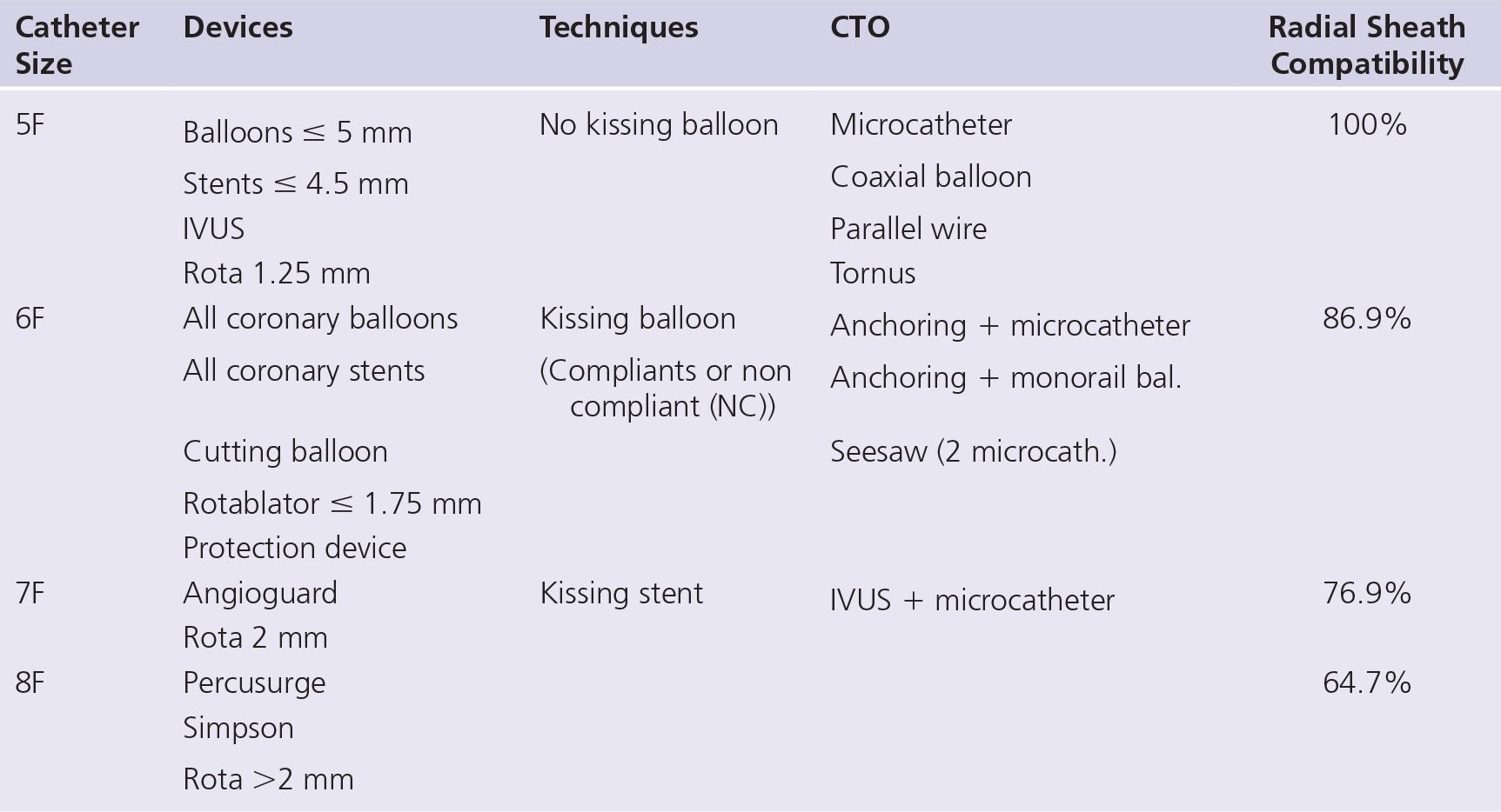
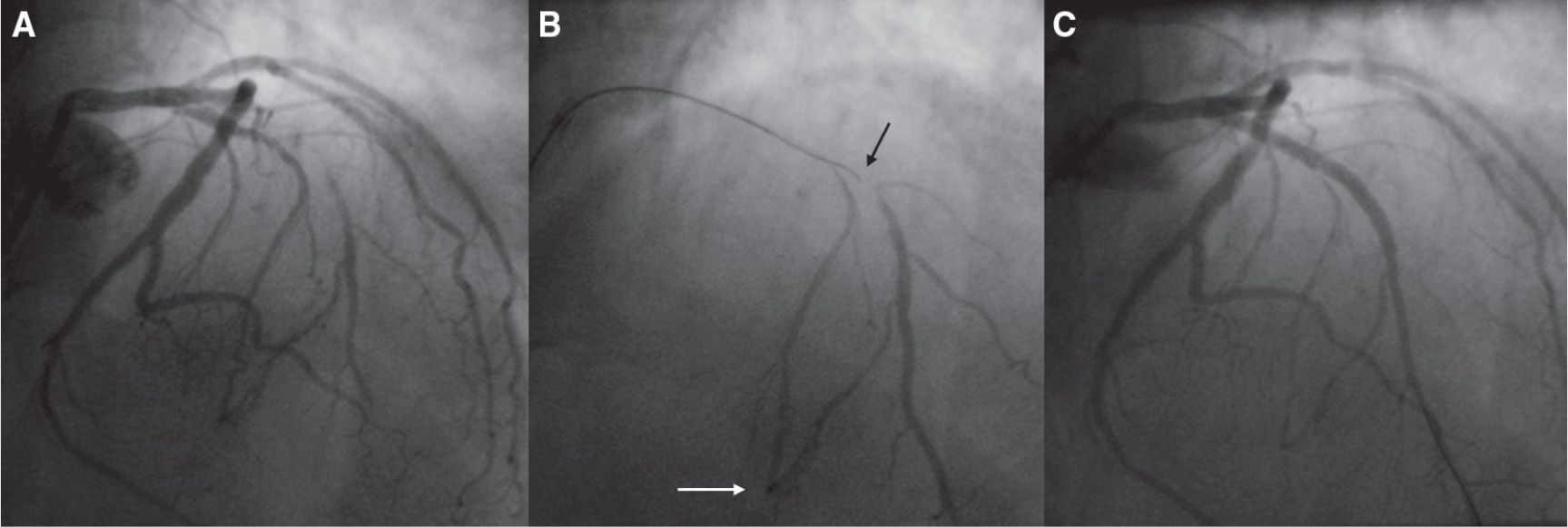
FIGURE 17-2 “Micro guidance” for a short mid-LAD CTO with ambiguous take-off. A: Extra back-up (EBU) 3.5 guiding-catheter injection (right radial approach). B: Finecross microcatheter injection deeply in the second septal branch (white arrow) while a Fielder XT wire, Asahi-Intecc, Aichi, Japan is crossing the occlusion (black arrow). C: Final result.
Even in settings other than CTO treatment, radial operators have long been developing technical strategies to make up for the weakness of guiding catheter passive support in the coronary ostium (sensitivity to respiratory movements, use of guiding catheter shapes adapted to transfemoral procedures, etc.). Certain catheter shapes provide better backup support at the level of the coronary ostium in the setting of complex CTO angioplasty. Left Amplatz shapes are very useful for lesions located in the circumflex artery and sometimes in the left anterior descending (LAD) artery (AL2 or AL3 left Amplatz) or the right coronary artery (RCA) (AL1 or AL2) (Fig. 17-5). However, active support techniques using 6F guiding catheter are widely applied by experienced transradial operators (Fig. 17-6). Certain guiding catheter shapes facilitate deep-seating intubation (three-dimensional right catheter) (Fig. 17-7). The mother-and-child technique (child-in-mother technique) was first described by Saito as follows: a 5F catheter (Heartrail, Terumo), longer than the guiding catheter by 15 cm, is inserted into a nonspecific 6F guiding catheter and advanced over a wire inside the target artery. This enhances guiding catheter support in direct proportion to the length of the intubated segment and may provide the same backup as would an 8F guiding catheter positioned at the ostium (Figs. 17-8 and 17-9).46–48
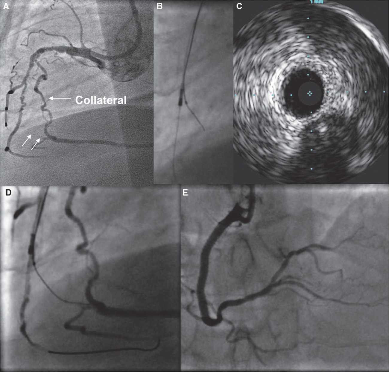
FIGURE 17-3 IVUS-guided penetration for a very old CTO (20 years) initially on the RCA first segment. Reperfusing channels on first and second segments (sinuosities). The patient is symptomatic despite a big homolateral collateral channel. The occlusion site is not clearly visible but the end is (white arrows). A: The guiding catheter is an AL2 7F from right radial. B, C: After proximal and mid-RCA balloon angioplasty, an IVUS catheter is pushed on a wire in a right inferior ventricular branch, and a Finecross microcatheter is pushed slightly proximal to the occlusion cap clearly visible on IVUS. D: An XT wire is pushed in the occlusion to the distal bed. E: Final result.
The Guideliner guiding catheter extension (Vascular Solutions, Minneapolis, USA) was designed according to the same principle in order to provide enhanced support for stent or balloon delivery.49,50
Other guiding catheter stabilization techniques are available, such as the anchoring balloon strategy.35,51–55 This technique may be implemented in a side branch proximal to the occlusion or an arterial segment distal to the occlusion by retrograde insertion of a balloon, in the anterograde guiding catheter following retrograde crossing of the occluded segment, or in the guiding catheter before wire externalization (Fig. 17-10). The use of a Proxis catheter designed for proximal thromboaspiration may help to stabilize the guiding catheter and to allow stent delivery.56 A conventional thromboaspiration catheter may serve the same purpose.57
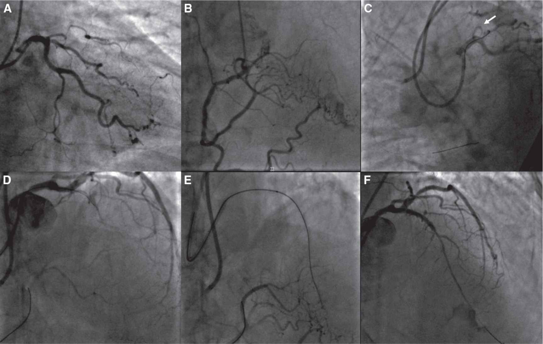
FIGURE 17-4 Bilateral radial approach for a short proximal LAD CTO. A: RAO view from coronary angiography. B: Collateral filling from RCA with some good channels. C: Bilateral injection in the RCA with a 6F JR4 guiding catheter (and a BMW wire to stabilize it), and an SPB4 (EBU-like) sheathless (from right radial) in the LCA (a potential take-off is shown by the white arrow). D: A Fielder XT wire supported by a Finecross microcatheter is reaching the distal bed. E: XT wire deeply in the LAD (controlateral injection). F: Final result.
Although considered an acrobatic maneuver, simultaneous injection in both coronary arteries via the two radial arteries is frequently performed. However, certain catheterization laboratory setups were designed to allow operators to carry out bilateral transradial procedures in comfortable conditions both for the operator and for the patient (arm support, inflatable or shapeable cushion) (Fig. 17-11), as in the setting of transfemoral procedures.
Transradial PCI Treatment of CTO: Experience and Results
The use of the transradial route in the percutaneous treatment of CTO has been reported in a few case reports and short series. In 2006, Kim et al.58 achieved a 65.5% success rate in 85 patients. In 2010, Yang et al. published a series of 419 CTO procedures, of which 400 were carried out via the radial approach, with a 69.25% success rate.59 In 2011, Liu et al. reported a consecutive series of 120 patients treated through the transradial approach, with an 80% success rate, demonstrating the feasibility of this vascular route.60 In 2011, Wu et al.62 described bilateral transradial techniques whereby 7F catheters of 85 cm length were positioned 10–15 cm above the radial styloid; 71.8% of CTOs were treated via the retrograde route and the operators achieved a remarkable global success rate of 87.7%.61 In 2011, Rinfret et al.62 published a single-operator series of 42 patients treated via the retrograde approach, with an 88% success rate.
All the above-mentioned series demonstrated in a more or less convincing manner the feasibility of transradial angioplasty, including the bilateral radial approach and retrograde routes, in the treatment of CTOs.
To date, there are no randomized studies comparing the radial and femoral routes in the PCI of CTOs. However, a comparison between the two strategies was carried out in two single-center registries.
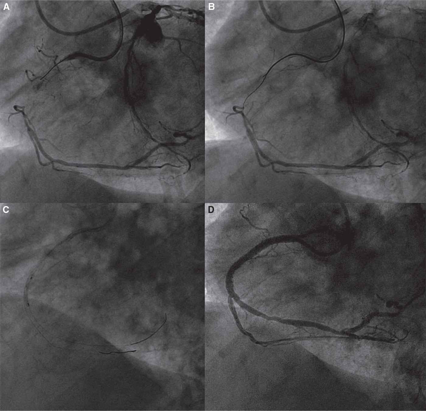
FIGURE 17-5 Bilateral radial approach for a long tapered proximal RCA CTO. A: Double injection: EBU 4F 6F guiding catheter from left radial artery for LCA, AL2 6F guiding catheter from the right radial artery for RCA. B: CTO crossing with a Fielder XT wire without support. C: Balloon angioplasty. D: Final result.
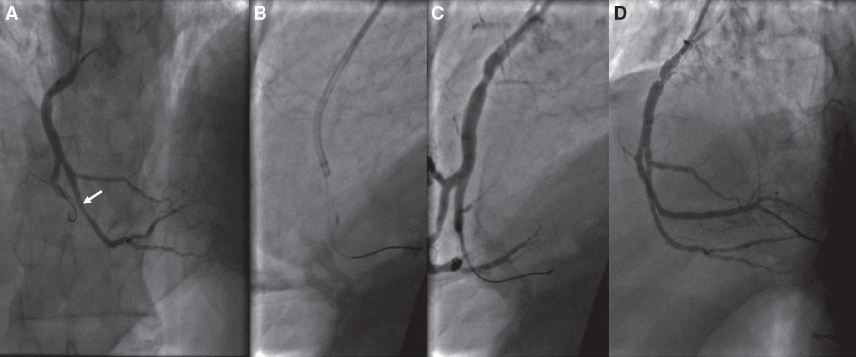
FIGURE 17-6 Catheter deep seating in an occluded RCA. A:
Stay updated, free articles. Join our Telegram channel

Full access? Get Clinical Tree


