Prosthetic Valves and Rings
Prosthetic valves may be made from metal and other material or may be biologic grafts (i.e., heterografts, homografts, or autografts). Mechanical grafts last longer than bioprostheses but require long-term anticoagulation. The potential advantage of the bioprostheses is that anticoagulation is required only early after placement unless indicated for other reasons, such as the presence of atrial fibrillation. Porcine heterografts are the most commonly used ones; they cannot be implanted in children, however, because of the relatively rapid calcification that occurs. Homografts (i.e., human valves) and autografts (i.e., grafts from the same individual—as in the placement of the pulmonary valve in the aortic position) may be less prone to calcification. The Ross procedure is a recently developed surgical approach in which the patient’s pulmonary valve is placed in the aortic position and a homograft is placed in the pulmonary position. The lower pressure gradient across the homograft in the pulmonary position may make it less prone to calcification. An important role of transesophageal echocardiography is to measure the size of the annulus to be certain that appropriately sized homografts are available and, in the case of the Ross procedure, to be certain that the pulmonary valve is of the right size for placement in the aortic position.
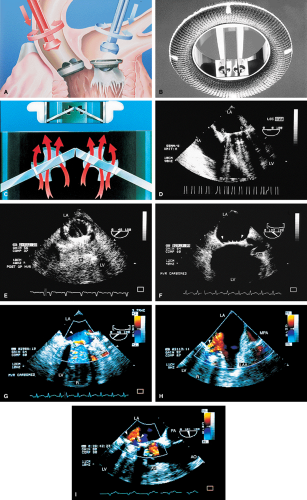
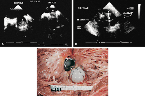
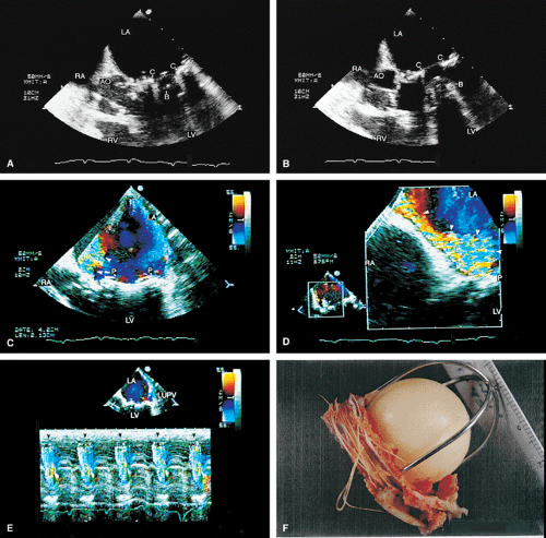
The most commonly used mechanical valve is the St. Jude valve. Newer valves such as the Carbomedics (Sulzer Carbomedics Inc., Austin, TX) and Medtronic-Hall (Meditronics, Inc., Minneapolis, MN) valves are preferred by some surgeons, and their use is increasing. The echocardiographer must also be familiar with other valves, such as the Bjork-Shiley and Starr-Edwards valves, because large numbers of these implants are still functioning.
Problems that can occur with all valves include paravalvular leaks, infection, and thrombus. Bioprosthetic valves may also calcify and degenerate.
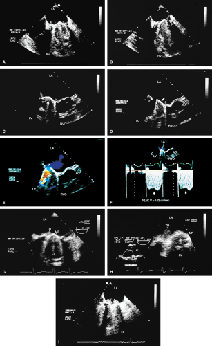
Because all mechanical and bioprosthetic valves are inherently a little stenotic, a region of flow acceleration can often be seen proximal to the valve during the flow across the valve. Because of the presence of localized areas of high-velocity flow, the Doppler study may overestimate the gradient across the prosthetic valve. The assessment of the prosthetic valve stenosis must therefore be approached with great caution, and published tables giving normal ranges for various prosthetic valves are not very helpful. The problem is further complicated by prosthesis–patient mismatch seen in some patients. Therefore, high-pressure gradients noted across prosthetic valves, especially metallic ones, do not necessarily imply obstruction. Because of this, measurement of prosthetic orifice areas using the Doppler continuity equation or pressure half-time method may not be accurate. A baseline study performed at the time of surgery can be helpful so that changes in pressure gradients can be followed up over time. It is important to investigate the motion of the occluder or leaflets when assessing stenosis. Immediately after the termination of cardiopulmonary bypass, the flow may be inadequate to open one of the leaflets of the mechanical prosthetic valve. This is a normal finding that resolves over time as cardiac output increases. For valves in the mitral position, a flat EF slope in association with a high velocity on conventional Doppler study suggests obstruction.
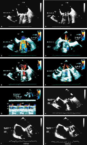
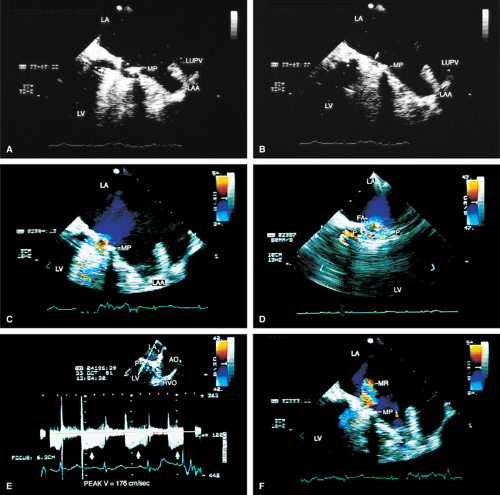
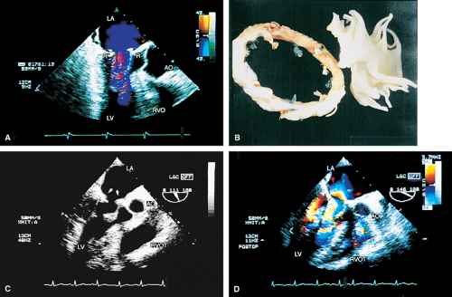
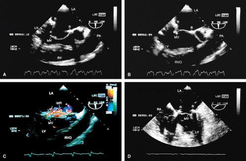
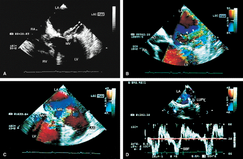
Valve prostheses may normally have a small amount of regurgitation. In the case of the St. Jude and CarboMedics valves, up to three small regurgitant jets are seen. These correspond to the two leaflets and to a central jet. Compared with pathologic regurgitant jets, these normal jets tend to be more laminar and narrow. In mitral prostheses the jets may, however, extend well into the left atrium. In assessing the severity of the prosthetic mitral regurgitation, it is important to investigate the pulmonary veins near their entry into the left atrium with the conventional Doppler to search for systolic backflow, which is a reliable marker for severe regurgitation. The size of the proximal flow acceleration should also be assessed. Finally, the area of the jet is important (<4 cm2, mild regurgitation; 4 to 8 cm2, moderate regurgitation; >8 cm2, severe regurgitation), although jet area may be misleading if an eccentric jet is present. Multiple planes
should be interrogated to find the plane in which the regurgitant jet has the largest area. The Nyquist limit should be kept between 40 and 50 cm/sec. Changes in the Nyquist limit, and consequently the wall filter, will affect the jet area. The spontaneous contrast in the left atrium suggests that any mitral regurgitation is not severe. In the case of aortic prostheses, the aortic regurgitant jet may be seen best by the transthoracic approach because there is acoustic shadowing of the jet on the transesophageal examination, caused by the metallic components and posterior calcification. For prostheses in the aortic position, the severity of the regurgitation is assessed by determining the ratio of jet width at its origin to left ventricular outflow tract diameter, also measured at the origin of the jet (<38%, mild; 39% to 75%, moderate; >75%, severe).
should be interrogated to find the plane in which the regurgitant jet has the largest area. The Nyquist limit should be kept between 40 and 50 cm/sec. Changes in the Nyquist limit, and consequently the wall filter, will affect the jet area. The spontaneous contrast in the left atrium suggests that any mitral regurgitation is not severe. In the case of aortic prostheses, the aortic regurgitant jet may be seen best by the transthoracic approach because there is acoustic shadowing of the jet on the transesophageal examination, caused by the metallic components and posterior calcification. For prostheses in the aortic position, the severity of the regurgitation is assessed by determining the ratio of jet width at its origin to left ventricular outflow tract diameter, also measured at the origin of the jet (<38%, mild; 39% to 75%, moderate; >75%, severe).
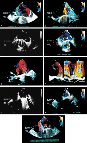
Paravalvular leaks may be important causes of regurgitation. These leaks may be caused by valve suture dehiscence and can be seen to originate beyond the extent of the prosthetic elements. The location of proximal flow acceleration outside the confines of the prosthesis may also help determine if the leak is paravalvular.
Thrombi can lead to emboli or to obstruction or may interfere with the function of a valve and cause significant regurgitation. Thrombi may be present in the left atrium or left atrial appendage and may well be seen on the transesophageal study. Because the left atrial appendage may be partially or completely removed at the time of surgery, inability to image it should not be taken as evidence that there is a clot obscuring the appendage. Left ventricular function is better preserved if the papillary muscles are not completely removed; remnants of the papillary muscle and chordae left in place by the surgeon may be mistaken for a mobile clot. For this reason, a baseline transesophageal study is of great use for comparison.
Transesophageal and transthoracic examinations are complementary in patients with a mitral valve replacement. Transesophageal study is far more effective than is transthoracic examination in assessing the left atrium for the presence and severity of mitral regurgitation in patients with valves in the mitral position. On transthoracic study, acoustic shadowing of the left atrium by the valve is observed. Conversely, substantial acoustic shadowing and reverberation that degrade the transesophageal image of the left ventricle are present on transesophageal study but not on transthoracic examination.
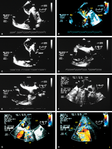
Certain structures are well examined by transesophageal echocardiography. The short-axis view of a prosthetic valve permits a complete view of the valve suture line. Stents are well seen, and, in the case of mitral prostheses, may physically narrow the left ventricular outflow tract or may impinge on the left ventricular free wall or ventricular septum, producing arrhythmias or conduction system abnormalities. Bioprosthetic mitral cusp rupture resulting from degeneration or infection may be manifested as linear echoes protruding into the left atrium, with or without fluttering. Left atrial perforation or dissection may be seen. Abscesses may be visualized. They may be large and filled with pus. The presence of flow signals in the abscess cavity demonstrates that there is communication with an adjoining vessel or cavity. Abscesses may form fistulas to other structures. Following aortic valve replacement, systolic anterior motion of the mitral valve may be unmasked, and significant left ventricular outflow tract obstruction may develop in the presence of coexisting hypertrophic cardiomyopathy. Rarely, a left ventricular outflow tract gradient may be caused by an abscess narrowing the outflow tract. Pannus may cause obstruction and may be difficult to distinguish from clot. If the obstructing echo density is mobile and less dense thrombus is more likely. Bioprosthetic valves may suffer cusp degeneration or calcification, which may produce obstruction. Linear echoes protruding into the left ventricular outflow tract are characteristic of prolapse caused by bioprosthetic aortic valve degeneration. Similar echoes may also be caused by infection.
Transesophageal echocardiography is also useful in the assessment of mitral annuloplasty rings, which are placed to reduce the severity of mitral regurgitation. Residual mitral regurgitation, as well as ring thrombus, obstruction, and dehiscence, are well demonstrated. Systolic anterior motion of the anterior mitral leaflet with left ventricular outflow tract obstruction may also occur after ring placement and can be diagnosed by echocardiography. In patients undergoing aortic valvuloplasty, the site of aortic valve repair and the severity of residual aortic regurgitation are also well assessed by transesophageal echocardiography.
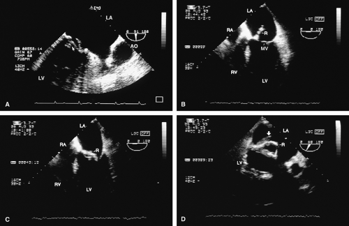 FIGURE 5.17. Mitral annuloplasty ring: thrombus/dehiscence. A. A thrombus (arrow) involving the ventricular aspect of a Duran ring. There is severe mitral valve (MV) prolapse. B–D.
Get Clinical Tree app for offline access
Stay updated, free articles. Join our Telegram channel
Full access? Get Clinical Tree


|
