Programmability is defined as the ability to make noninvasive, stable but reversible changes in device function. The first truly programmable pacemakers were introduced in 1972 in which a magnetic code was introduced from an external programmer to manipulate four levels of output and six variations of pacing rate. Radiofrequency signals are now exclusively used to communicate between the device and the programmer. The number of programmable features and the variability of each feature have dramatically expanded and offer the ability to uniquely alter device function to meet the specific needs of the patient.
Programmers
Although all programmers allow completion of similar tasks, there is considerable difference among manufacturers in implementation with regard to screen layout, use of touch screen and stylus, number of automatic “measurement” functions, position and operation of emergency programming options, and so on.1 Thus, programmer-specific familiarity is required for device programming.
Pacemaker Programming
All contemporary devices are programmable. The North American Society of Pacing and Electrophysiology/British Pacing and Electrophysiology Group (NASPE/BPG) code designates the degree of programmability.2 The first letter indicates the chamber(s) paced, the second the chamber(s) sensed, and the third the response. Thus, VVI indicates the ventricle is paced and sensed, and an intrinsic event inhibits output. A fourth letter code describes rate modulation. An “R” in the fourth position indicates that the pacemaker has a sensor to control the rate independent of intrinsic electrical activity of the heart, typically used to increase the heart rate during exertion.
It is important to have a systematic approach to programming. Although the manufacturer-specific approaches differ, a programming sequence should include specific assessments, data collection, and interpretation and optimization if needed.
Most programmable parameters have been discussed in Chapter 7: Timing Cycles, and it is not the purpose of this chapter to discuss each programmable value individually. Nor is there an attempt to cover nuances of specific manufacturers or models. As always, it is important to consult the technical manual and/or the manufacturer’s technical services helpdesk for further information about a specific pulse generator or specific feature. Table 8.1 attempts to include most available programmable features and a general range of the programmable values for each parameter.
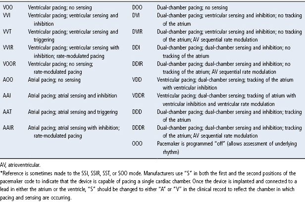
Table 8.1 Pacing modes.*
Source: Hayes DL, Lloyd MA, Friedman PA. Cardiac Pacing and Defibrillation: A Clinical Approach. Armonk, NY: Futura Publishing Co., Inc., 2000: 247–323, by permission of Mayo Foundation for Medical Education and Research.
The chapter is structured by major programmable parameters and programming considerations for each. Programmer “screen shots” will be used to demonstrate the type of information available and steps to assessment and optimization when needed.
Interrogation
Interrogation is performed by placing the programming head over or near the pulse generator to establish a communication; in devices equipped with a radiofrequency link the programmer can be within 6–10 feet of the patient, with minor variation among manufacturers. Most contemporary pulse generators are automatically recognized by the programmer and a full interrogation or a display of programmed parameters will be generated.
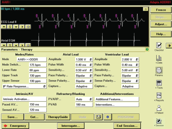
The initial screen usually displays key programmed parameters, alerts that have occurred since the last interrogation, and options to access other data (Fig. 8.1).
Fig. 8.1 Programmer screen demonstrating primary programmable parameters and other drop-down menus to access additional parameters. There are also other icons to the right to connect to stored data, tests that can be accomplished via the programmer, reports and patient information.
Emergency Programming
In order to avoid asystole during the course of programming in a pacemaker-dependent patient, every programmer is equipped with an emergency or “stat set” button that restores nominal pacing parameters when activated. However, there may be a delay between activation of the stat set parameters and actual restoration of nominal pacing parameters. It is important that the caregiver using the programmer be familiar with the specific programmer steps necessary to activate stat set or emergency backup parameters.1
Programmed Parameters
One or more screens specifically display the programmed parameters. Drop-down menus or other paths display less commonly used programmable parameters or “advanced” programmable parameters.
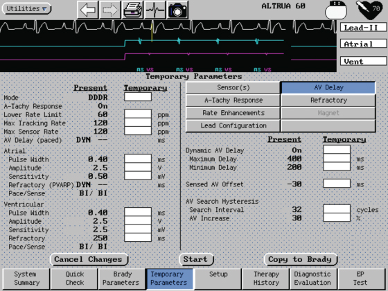
Parameters may be reprogrammed either directly from the “parameter” screen or from “temporary programming” screens that permit routine programming sequences or troubleshooting without changing permanently programmed values (Fig. 8.2).
Fig. 8.2 Programmer screen demonstrating temporary programmability. The permanent settings at “present” are listed next to the “temporary” column. Temporary programming allows testing and specific programming sequences to be accomplished without having to alter the prior settings.
Measured Data
Measured data are used to modify or verify the appropriateness of programmed parameters and are therefore briefly discussed in this chapter.
- Impedance: Impedance values for atrial, right ventricular (RV), and/or left ventricular (LV) leads should be measured to assess lead function. Some pulse generators will also display prior value(s) or a “trend” of impedance measurements, which is diagnostically helpful (Fig. 8.3).
- P and/or R wave amplitudes: The size, in mV, of intrinsic activity should be measured and compared with prior values when available (Fig. 8.4).
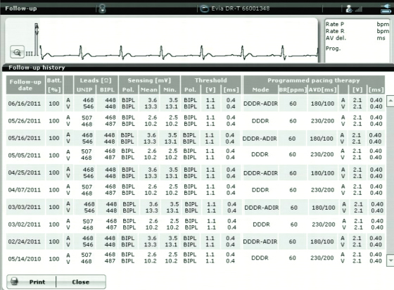
- Capture threshold(s): There are multiple ways the capture threshold can be determined. An autothreshold is usually available and can be configured to the preferences of a specific caregiver or institution. We generally perform capture thresholds at a fixed pulse width and decrement the voltage amplitude. (In some devices this may not be an option.) Some manufacturers require that a touch-sensitive area on the programming screen be held down during autothreshold measurement (during which pacing outputs are progressively decremented), so that upon loss of capture the operator simply removes pressure to restore pacing. Others only require that the autothreshold be initiated and the threshold search ends automatically upon detection of loss of capture (Fig. 8.5). In some pacemakers a screen may also be available that will display prior values for capture thresholds and other previously measured data (Fig. 8.6). (Chapter 1 reviews the concepts of pacing capture and sensing.)
Fig. 8.3 Follow-up screen giving an “overall” view of device status. Basic programmed values are shown in the left column. Battery status and percent pacing are also shown. Measured impedance values are provided, in this example atrial impedance = 448 Ω; ventricular impedance = 429 Ω. In addition, the measured intrinsic P and R waves are shown.
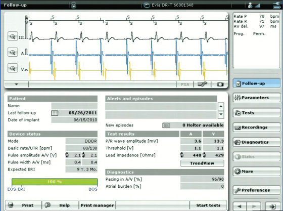
Fig. 8.4 An intrinsic amplitude test has been performed which measured a 2.8-mV unipolar P wave and a 3.3-mV bipolar R wave.
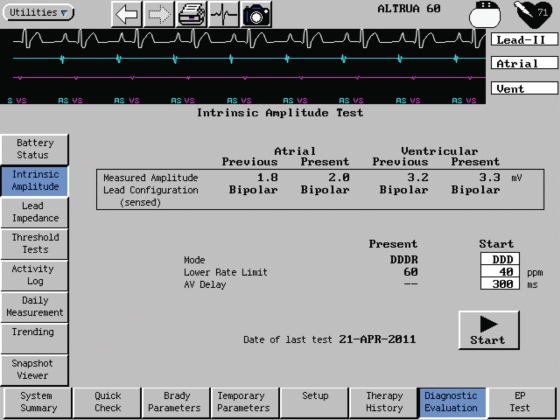
Fig. 8.5 Programmer screen from which threshold testing can be accomplished. In this example ventricular pacing threshold is being performed by decrementing the voltage amplitude at a fixed pulse width of 0.4 ms. The voltage threshold was 0.6 V in a bipolar configuration. The pacemaker is “auto” programmed to 1.1 V and 0.4 ms pulse width. The unipolar pacing threshold could not be determined because of an inadequate evoked potential signal.
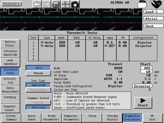
Fig. 8.6 Programmer screen demonstrating stored follow-up data. Information is available from multiple programming episodes and includes battery status, lead impedances, intrinsic P- and R-wave amplitude, atrial and ventricular pacing thresholds and programmed values.
Specific Programmable Parameters to Consider in All Patients
The degree of programmability varies significantly among pulse generators. Pacing mode options are listed in Table 8.1 and commonly used programmable parameters along with their definitions and typical values are listed in Table 8.2. The chapter is written with regard to current generation pulse generators, recognizing that the degree of programmability and the sophistication of programmable parameters may be significantly lower in earlier generation devices that remain in service. Although an attempt is made to discuss programming generically, this is not always possible. Specific programmable parameters may be protected by trademark and available from only one manufacturer. Therefore, it is necessary at times to refer to specific manufacturers and algorithms.
Table 8.2 Common programmable options for pacemakers.
| Parameter | Description | Potential programmable values |
| Atrial refractory period | An interval of the atrial channel timing cycle during which the atrial sensing amplifier is designed to be unresponsive to input signals. In some pacemakers, however, the sensing circuitry is alert for extraneous or noncardiac signals during a portion of the atrial refractory period. In single-chamber atrial pacing modes, the atrial refractory period occurs after a sensed or paced atrial event | 150–500 ms |
| Atrioventricular interval | Period between the initiation of the paced or sensed atrial event and the delivery of a consecutive ventricular output pulse | PAV (Paced AV) also “AV”: 25–350 ms SAV (Sensed AV) also “PV”: 25–325 ms |
| Circadian lower rate limit or sleep rate | Reduces the lower rate limit during sleeping or resting hours | Lower rates during sleep, programmable from as low as 30 ppm |
| Differential AVI | Feature that permits a longer AVI after a paced atrial event (PAV) than after a sensed AVI (SAV). In many pacemakers these are independently programmable (see immediately above). In some the differential is fixed; and in others, it is programmable as a single AV interval with an “offset” | Offset from 0 to 100 ms |
| Fallback | An upper rate response in which the ventricular paced rate decelerates to, and is maintained at, a programmable fallback rate that is lower than the original programmed MTR. Fallback mechanisms vary among pacemakers. Fallback may also be a programmable parameter related to the mode-switch algorithm indicating the paced rate that will be implemented when mode-switching criteria are met | May be programmable on or off; if on, the rate to which the fallback occurs may be fixed or programmable, i.e., 50–80 ppm |
| Lower rate limit | Preset or programmed rate at which a pacemaker emits an output pulse without intrinsic cardiac activity | 30–170 ppm (options faster than 150 ppm available in some pulse generators) |
| Magnet response | The response of a permanent pacemaker to magnet application is generally asynchronous pacing, and the behavior of an implantable cardioverter-defibrillator varies among manufacturers and possibly among models or generations of a specific manufacturer | Off, On, EGM storage, i.e., when magnet applied the pulse generator is triggered to store an EGM |
| Maximum sensor rate (MSR) | The fastest sensor-driven pacing rate that can be achieved in a rate-adaptive pacing system. In a single-chamber demand pacemaker with rate-adaptive capability (SSIR), the maximum sensor rate is the same as the programmed upper rate limit. In a dual-chamber rate-adaptive pacemaker (DDDR), the maximum sensor rate is not necessarily equal to the maximum tracking rate | 80–180 ppm |
| Maximum tracking rate (MTR) | The fastest atrial rate at which consecutively paced ventricular complexes maintain 1 : 1 synchrony with sensed atrial events. The maximum tracking rate is a function of dual-chamber pacing modes and can be defined as a preset or programmable value. The maximum tracking rate is limited to the total atrial refractory period (TARP) | 80–210 ppm |
| Mode (see Table 8.1) | Preset or programmed response from a pacemaker with or without intrinsic cardiac events | VOO, AOO, VVI, AAI, VDD, DVI, DDD, DDI, DOO, VVT, AAT (all could also have “R” (rate-adaptive) capability |
| Mode switch | Capability of a dual-chamber pacemaker to automatically switch from an atrial tracking (P synchronous) mode to a non-atrial-tracking mode when an atrial rhythm occurs that the pacemaker determines to be pathologic. When the atrial rhythm meets the criteria for a physiologic rhythm, the mode switches back to an atrial-tracking mode | On or off; if on, the detection rates are often programmable for rates 110–300 ppm; many variables other than the atrial tachycardia detection rate may be programmable depending on the specific mode-switching algorithm |
| PMT (Pacemaker Mediated Tachycardia) algorithms | A function of dual-chamber pacemakers that minimizes the initiation or continuation of a PMT. PMT algorithms vary in different pacemakers and usually are a programmable function. Examples of pacemaker-mediated tachycardia protection algorithms include lengthening of the programmed PVARP, an automatic extension of the atrial refractory period after a sensed premature ventricular contraction, and a dropped ventricular output pulse after a predetermined number of beats at a specified rate or upper rate limit | On or off; in others, can choose how long the MTR must persist before detection criteria are met |
| Polarity | Stimulating electrode typically is the cathode, which has negative polarity relative to the indifferent electrode (anode). If the anode is the “ring” of the pacing lead then a “bipolar” configuration is in use. If the anode is the pulse generator “can,” then a “unipolar” configuration is present | Options variable. Older pulse generators may simply be programmable to unipolar or bipolar and applies to any mode programmed and both pacing and sensing configuration In many devices the sensing and pacing polarity configurations are independently programmable and in many dual-chamber devices the atrial and ventricular channel are independently programmable |
| Postventricular atrial blanking period (PVAB) | A programmable feature in some dual-chamber pulse generators. During the period specified (in milliseconds), the atrial events are blanked from the atrial channel and therefore not considered when the atrial rate interval is calculated. The postventricular atrial blanking period is initiated with a ventricular paced or sensed event | 60–200 ms |
| Post-ventricular atrial refractory period (PVARP) | In dual-chamber pacemakers, that portion of the timing cycle during which the atrial channel is refractory after a paced or sensed ventricular event. The PVARP prohibits the atrial channel of the pacemaker from sensing the far-field ventricular depolarization or the afterpotential of the ventricular pacing impulse. If the PVARP is sufficiently long, it can prevent pacemaker-mediated tachycardia by prohibiting sensing of premature atrial beats or retrograde atrial depolarizations after ventricular ectopic or paced ventricular beats. However, extension of the PVARP limits the maximum tracking rate unless there is a rate-related shortening of the PVARP | 150–500 ms; in some devices, auto-PVARP adjusts with cycle length |
| Pulse amplitude | Magnitude of the voltage level reached during a pacemaker output pulse, usually expressed in volts | 0.25–8.4 V |
| Pulse width | Duration, in milliseconds, over which the voltage output is delivered | 0.05–1.5 ms |
| PVARP extension | Lengthening of the PVARP after a sensed premature ventricular contraction to prevent sensing of a retrograde P wave | On or off in some; others may program length of extension to as long as 500 ms |
| Rate hysteresis | Extension of the escape interval after a sensed intrinsic event | Off, 30–130 ppm. (Most commonly used is in SSI device with rates 30–60 ppm. However, in some, if N = the base rate, hysteresis is available at N − 5 or 10 ppm up to as the programmable base rate |
| Rate smoothing | Prevents atrial or ventricular paced rate from changing by more than a programmed percentage from one cardiac cycle to the next. This prevents large cycle-to-cycle intervals that can be seen at the upper rate limit or during rapid acceleration of atrial rate | On or off; when on options of percent smoothing, i.e., 3%, 6% and 24% change per cycle length allowed; may also have option of being on or off for rate increments or decrements, or both |
| Rate-adaptive AVI | Shortens the AVI as the heart rate increases | On or off only in some devices; in others, able to set the minimum AV delay to as short as 30 ms and in others there is a manufacturer-determined “scale,” e.g., low, medium, high that determines how aggressive the AVI shortening will be |
| Reaction time | A programmable parameter in some rate-adaptive pacemakers which determines how quickly the pacing rate will increase via sensor activation | 15–60 s |
| Recovery time | A programmable parameter in some rate-adaptive pacemakers that determines how quickly the sensor-driven pacing rate will decrease once the sensor is no longer activated | 2.5–16 min |
| Sensitivity | Ability to sense an intrinsic electrical signal, which depends on the amplitude, slew rate, and frequency of the signal | Atrial: 0.1–8 mV; ventricular: 0.5–14 mV |
| Sensor slope | A programmable value that determines the pacing increment over the base rate which will occur with different levels of sensor signal input | Usually a scale unique to the manufacturer, e.g., 1–10, 1–16 |
| Sensor threshold | A programmable value for rate-adaptive pacemakers which determines, in part, the level of activity necessary to activate the sensor. Programming the sensor threshold is not consistent across manufacturers. In some devices, the higher the sensor threshold is set, the greater the level of activity required to increase the pacing rate, and vice versa in others | Low, medium, high |
| Ventricular blanking period | A short preset or programmable interval in dual-chamber pacemakers during which the ventricular sensing amplifiers are disabled. Ventricular blanking is initiated by an atrial output pulse and is designed to eliminate ventricular sensing of the atrial stimulus (crosstalk) | Ventricular blanking: 20–50 ms |
| Ventricular refractory period | An interval of the timing cycle following a sensed or paced ventricular event. The ventricular channel is totally unresponsive to incoming signals or waveforms during the majority of the ventricular refractory period. However, in some pacemakers, the sensing circuitry is alert for extraneous signals during a portion of the ventricular refractory period. The ventricular refractory period also may be referred to as the ventricular refractory interval | 125–500 ms |
| Ventricular safety pacing (VSP) | Delivery of a ventricular output pulse after atrial pacing if a signal is sensed by the ventricular channel during the crosstalk sensing portion of the AVI | On or off in most pulse generators. When on the VSP interval is usually in the range of 90–120 ms. One manufacturer does not have VSP as a programmable option, but as a function of a noise detection algorithm |
Mode Programming
Pacing modes have been discussed in detail in Chapter 7: Timing Cycles.
While there are many programmable mode options listed in Table 8.1, many are particularly useful for specific clinical scenarios, either as a permanent or temporary mode:
- VVI: determination of ventricular pacing threshold
- VVT: determination of ventricular sensing threshold; determine site of ventricular sensing; for temporary diagnostic use in the evaluation and management of arrhythmias performed by triggering the device output through chest wall stimulation
- AAI: determination of atrial pacing threshold
- AAT: determination of atrial sensing threshold; determine site of atrial sensing
- DDI: allow intrinsic ventricular activity to occur, e.g., during an automated search for underlying ventricular rhythm, DDI may allow the appearance of an intrinsic ventricular rhythm; to avoid tracking atrial tachycardias that are too slow for mode switch to detect
- ADI *: display ventricular diagnostics when programmed to the AAI mode
- VDI *: display atrial diagnostics when programmed to the VVI mode
- DAT *: potentially useful when there is a need for dual-chamber stimulation in the absence of ventricular activity
- ODO, OVO, OAO: temporary diagnostic evaluation of underlying rhythm and when a record of the intrinsic activity is needed.
Rate Programmability
During programming for pacemaker follow-up, if the patient’s intrinsic rate is greater than the programmed rate, the pacing rate is increased to assess the threshold of stimulation. If pacing is occurring at the programmed lower rate, the rate is decreased to determine the status of the patient’s underlying rhythm. Ideally, this should be known prior to checking a stimulation threshold; e.g., if a patient is pacemaker-dependent and has no reliable ventricular escape rhythm, loss of capture during threshold determination could have clinical consequences. If thresholds are being obtained with an automated method this is less of a concern than if thresholds are determined manually (Fig. 8.7).
Fig. 8.7 Ventricular threshold determination via programmer threshold sequence. On the surface tracing the atrial depolarization following the atrial pacing artifact is quite large and makes is more difficult to see the ventricular depolarization. In this example ventricular capture is present in the first two beats, lost on the third, regained on the fourth while at 0.75 V and then followed by six beats with loss of capture, followed by a ventricular escape beat.
(Courtesy and copyrighted by St. Jude Medical.)
The nominal lower rate, i.e., the manufacturer preprogrammed lower rate, is frequently 60 ppm. Programming to a slower rate may be helpful in an attempt to allow a patient with rare episodes of bradycardia to remain in sinus rhythm rather than in paced rhythm. Programming a rate of 50 ppm or even one as low as 40 ppm may allow the patient’s intrinsic rhythm to exist much of the time, with pacing occurring only in the event of a more profound sinus bradycardia or asystole. Hysteresis (see later) and ventricular avoidance pacing algorithms (see Chapter 7: Timing Cycles) allow an even greater ability to promote intrinsic rhythm.
More rapid “lower” pacing rates, i.e., >70 ppm, are used most commonly in pediatric patients and are sometimes useful when faster pacing rates may be necessary to enhance cardiac output, e.g., postoperatively. In an occasional patient, a faster rate may be used to suppress an atrial or ventricular arrhythmia.
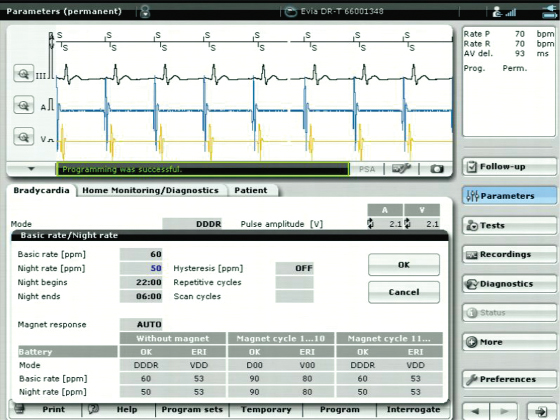
An option for “circadian response,” or “sleep rate,” is available in many devices (Fig. 8.8).2 This feature allows a lower rate to be programmed for the approximate time during which the patient is sleeping. A separate, potentially faster lower rate limit may then be programmed for waking hours. (For example, the lower rate limit may be programmed to 60 ppm during waking hours and 40 ppm during sleeping hours.) In some devices, this feature is tied to a “clock,” and the usual waking and sleeping hours are programmed into the device. In other devices, the sleep rate is also set on the basis of waking and sleeping hours, but verification by a sensor is required to allow rate changes to occur.
Fig. 8.8 Programmer screen from which the “Basic rate” and “Night rate” can be programmed. In this example the base rate is 60 ppm and the sleep rate is programmed to 50 ppm. Tied to the “clock” in the pulse generator the lower rate will change to 50 ppm at 22.00 h and back to 60 ppm at 06.00 h.
In rate-adaptive pacemakers and in dual-chamber devices capable of atrial tracking, an upper rate limit must also be programmed. The upper rate defines the fastest paced ventricular rate allowed. Determining the appropriate upper rate depends on the patient’s age, exercise requirements, and associated cardiac and noncardiac morbidities. From a programming standpoint, the total atrial refractory period (TARP), which is the post-ventricular atrial refractory period (PVARP) plus the atrioventricular (AV) interval, effectively determines the maximum achievable tracking rate (see Chapter 7: Timing Cycles). In dual-chamber rate-adaptive pacemakers, the upper rate limit may be a single programmable value, or two independently programmed values: one for maximum tracking rate and one for maximum sensor-driven rate (see Chapter 7: Timing Cycles).
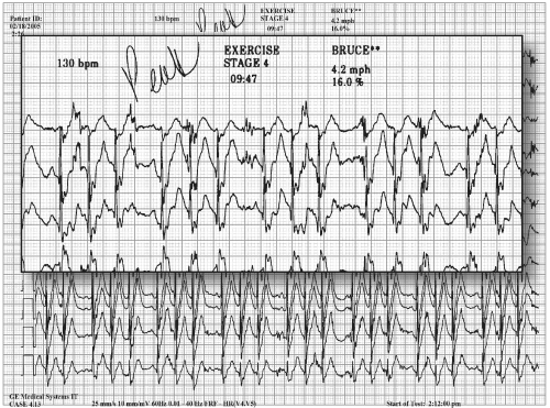
The nominal upper rate limit, i.e., the upper rate programmed by the manufacturer, is often in the range of 120–130 ppm. For many active individuals a more aggressive upper rate limit should be considered. In Chapter 9: Rate-Adaptive Pacing, we discuss exercise assessment for patients with rate-adaptive pacemakers. At times it is helpful to assess the patient’s rate during ambulatory monitoring, informal exercise3 or a formal treadmill exercise test.4,5 Symptoms present during pseudo-Wenckebach or 2 : 1 upper rate behavior inform programming the upper rate limit and other parameters that impact the upper rate (such as AV delay and PVARP). For example, if the patient has normal sinus node function but the upper rate limit is limited by the TARP, shortening the AV interval and/or the PVARP may be required (Fig. 8.9).
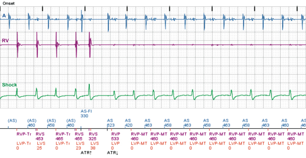
Fig. 8.9 Electrocardiographic tracing obtained during a treadmill exercise test in a 17-year-old patient complaining of sudden onset fatigue during intense exercise. In this example the patient had reached the programmed maximum tracking rate and displays pseudo-Wenckebach behavior. The sensor-indicated rate was not fast enough to prevent a significant alteration in V-V cycle length. The effective sudden decrease in ventricular rate paired with the irregular cycle length resulted in the patient’s exertional symptoms.
Programming Hysteresis, AV Search Hysteresis, Ventricular Pacing Avoidance Algorithms, and Sudden Bradycardia Response Algorithms
Hysteresis has been available for decades but remains a source of confusion. Hysteresis permits prolongation of the first paced escape interval after a sensed event. A ventricular pacemaker programmed at a cycle length of 1000 ms (60 ppm) and a hysteresis rate of 1500 ms (40 ppm) allows 500 ms more after a sensed QRS for another sensed QRS complex. Should another QRS complex not occur, the pacemaker returns to the programmed rate of 60 ppm, an escape interval of 1000 ms (see Chapter 7: Timing Cycles, Fig. 7.62), until once again a sensed event restarts the cycle. The advantage of hysteresis in a single-chamber pacing mode is the ability to maintain spontaneous AV synchrony if the intrinsic rate is below the lower rate limit. In patients with VVI pacing and pacemaker syndrome, hysteresis may prevent symptomatic retrograde ventriculoatrial (VA) conduction and increases the potential for intrinsic conduction.
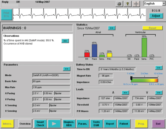
Several types of AV search hysteresis and ventricular pacing avoidance algorithms are programmable options in dual-chamber pacemakers (detailed in Chapter 7: Timing Cycles). The purpose of these algorithms is to minimize ventricular pacing to promote intrinsic ventricular conduction (Fig. 8.10). Minimizing RV apical pacing (i.e., avoiding pacing in nonresynchronization systems) lowers the risk of pacemaker-induced dysynchrony, and consequent atrial fibrillation and heart failure.6–8
Fig. 8.10 Programmer screen demonstrating that the pacing mode is “AAISafeR,” i.e. a ventricular avoidance pacing mode. The patient has been maintained in the AAI pacing mode 99.6% of the time monitored.
When programming AV intervals, it is reasonable to extend the AV interval to the maximum programmable value or, if available, to program algorithms that promote intrinsic conduction “on” in order to to assess intrinsic conduction (Fig. 8.11). If intrinsic AV nodal conduction is present, then algorithms to minimize ventricular pacing are activated. The often asked question is, “How long can the AV interval be extended before there are adverse consequences?” One study determined the maximal AR interval to be ≥230 ms before negative consequences were seen.9 We will frequently allow both paced (PAV) and sensed (SAV) intervals to extend to 300 ms. At longer intervals one needs to be certain that AV synchrony is not compromised. Occasionally, it is helpful to use echocardiographic techniques to optimize the AV interval in pacemaker patients. The goal of echocardiographic guidance is to optimize atrial contribution to ventricular filling and to minimize or at least limit diastolic mitral insufficiency. Marked prolongation of AR or AV intervals limits the upper tracking rate and may lead to more frequent episodes of pacemaker and/or pacemaker-mediated tachycardia as a result of effective uncoupling of atrial and ventricular activity.
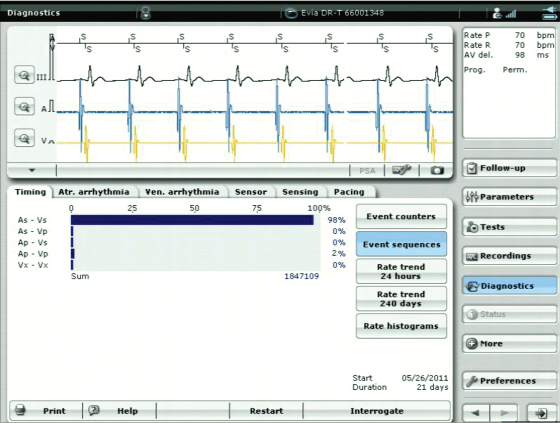
Fig. 8.11 Programmer screen that depicts the outcome of intended ventricular pacing avoidance, i.e., promotion of intrinsic atrioventricular conduction. This example summarizes a 21-day period during which intrinsic ventricular events were present 98% of the time.
Available AV search hysteresis and ventricular pacing avoidance algorithms are well designed and can be safely turned on in patients with evidence of some degree of intrinsic AV conduction.
In addition to minimizing ventricular pacing, there are patients who will benefit by allowing their native sinus activity to have preference over paced atrial activity. Several manufacturers have algorithms to maximize the presence of the native atrial rhythm.9 Criteria are programmed that periodically slow the paced rate to a preset level to determine whether or not sinus activity is present. If sinus activity is present, and if the intrinsic atrial rate meets criteria, atrial pacing is inhibited until the patient’s intrinsic rate falls to a rate that triggers atrial pacing (Fig. 8.12). Algorithms are also available to allow the converse, i.e., a preference for atrial pacing, to lower the risk of atrial fibrillation (Fig. 8.13).10
Fig. 8.12 Diagrammatic representation of an algorithm that allows intrinsic sinus rhythm to dominate when preset criteria for the algorithm are met. The rate is allowed to drop below the sensor-indicated rate and, if sinus activity is present within a specific rate “zone,” sinus activity is allowed until the rate falls to a specific rate and is maintained at or below that rate for a specified number of beats. If the intrinsic rate does not return to the preferred “rate zone” the pacing rate is gradually incremented back to the sensor-indicated rate.
(Reproduced with permission from Medtronic Adapta technical manual, pp. 5–25.)
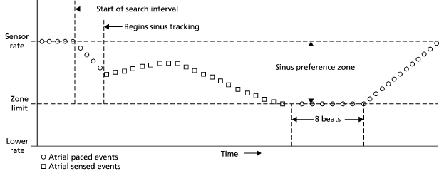
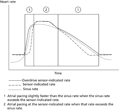
Fig. 8.13 If an atrial pacing preference algorithm is activated the pacemaker will increase the atrial pacing rate when intrinsic activity is sensed in an attempt to maintain a paced rhythm that is just faster than the intrinsic activity.
(Reproduced with permission from Medtronic Adapta technical manual, pp. 5–29.)
Another feature that may impact the pacing rate is one that responds to a sudden bradycardia. Most manufacturers have some algorithm whereby, if a significant decrease in heart rate occurs, the device intervenes with pacing at an increased rate in both chambers for a specific, programmed duration (Fig. 8.14). These algorithms were designed to treat vasovagal syncope, although their clinical utility has been modest. At the conclusion of the programmed duration of more rapid pacing, the pacing rate gradually returns to the programmed lower rate. This feature varies between manufacturers. In one algorithm the pacemaker monitors a drop in heart rate that must satisfy a programmable degree of rate decrease, the number of beats the rate must fall, and the duration of time over which the drop in rate occurs. The lower rate limit needs to be programmed slow enough to measure the magnitude of rate drop required for intervention at the faster paced rate. Setting the parameters in a very liberal manner may result in frequent triggering of the algorithm and annoying and unnecessary symptoms (Figs 8.14 and 8.15; see Chapter 7: Timing Cycles).11–13
Fig. 8.14 Electrocardiographic tracing that begins with a rate of slightly less than 60 ppm. Criteria are met for the sudden bradycardia response algorithm and are followed by pacing at a rate of 100 ppm. This will continue for a predefined length of time.
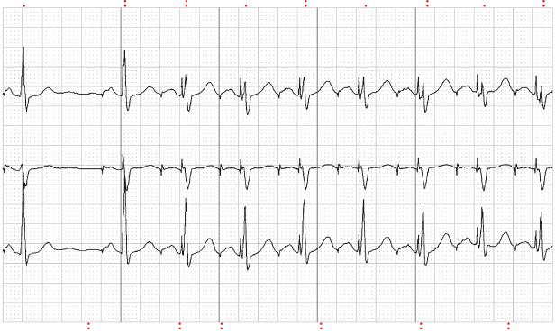
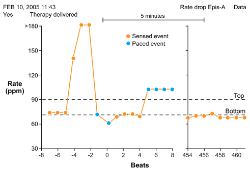
Fig. 8.15 Redrawn from a stored event from a patient with a pacemaker in place with Rate Drop Response (RDR™) programmed “on.” The patient initially has a sudden rapid intrinsic rhythm per the pacemaker diagnostics. The intrinsic rate then drops precipitously and meets RDR criteria. The algorithm then results in pacing at a rate of 100 ppm. When the duration of the RDR pacing “times out,” the stored event shows that the patient’s rate returns to a rate of approximately 70 ppm.
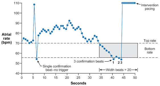
In another algorithm, therapy is triggered when pacing occurs at the programmed lower rate for the programmable consecutive number of “detection beats” (Fig. 8.16).14 The “antisyncope” algorithms interact with sensor use (Medtronic) and the programmed lower rate (Boston Scientific).
Fig. 8.16 Medtronic “Low Rate Detect.” When pacing occurs at the programmed lower rate for the programmable consecutive number of detection beats, therapy is triggered. Low Rate Detect may be used as a backup to the method in Fig. 8.15 if the sudden drop in rate varies between slow and fast.
Programming Output (Pulse Width and Voltage Amplitude)
Programming an appropriate pacemaker output is one of the most critical programming steps. There are two goals in programming output: (i) ensure reliable capture with an adequate safety margin, preferably measured in voltage (as opposed to pulse duration); (ii) maximize pulse generator longevity to the extent this is consistent with the first goal. This requires getting the best safety margin at a pulse duration that provides minimal energy drain from the battery.
Adjustment of output is performed to extend pulse generator life by reducing output and battery drain or to manage increased or increasing stimulation thresholds. Pulse generators provide significant flexibility in pulse width (0.05–1.9 ms) and voltage amplitude (0.5–8.1 V) (these values vary between manufacturers and to some degree between models of a given manufacturer).
With good implantation technique and low-threshold lead designs, e.g., steroid-eluting leads, it is common to program the voltage output to values of ≤2.5 V (the nominal voltage for many pacemakers). (The voltage amplitude program is also affected by the programmed pulse width, see later.) By programming the output at an efficient but safe level, the projected battery life can be increased significantly. A decrease in output can also be used to eliminate extracardiac (diaphragmatic or pectoral muscle) stimulation.
In some patients, thresholds may increase after implantation. Although a transient and mild increase in thresholds is not uncommon in the first 4–6 weeks after implantation, higher outputs can be programmed until thresholds return to a stable level. Although this threshold evolution is largely avoided with steroid-eluting leads, it is reasonable to program higher outputs for the first 2–3 months post-implantation. We generally leave output parameters at nominal values until the patient returns for threshold measurement and then subsequently reprogram to lower outputs. If an auto-capture algorithm is being used that will check stimulation thresholds on a relatively frequent basis and respond automatically to a loss of capture, it may not be necessary to leave the initially programmed output parameters at higher values. Available auto-capture algorithms are summarized in Table 8.3.
Table 8.3 Capture management algorithms.
| Biotronik | Atrial Capture Control (ACC) looks for intrinsic activity as evidence of noncapture. ACC can be programmed “on” or to Automatic Threshold Monitoring (ATM). When programmed “on” the device may adjust pacing amplitude in the atrium. Unlike VCC, ACC does not evaluate atrial capture on a beat to beat basis. Once the threshold is determined and amplitude set it will not run another threshold until designated scheduled search |
| Ventricular Capture Control (VCC) measures the capture threshold and adjusts pacing amplitude to accommodate for changes, eliminating the need for a 2 : 1 safety margin and reducing battery consumption. VCC can be programmed “on,” “off,” or automatic threshold monitoring (ATM). When “off” user must program and determine threshold values and outputs. When “on” or ATM, the device performs two steps: signal quality check (SQC), capture threshold search (CTS). When “on,” VCC also initiates continous capture control (CCC) which is a beat by beat assessment of ventricular capture on an ongoing basis and a back-up pulse in there is loss of capture | |
| Boston Scientific | Ventricular Automatic Capture feature checks on a beat-to-beat basis for the evoked response. If there is an evoked response, beat-to-beat mode continues at an output of 0.5 V above last measured threshold. If there is a loss of capture, the device delivers a backup safety pace at 1.5 V greater than previously measured threshold (up to 4.5 V). If there is a second loss of capture in two of four cardiac cycles, the device delivers another backup safety pace as described above. At this point, a confirmed loss of capture is declared and an Ambulatory Threshold Test is performed. Ambulatory Threshold Test is conducted every 21 hours or upon a confirmed loss of capture. The device performs an Ambulatory Threshold Test by starting at a voltage of 3.5 V and stepping down in 0.2 V decrements until reaching 1.0 V and in 0.1 V decrements thereafter. If the test is successfully completed, the device will return to beat-to-beat mode again pacing 0.5 V above last measured threshold. If test cannot be successfully completed, i.e., no loss of capture detected (decremented to lowest output of 0.1 V) or a measured threshold greater than 3.0 V, the device will enter Retry mode. In Retry mode, the device will pace at twice the previous measured threshold (minimum of 3.5 V and maximum of 5.0 V) |
| Not available on atrial channel; not available on high-voltage devices | |
| Medtronic | The Capture Management™ feature in Medtronic devices uses different capture verification methods for RV (evoked response), LV (LV pace induced RV sensing) and atrial (AV conduction [AVC] and atrial intrinsic suppression, i.e., atrial chamber reset [ACR]) chambers. These algorithms generally use sequences of three normal paces followed by a test pace, typically followed by a backup pace to avoid symptoms associated with these tests running while the patient is ambulatory |
| Capture Management generally operates by reducing pacing amplitude until capture is lost and then increase it again until capture is regained. Then, if programmed to adapt outputs rather than just monitor thresholds, output settings are adjusted above the measured thresholds according to the programmed safety margins. Capture Management nominally performs threshold measurements only once per day applying a programmable (nominal 2 : 1) voltage safety margin intended to cover circadian variations in threshold | |
| Sorin Medical | No autothreshold algorithms on atrial lead |
| AutoThreshold – Three programmable values: (1) Off; (2) Auto; and (3) Monitor. In Monitor the system will do all the regular testing but not change the programmed amplitude value. In Auto the assessment is made and the amplitude value changed accordingly. Every 6 hours the device enters a Wait phase. At minimum this is a set of 8-V cycles where the output is put to 5 V. The system then calibrates itself to differentiate between evoked potential and polarization. If the system successfully calibrates itself then a stepdown threshold is performed from 1.95 V to 0.15 V in 0.15-V increments. The last captured cycle is the threshold and the output is calculated with the minimum programmable output of 2.5 V in the USA (1.5 V OUS). The output determined will be in effect for 6 hours when the system performs the operation again. The only time there are backup pulses are during the calibration and threshold phases. There are no backup pulses during the 6-hour period | |
| St. Jude Medical | Ventricular Autocapture™ (VAC) algorithm is beat to beat capture verification and provides a 5.0-V backup pulse with loss of capture. The VAC safety margin added is 0.25 V. Atrial capture confirmation (ACap™ Confirm) is available in low- and high-voltage devices in addition to the VAC. CRT-D devices also have LV lead capture confirmation (LV Cap™ Confirm) and RV Cap™ Confirm algorithms in addition to the A Cap Confirm™ algorithm. A Cap™ Confirm, LV/RV Cap™ Confirm algorithms are not beat to beat capture verification, but rather a “threshold search” is performed every 8/24 hours and a safety margin is added which is algorithm specific |
High thresholds may be transient or permanent, and output programmability is useful in both situations. In patients with a transient threshold elevation, higher outputs can be used until thresholds return to a stable chronic level. In patients with chronically high thresholds, the pulse generator can be programmed to higher output to permit reliable pacing (albeit with reduced pulse generator longevity). Programming to higher outputs may be done to temporize until a solution is sought to achieve lower thresholds, or it may be the permanent solution, despite the additional battery drain, if there is some reason not to proceed with lead revision.
The output function (voltage or pulse width) that is reprogrammed to manage a rising threshold depends on the threshold value. Programming the pulse duration at or >1.0 ms (i.e., approaching rheobase, the lowest voltage threshold at an infinitely long pulse duration) provides little additional safety margin and results in high current and energy drain.15 If pulse duration testing defines a threshold >1.0 ms, increasing the output voltage while using a shorter pulse width is a better option.
Experts disagree about the optimal method to program the safety margin once the stimulation threshold has been established. Some devices will program or suggest programmable values after autothresholds are completed. Manual programming options that have been advocated include:
- Double the voltage amplitude
- Triple the pulse width
- Determine the capture threshold in microjoules and program the voltage amplitude and pulse width to achieve three times the threshold in microjoules. (This technique is rarely used with contemporary devices.)
At a given output voltage, if the pulse duration threshold is high, increasing the voltage is probably more useful. Otherwise, extending the pulse width even further may result in little gain, i.e., pulse duration beyond rheobase does not significantly alter capture threshold. Conversely, if pulse duration threshold is very low, i.e., in the range of 0.05–0.1 ms at a given output voltage, reducing the voltage and modestly prolonging the pulse duration may be considered. In general, programming at a pulse width close to the chronaxie (see Stimulation threshold in Chapter 1: Pacing and Defibrillation) minimizes battery drainage, and is preferred if an adequate safety margin can be found. Output programmability should not be a substitute for proper lead placement.
How much safety margin is enough, especially with contemporary leads? There is no universally agreed upon answer to this question. The safety margin in part depends on how often the threshold is checked and available options for intervening in the event of a threshold change. The frequency of threshold assessment ranges from the two extremes of with every beat with automatic algorithms to once a year with manual operator assessment.
In general, a larger safety margin is favored in patients who are pacemaker-dependent, placed on medications that may alter pacing thresholds, on dialysis, or who have metabolic abnormalities that may lead to wide swings in electrolytes and/or metabolic status. A larger safety margin is usually more important on the ventricular than the atrial lead so as to avoid asystole.
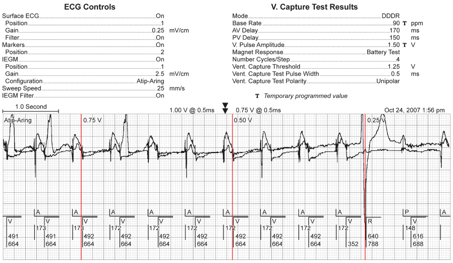
Determination of the stimulation threshold is a part of routine pacemaker follow-up. With autothreshold measurements, threshold assessment begins with selecting starting values for voltage and pulse width, and then observing the electrocardiogram and electrogram during output auto-decrement until capture is lost. The programmer for the specific device should provide clear directions on how to respond when capture is lost, e.g., move the programming head or release pressure from the programming screen (Fig. 8.17).
Fig. 8.17 Printout from pacemaker programmers displaying autothreshold testing. Ventricular voltage amplitude threshold test is performed with loss of ventricular capture at 1.0 V.
Despite the relative ease with which thresholds can be measured, it must be remembered that the risk of loss of capture includes not just asystole, but bradycardia-dependent tachyarrhythmias as well. Therefore, in pacemaker-dependent patients, equipment for external defibrillation should be available whenever thresholds are measured. Ideally, all thresholds should be measured on a temporary programming screen rather than a permanent screen, unless there is a specific reason to use a permanent screen. This is especially important when the device is near battery depletion, as programmability may be degraded.
Thresholds can also be determined by manually reprogramming the output to progressively smaller values until capture is lost. In the nonpacemaker-dependent patient, manual thresholds can be performed by first programming to the VVI mode and decreasing the rate until the patient’s intrinsic rhythm is observed. The pacing rate is then increased until it exceeds the intrinsic ventricular rate. Thresholds can be performed by using a fixed pulse width and decrementing the voltage amplitude or by using a fixed voltage amplitude and decrementing the pulse width. We generally program the pulse width to 0.5 ms and decrement the voltage. The point at which capture is lost is noted, and the threshold defined as the last voltage amplitude at which capture was maintained. Another rapid method for checking thresholds in the nondependent patient uses simultaneous changes in rate and output variables. For example, with the pacemaker programmed to VVI at 40 ppm, if the intrinsic rate is 70, the next programming step could include VVI at 80 ppm, and very low output variables, e.g., voltage amplitude of 1.0 V and pulse width of 0.12 ms. If pacing is re-established, the stimulation threshold is ≤1.0 V, 0.12 ms. If capture is not re-established at 1.0 V and 0.12 ms, one of these two variables can be increased until capture occurs. Whether one increases pulse width or voltage amplitude for determination of stimulation threshold is in large part personal bias.
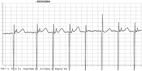
Other methods of assessing pacing safety margin have been available for years.16,17 One manufacturer incorporates a Threshold Margin Test with magnet application.16 With this technique, magnet application results in a rate of 100 ppm for three beats, followed by asynchronous pacing at the programmed rate. The first and second pacing artifacts at a rate of 100 ppm are delivered at the programmed pulse duration. The third pacing artifact is delivered at 75% of the programmed pulse duration. Loss of capture on the third beat indicates a narrow margin of safety (Fig. 8.18).
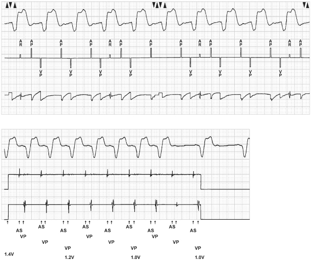
Fig. 8.18 Electrocardiographic tracings from a patient with a VVI Medtronic pacemaker programmed to a rate of 70 ppm. The pacemaker is capable of a Threshold Margin Test (TMT) during magnet application. With magnet application the rate goes to 100 ppm. The first pacing artifact fuses with the QRS and it is difficult to tell if there is a QRS complex present. However, there is a definite “T” wave that follows so by definition, “if there is repolarization there had to be depolarization.” The second artifact results in definite capture. At the third pacemaker artifact there is failure to capture and a native QRS follows approximately 240 ms later. It is on the third output after magnet application when the pulse width is decreased to 80% of the programmed value.
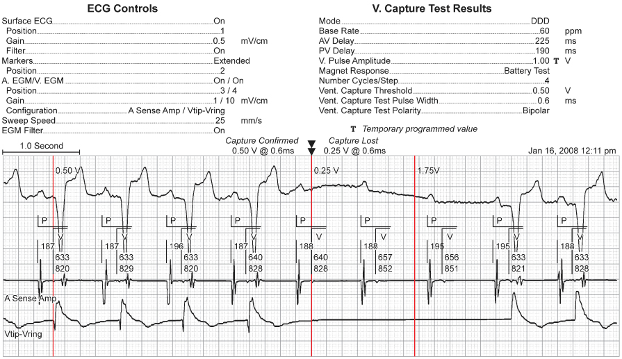
Features that allow the pacemaker to automatically adjust output based on threshold changes conserve battery consumption, prolong device longevity, and protect patients from failure to capture due to increasing stimulation thresholds.18–22 Automatic output adjustment and management is available in most devices and, as with any algorithm, operational features vary between manufacturers. The proprietary AutoCapture™ system confirms capture on a beat-by-beat basis by monitoring the “evoked response” (ER) associated with the ventricular pacing output. The “evoked response” is deflection on the intracardiac electrogram that indicates that capture has occurred.21,23 To detect the ER signal, a bipolar, low polarization pacing lead should be used. Each paced ventricular complex is assessed for capture by monitoring the ER signal. When no ER signal is detected, the AutoCapture system delivers a 5-V backup safety pulse within 80–100 ms. This backup safety pulse functions as the “safety margin.” With two consecutive loss-of-capture events followed by backup safety pulses, the AutoCapture system automatically increases the output of the primary pacing pulse until capture is regained from the primary pacing pulse (Fig. 8.19). At the beginning of this increment, the first paced event is increased by 0.25 V. If capture is not confirmed with this paced event, the pulse amplitude continues to increase in 0.125-V steps* until capture is verified from the primary pacing pulse for two consecutive paced events. Once verification occurs, the pacemaker automatically initiates a threshold search. If capture for two consecutive events is not confirmed by the time the pacemaker output reaches 3.875 V, the pacemaker automatically reprograms to 4.5 V and 0.5 ms pulse width, or “high output mode” pacing.
Fig. 8.19 Ventricular AutoCapture threshold test demonstrating loss of capture at 0.25 V at 0.6 ms. Capture was confirmed at 0.5 V at 0.6 ms. Following loss of capture the output returns to 1.75 V.
(From the collection of and with the permission of Paul A. Levine, MD, FHRS.)
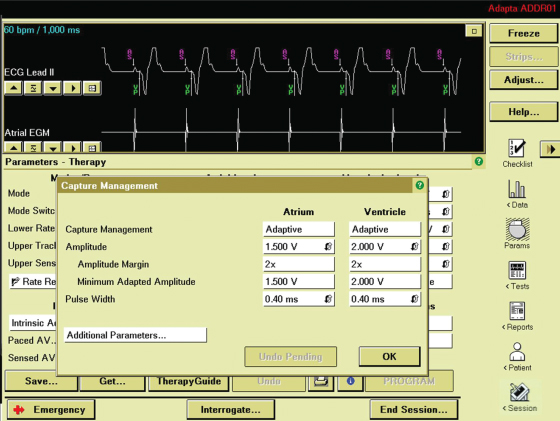
Capture management algorithms vary a great deal between manufacturers. They may be responsible for some unusual electrocardiographic findings and, like any programmable feature, the provider needs to know and understand the nuances of the specific algorithm being employed (Fig. 8.20).
Several manufacturers have auto-capture management algorithms available for the atrial channel as well.
Because output adjustment is critical for both extremes, i.e., for maintaining an adequate safety margin and for prolonging battery longevity, automatic regulation of output has become a fairly standard feature and is used with increasing frequency.
Programming Sensitivity
All pulse generators filter then sense the intracardiac electrogram delivered by the pacing leads. For atrial and ventricular sensing, the R and P waves must have a sufficient amplitude (millivolts) and slew rate (dV/dt) for proper sensing to occur. The programmed sensitivity is the smallest amplitude signal that the device recognizes (Figs 8.21 and 8.22). Events sensed on the atrial channel are defined as P waves, those sensed on the ventricular channel as R waves. For cardiac resynchronization therapy (CRT) devices there is also discrimination between sensing on the RV lead and sensing on the LV lead. Nominal ventricular sensitivity is usually in the range of 1.2–2.5 mV, and nominal atrial sensitivity is usually in the range of 0.5–1.2 mV. Although the amplitude of intracardiac R or P waves may be adequate at implantation, they may change over time due to metabolic or drug effects, myocardial damage, or lead dislodgment. Different intrinsic foci may not have different amplitudes on the sensing channels, so that extrasystoles may be undersensed despite normal sensing of normal rhythm, and vice versa.
Fig. 8.21 R-wave amplitude test. It is displaying the Ventricular Sense Amplitude electrogram. The top tracing is the surface ECG. The test results are shown in the upper right and the various values and settings for the actual ECG and EGM recording are in the upper left.
(From the collection of and with the permission of Paul A. Levine, MD, FHRS.)
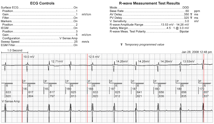
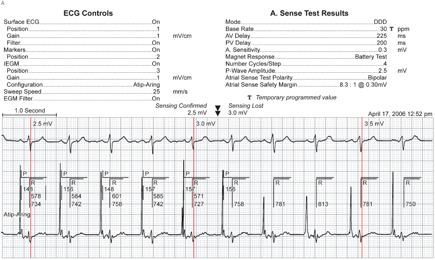
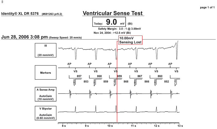
Fig. 8.22 (A) Trial sense test from a patient with a dual-chamber pulse generator. It is being run with the surface ECG, the event markers and the bipolar (Atip-Aring) electrogram being simultaneously displayed. Note the lack of P markers at the temporarily programmed sensitivity of 3.0 mV. Hence, the sensing threshold is the previous more sensitive setting at which there was consistent sensing for the number of cycles programmed for the test (4–10) and this value is shown in the data at the upper right. (B) Semiautomatic “Ventricular Sensing test.” Under the central box with the new value, i.e., 9 mV, there is a display of the results the last time that this test was performed, at which time it was >12.5 mV.
(From the collection of and with the permission of Paul A. Levine, MD, FHRS.)
Programming sensitivity to a smaller value increases the sensitivity of the amplifier, so that a smaller amplitude signal will be sensed as an event. (The terminology is confusing because the amplifier is made more sensitive as the number decreases, i.e., 1.25 mV is more sensitive than 2.5 mV.)
The sensing threshold should be determined during routine pacemaker follow-up and can be accomplished in multiple ways. Manual sensing thresholds can be obtained by programming the pacemaker to progressively less sensitive values until there is failure to sense. (Sensing thresholds could also be determined by altering sensing values during programming to a triggered pacing mode, i.e., AAT or VVT.)
Automatic sensitivity adjustment is available in many pacemakers. Autosensing adjusts sensitivity on the basis of amplitude of the intrinsic waveform.24,25 However, the method of dynamically altering sensitivity after paced or sensed events, available in implantable cardioverter-defibrillators (ICDs) for generations of devices, is now used in pacemakers; see Sensing sources). The purpose of automatic sensitivity is to prevent both oversensing and undersensing (Fig. 8.23). Although not as critical clinically as automatic output management, automatic sensing has merit and is used with increasing frequency. As noted early in this chapter, determination of sensing threshold via the programmer is often available.
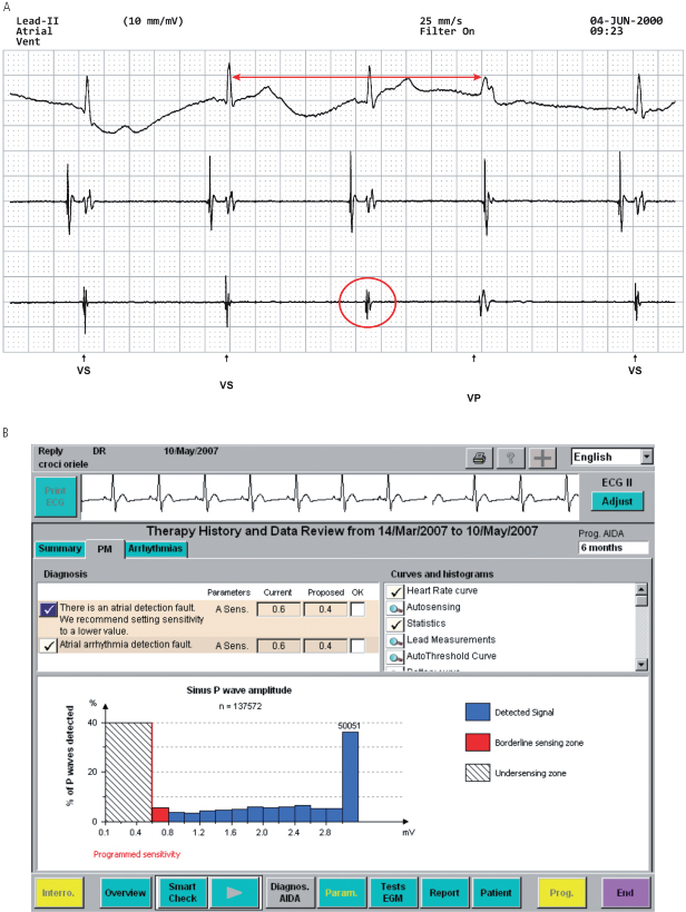
Fig. 8.23 (A) Electrocardiographic tracing from a patient with a dual-chamber pacemaker programmed to VVI mode at 30 ppm. (Top tracing, surface ECG; second tracing, atrial electrogram; third tracing, ventricular electrogram; marker channel at the bottom of the tracing.) Note that third QRS has no marker channel notation and is followed by a ventricular paced (VP) event. Measuring backward from the VP event by 2000 ms (30 ppm) it coincides with the prior ventricular sensed (VS) event. The measured R wave equaled 2 mV. When programmed to unipolar sensing configuration, the R wave measured 6 mV. Had an automatic sensitivity algorithm been programmed “on” this abnormality should be reprogrammed automatically avoiding any clinical sequelae. (B) Programmer screen displaying device diagnosis of atrial undersensing with sensing histogram. Based on this diagnosis the pulse generator proposes that atrial sensitivity be reprogrammed from 0.6 to 0.4 mV.
The differential diagnoses for sensing abnormalities and approach to correcting such problems are discussed in Chapter 10: Troubleshooting.
Polarity Programmability
Polarity programmability is available on most pacemakers with bipolar configuration. It allows programming from unipolar to bipolar functions. (In some dual-chamber pacemakers, the polarities of the atrial and ventricular channels are independently programmable; in others, they are not.) This feature is helpful in patients who have myopotential or electromagnetic inhibition in the unipolar mode, but not in the bipolar mode. Unipolar and bipolar electrograms have different characteristics, and programming from one polarity to the other may eliminate the sensing of an unwanted electrogram or interfering signal. It is possible but improbable that sensing in one polarity configuration will be superior to that in the other (Fig. 8.23).
Polarity programmability may be helpful in a patient with a lead fracture or inner insulation failure. If the conductor to the ring electrode is fractured, reprogramming from bipolar to unipolar mode may restore effective pacing by using the intact conductor of the pacing lead and bypassing the damaged one (Fig. 8.24). This alternative should usually be considered a temporary measure, because whatever force resulted in fracture of one conductor may have damaged the other. In an increasing number of pulse generators, a change from bipolar to unipolar pacing configuration may be triggered automatically when a sudden change in impedance is detected during bipolar pacing, providing this programmable option is activated (Fig. 8.25).26,27
Fig. 8.24 Electrocardiographic tracings from a patient with a VVI pacemaker. (A) In the bipolar configuration, there is intermittent failure to capture. Capture is demonstrated only with the first two pacing stimuli. (B) Programmed to the unipolar configuration at the same pulse duration and voltage, the pacemaker demonstrates consistent capture.
(From Hayes DL. Programmability. In: Furman S, Hayes DL, Holmes DR Jr, eds. A Practice of Cardiac Pacing, 3rd edn. Mount Kisco, NY: Futura Publishing Co., 1993:635–63, by permission of Mayo Foundation.)
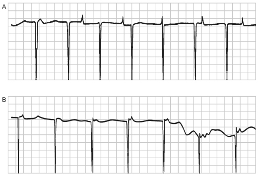
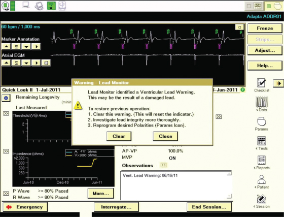
Fig. 8.25 Programmer screen with a “Lead Monitor” warning. If the lead monitor is programmed to adapt to a certain change in lead impedance, the pulse generator will reprogram from bipolar to unipolar pacing configuration.
Refractory and Blanking Periods
Refractory and blanking periods are described in detail in Chapter 7: Timing Cycles. In brief, a refractory period can be defined as an interval during which a given sensing circuit does not respond to sensed events except to increment mode-switching counters. In contrast, events that occur during a blanking period are completely ignored, and not sensed at all.
Single-Chamber Pacemakers:
Refractory period programming may be necessary in a variety of clinical circumstances. In the VVI mode, the ventricular refractory period (VRP) is the interval during which the ventricular sensing circuit does not respond to sensed events. The first portion of the VRP is usually a ventricular blanking period during which ventricular sensing is disabled after paced, sensed, and refractory sensed ventricular events. Depending on the pacemaker, the ventricular blanking period may be fixed, programmable, or dynamic. Refractory period programming in single-chamber pacing is not commonly required but can be advantageous in some situations. Lengthening of the VRP may help prevent sensing of afterpotential depolarizations, T waves, or premature ventricular contractions. If the refractory period is too long, a closely coupled ventricular electrograms may be undersensed and a pacemaker stimulus could potentially fall on the T wave of the unsensed beat. In this circumstance, shortening the VRP would be appropriate.
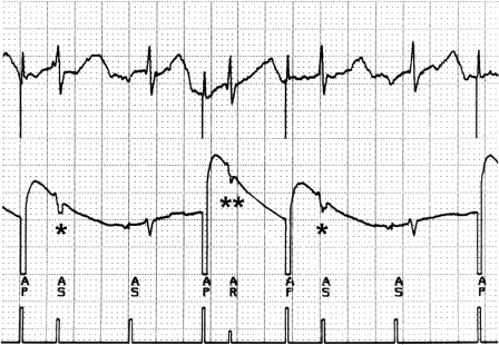
When atrial pacing in the AAI mode, a refractory period that exceeds the intrinsic PR interval is desirable to avoid inhibition of atrial pacing as a result of far-field R-wave oversensing (Fig. 8.26).
Fig. 8.26 Tracing obtained from a patient with a pacemaker programmed to the AAI mode. (Top, surface electrocardiogram; middle, atrial electrogram; bottom, marker channel.) Each atrial paced (AP) event is followed by an event that is labeled as an atrial sensed (AS) event. These events actually represent sensing of the QRS on the atrial sensing channel. The two events labeled with (*) fall outside the atrial refractory period and alter the timing cycle. The event labeled AR (**) occurs slightly earlier relative to the atrial pacing artifact that precedes it and falls in the atrial refractory period.
Dual-Chamber Pacemakers:
Refractory periods in dual-chamber, dual-sensing devices are more complex than single-chamber because the events and timing cycles in one channel affect those in the other. The refractory periods in the ventricular channel behave the same as during single-chamber sensing. The refractory periods in the atrial channel are quite different. After an atrial stimulus or a sensed atrial event, the initial portion of the atrioventricular interval (AVI) is the atrial blanking period. During this interval, atrial sensing does not take place. Depending on the pacemaker, the atrial blanking period is fixed, programmable, or dynamic, i.e., varying in relation to the strength and duration of the atrial event. (Blanking period programmability is summarized in Table 8.4.)
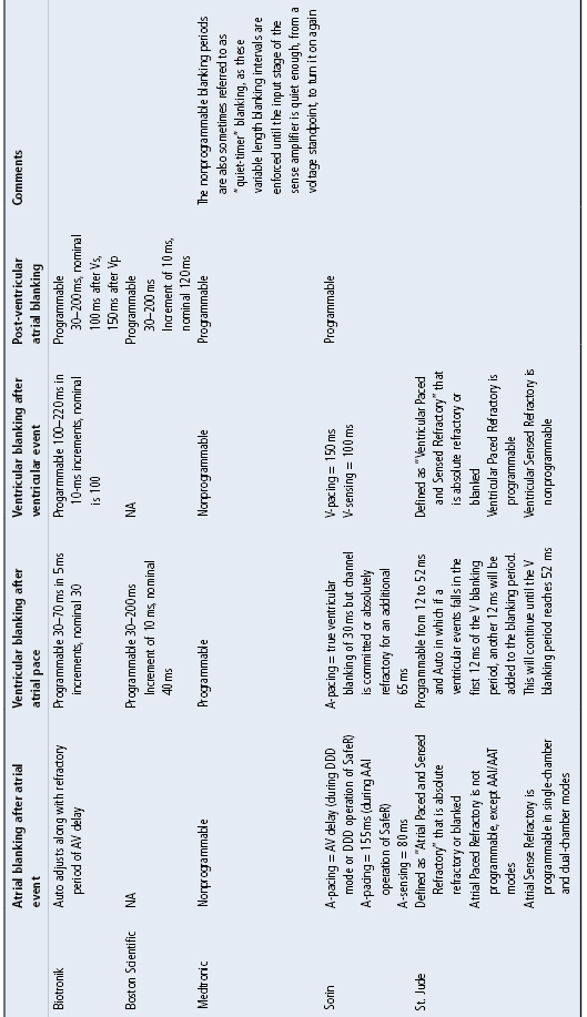
Table 8.4 Manufacturer-specific blanking characteristics.
A ventricular blanking period is also initiated with a sensed or paced atrial event. The intent of this interval is to avoid sensing the electronic event of one channel in the opposite channel (“crosstalk”). The blanking period is usually programmable (Table 8.4). It may be desirable to prolong the blanking period to prevent crosstalk (Fig. 8.27). It may be necessary to shorten the blanking period if ventricular extrasystoles are sensed during this period, because the result could be pacing during the early portion of ventricular repolarization. Shortening the blanking period should diminish the likelihood of the QRS occurring within the blanking period.
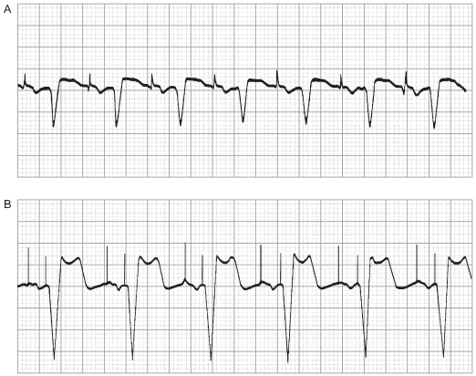
Fig. 8.27 (A) Electrocardiogram from a patient with a DDI pacemaker programmed to a rate of 86 ppm, atrioventricular (AV) interval of 165 ms and a blanking period of 13 ms. The interval from the atrial pacing stimulus to the intrinsic QRS complex is actually 220 ms. This abnormality occurs because the atrial output is sensed on the ventricular sensing circuit and inhibits ventricular output. AV nodal conduction is intact with a first-degree AV block. (B) When the blanking period is lengthened to 45 ms, crosstalk is prevented. A ventricular pacing stimulus occurs 165 ms after the atrial pacing stimulus, i.e., at the programmed AV interval.
(From Hayes DL. Programmability. In: Furman S, Hayes DL, Holmes DR Jr, eds. A Practice of Cardiac Pacing, 3rd edn. Mount Kisco, NY: Futura Publishing Co., 1993:635–63, by permission of Mayo Foundation.)
The atrial sensing amplifier remains refractory for the remainder of the AVI plus the programmed PVARP.
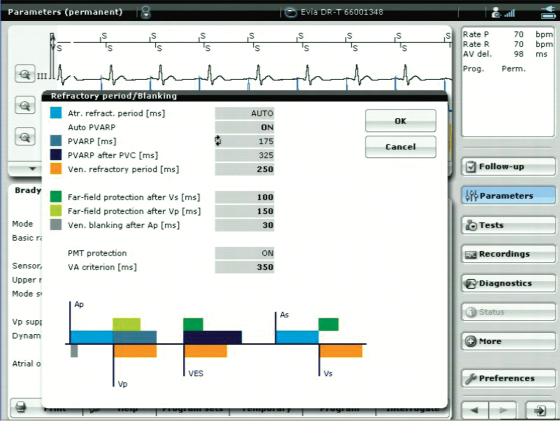
The first portion of the PVARP disables atrial sensing after paced, sensed, and refractory sensed ventricular events, i.e., the post-ventricular atrial blanking period (PVAB). Once again, this interval may be fixed or programmable, depending on the pacemaker (Fig. 8.28).
Fig. 8.28 Programmer screen which notes auto-PVARP to be “on.” In addition, all of the refractory and blanking periods are listed and diagrammed. The diagram helps the clinician programming the device to better understand the interactions between the refractory and blanking periods and the difference in timing following a ventricular extrasystole (VES). After the VES, the PVARP is extended, dark blue.
Sensed events in the nonblanked portion of the TARP (TARP is composed of the AV interval and PVARP) are used for mode switching. Excessive atrial blanking may prevent mode switching, particularly at rapid ventricular rates. Minimal PVAB periods are preferred in patients at risk for 2 : 1 conduction of atrial flutter.
Programmable flexibility of the PVARP is especially important because of its role in preventing endless-loop tachycardia (ELT) (Fig. 8.29).28,29 Because ELT can occur only when the PVARP is shorter than the retrograde (VA) conduction time, this is an especially important interval. However, not all patients have intact VA conduction and some have short retrograde conduction times. Algorithms to detect and interrupt ELT do so by automatically lengthening the PVARP or the AVI, or both periodically so that the retrograde P wave will fall into a refractory period and thus not be tracked (Fig. 8.30) (see Chapter 7: Timing Cycles).
Fig. 8.29 Pacemaker mediated tachycardia from a CRT device; tracing from remote-monitoring. An atrial sense event (AS) occurs early and appears to alter timing that results in a sustained PMT. In this example the designation “MT” indicates the device is tracking at the maximum tracking rate allowed by the programmed settings.