Physics of Ultrasound and Physics: Behind the Knobs
Peter Rozman1
Michael G. Licina2
James D. Thomas2
Robert M. Savage2
1OUTLINE AUTHOR
2ORIGINAL CHAPTER AUTHORS
▪ KEY POINTS
A more thorough understanding of the physical principles of ultrasound effectively permits the acquisition of higher quality echocardiographic data on which the perioperative team may base their clinical decisions.
Sound can be classified as subsonic or infrasonic (less than 20 cycles/s), audible sound (20 to 20,000 cycles/s), and ultrasound (greater than 20,000 cycles/s).
Echocardiography is based on the electrical conversion (by piezoelectric crystals) of reflected ultrasound waves (greater than 20,000 cycles/s frequency) from structures and blood flow within the cardiovascular system.
Sound waves are characterized by the properties of frequency (f) or number of cycles per second, amplitude (A or loudness), and wavelength (λ) or distance between two adjacent ultrasound cycles.
Using the average propagation velocity of ultrasound through tissue (c) or 1,540 m/s, the relation between frequency (f) and wavelength (λ) is characterized as:
c (1,540 m/s) = f (cycles/s) × λ (mm)
or
λ (mm) = c (1,540 m/s)/f (cycles/s).
Resolution is the ability to distinguish two points in space and is inversely related to wavelength and directly related to frequency. It follows that the longer the wavelength, the less the frequency, the less the resolution, but the greater the tissue penetration. Ultrasound waves that are reflected from structures and blood moving toward the transducer compress the wavelength and increase the frequency. The magnitude of this difference is referred to as the Doppler shift and is determined by the velocity and direction of the structure reflecting the ultrasound beam. Processing of this Doppler shift information by the ultrasound platform results in the two-dimensional (2D) image, as well as color flow, pulsedwave, and continuous wave (CW) Doppler information.
I. INTRODUCTION
Echocardiography is the use of sound to produce an image of the heart and/or surrounding structures.
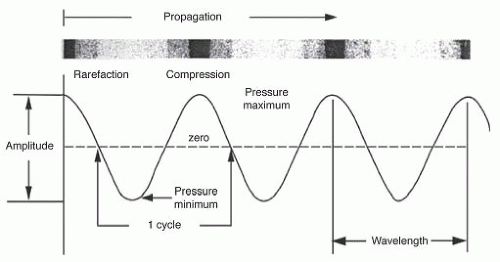
Sound is a mechanical vibration in a physical medium which stimulates hearing and travels in the form of a propagating wave that can be expressed graphically as a sine wave (Fig. 1-1).
Amplitude (A), which is measured in decibels (dB), is the maximal compression of particles above the baseline and equates to loudness in a sound wave.
Decibels are logarithmic units based on a ratio of the measured value (MV) to the reference value (RV), so dB = 20 log (MV/RV), which allows for compression of a large range of values into a small range.
Intensity (I) is the level of sound energy in an area of tissue and is proportional to the amplitude of the sound wave squared.
Wavelength (λ) is the distance between two adjacent areas of maximal compression, while frequency (f or Hz) is the number of wavelengths per unit time.
The propagation velocity (c) equals the wavelength times the frequency and is relatively constant in sound waves in the human heart (1.5 × 10³ m/s).
Wavelength is important in image resolution, the ability to distinguish two points in space, because image resolution is no greater than 1 or 2 wavelengths and the depth of penetration of the ultrasound is directly proportional to it.
Acoustic impedance, the process of sound traveling through a medium, equals the density of the medium times the velocity of the sound and is responsible for reflection when sound beams travel between two tissues.
Reflection occurs when a sound wave reaches a boundary between surfaces with different acoustic impedances, and specular reflections occur on smooth surfaces.
Refraction is the change in direction of a sound wave as it travels between these surfaces and occurs when propagation speeds differ and the angle between the wave and the surface is oblique, causing imaging artifacts.
Scattering occurs when waves reflect off small, irregularly shaped objects.
Attenuation is the loss of the ultrasound wave and is directly related to the distance traveled.
Absorption is the conversion of ultrasound wave energy to another form of energy.
Sound can be classified as subsonic or infrasonic, audible sound, and ultrasound.
Ultrasound has a frequency greater than 20,000 Hz, can be directed in a beam, obeys wave properties, and is reflected by small objects.
II. GENERATION OF ULTRASOUND BEAM: PIEZOELECTRIC EFFECT
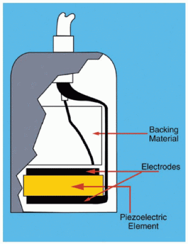
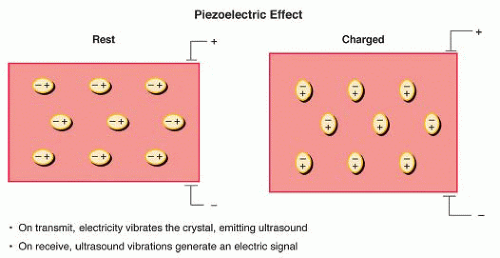
When a cut plate of quartz is subjected to mechanical stress, it will develop an electrical charge on its surface (Fig. 1-2), which is known as the pressure electric, or piezoelectric, effect (Fig. 1-3).
If a crystal is subjected to an alternating electric current, it will generate ultrasonic sound waves, forming the basis of ultrasonography.
III. IMAGING WITH ULTRASOUND
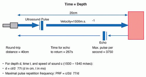
Due to the predictable time-distance relationship for ultrasound within the body (1,540 m/s), distances are easily determined given echo return times (Fig. 1-4).
The pulsed repetition frequency (PRF, in kHz) is approximated as 77/d (Fig. 1-4).
A. Wave interaction with tissues and organs
The amount of reflection that occurs at the tissue boundaries and interfaces is determined by the relative change in acoustic impedance.
Lateral dimensions greater than one wavelength act as specular reflectors, with an optimum angle occurring when the sound beam is perpendicular to the transducer.
Poor echo images occur due to dropout (the angle is greater than or less than 90 degrees) and scattering (lateral dimensions less than a wavelength).
Refraction allows enhanced images through acoustic lenses that focus the beam, but can also cause a “double image” artifact.
Conversion of ultrasound energy to heat, a form of absorption, results in attenuation, which has a direct relationship to frequency.
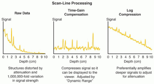
Due to the variances in returning signal strengths, a logarithmic compression, also called “time-gain compensation,” followed by differential amplification is necessary (Fig. 1-5).
IV. TRANSDUCERS
A transducer consists of the piezoelectric element, electrodes, case with insulation, and backing material.
A transducer is in receiver mode approximately 99% of the time,2,5,6 and can detect a wavelength signal that is less than 1% of the original.4,7
The electrodes stimulate and conduct electric current in and from the piezoelectric element.
The matching layer (faceplate), the layer between the esophagus and the piezoelectric element, causes the majority of the ultrasound to be transmitted instead of reflected, and possesses an acoustic lens to focus the beam.
The case and insulation protects from electric noise and prevents electric shock, while the backing material improves the picture quality by shortening the pulse duration and spatial pulse length.
Pulse wave Doppler uses a single piezoelectric crystal, while CW Doppler uses two.
V. WAVE FRONT CHARACTERISTICS
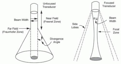
An unfocused beam travels in a column in its near field, or Fresnel zone, of which the length is directly proportional to the transducer’s diameter and inversely related to its wavelength (FN = D2/4λ) (Fig. 1-6).
In its far field, or Fraunholfer zone, the beam diverges in a manner that is directly proportional to the wavelength and inversely proportional to the transducer’s diameter (divergence angle = 1.22λ/D)4-6 (Fig. 1-6).
Focused zones can be manipulated by making the transducer lens concave or electronically focusing the beam, improving near field image resolution but worsening far field resolution (Fig. 1-6).
Axial (oriented along the length of the beam), lateral (side-to-side), or elevational (along beam thickness) resolutions exist, where axial is the most precise.
VI. REVIEW OF CONCEPTS
Wave energy exists as kinetic energy in the form of particle motion and as potential energy in the form of tissue compression and rarefaction.
Waves are characterized by the inverse relationship between wavelength and frequency.
A high frequency transducer will provide better resolution, while a low frequency transducer will provide better penetration.
Imaging ultrasound pulses must be extremely short, while Doppler pulses must be longer.
A. Resolution
Axial (or longitudinal, radial, range, depth) resolution distinguishes between two structures that are close to each other and front to back and depends on transducer frequency, bandwidth, and short pulse length.
Lateral resolution is the shortest distance that can exist between two structures while still producing two distinct echoes, equals beam diameter, and will vary with depth.
Temporal resolution is the ability to accurately locate moving structures at an instant in time and is affected by the number of pulses per scan line, the imaging depth, the sector size, and the line density.
VII. ULTRASOUND INSTRUMENTS AND IMAGING MODALITIES
A. A-, B-, or M-mode echocardiography
A- or B-mode echoes can determine distances between the transducer and the reflective surface, and the intensity of the reflected ultrasound.
A-mode echoes note intensity by the height of the oscilloscope’s electric signal, while B-mode echoes note intensity by varying brightness at the reflection point.
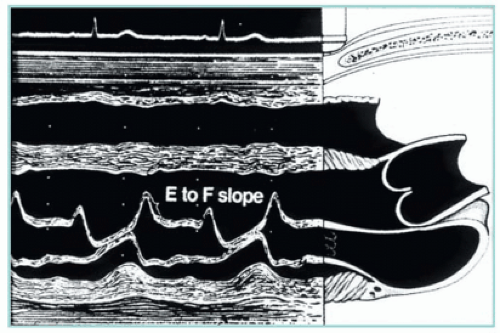
M-mode provides a time reference for B-mode, and a single crystal is used in both modes (Fig. 1-7).
B. Two-dimensional echocardiography
Image generation results from information from a fan-shaped sector of about 100 B-mode scan lines, with each ultrasound sweep of this plane occurring about 60 times/s.4,6
The earliest displays, which resembled oscilloscopic displays, made interpreting moving structures almost impossible to interpret, resulting in the creation of M-mode displays, with wave strength displayed vertically, and temporal variation horizontally.
M-mode imaging has a higher sampling rate than 2D imaging.4,7
Stay updated, free articles. Join our Telegram channel

Full access? Get Clinical Tree


