Physics of Echocardiography
James D. Thomas
Michael G. Licina
Robert M. Savage
Echocardiographic imaging relies on the reflection of ultrasound waves from structures within the cardiovascular system. This chapter will outline the physical principles of sound wave mechanics, ultrasound generation, transmission, reflection, and reconstruction, along with applications of Doppler echocardiography. Important concepts will be reinforced through repetition of principles fundamental to a practical understanding of clinical ultrasound. It is hoped that by understanding the basics behind image production, the intraoperative echocardiographer will have a better understanding of how to apply this technology in a variety of clinical settings.
KEY CONCEPTS
Echocardiography is the use of sound waves to produce an image of the heart and/or surrounding structures. Sound is a mechanical vibration in a physical medium, such as air, water, or tissue, which when stimulating the auditory apparatus produces the sensation of hearing. Sound travels through a medium in the form of a propagating wave. In this wave, there are areas in which the particles in the medium are either compressed or widened (areas of rarefaction). Sound can be expressed graphically as a sine wave (Fig. 1.1).
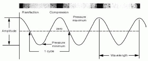 FIGURE 1.1. Schematic Diagram of a Sound Wave |
The height above or below the baseline represents the degree of particle compression and rarefaction, respectively. Amplitude (A) is the maximal compression of the particles above this baseline and is described in terms of decibels (dB). Amplitude equates to the loudness of the sound wave. It is the changes in amplitude that produce the gray, 2-D echocardiographic images.
Decibels are logarithmic units based on a ratio of the measured value (MV) to a reference value (RV) so dB = 20 log (MV/RV). Thus, a ratio of 10,000 to 1 is 80 dB and a ratio 2 to 1 is 6 dB. The advantages of using the decibel scale are that a very large range can be compressed into a smaller number of values and that low amplitude (weak) signals can be displayed alongside high amplitude (strong) signals. This compression, using the dB scale, is important in echocardiographic signal processing because amplitude measurements are the basis for 2-D echocardiography views.
Intensity refers to the level of sound energy in an area of tissue. This concept is represented as
Intensity (I) (watts / cm2) = Power (watts) / beam area (cm2)
Intensity is proportional to the amplitude of the ultrasound wave squared.
I ˜ A2
A higher ultrasound wave amplitude will cause greater intensity and thus a greater chance of tissue injury. Remember that lithotripsy uses high-intensity ultrasound waves to destroy renal calculi, whereas echocardiography uses low-intensity ultrasound waves.
Wavelength (λ) refers to the distance between two adjacent areas of maximal compression. The number of wavelengths per unit time is the frequency of the wave (f). Frequency may be expressed as cycles per second also called hertz (Hz). Wavelength (λ) times the frequency (f) is equal to the propagation velocity (c) of the wave as expressed by the formula:
c = f × λ
where c = propagation velocity
λ = wavelength
f = frequency
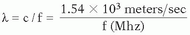
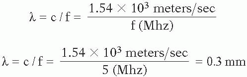
Because the propagation velocity of sound waves in human tissues of the heart is relatively constant—1540 meters/second or 1.5 × 10³ meters/sec—the wavelength is inversely related to the frequency of the sound wave and may be calculated as:
Resolution is the ability to distinguish two points in space and is determined by wavelength. Wavelength is important in echocardiography because image resolution is no greater than 1 or 2 wavelengths and the depth of penetration of the ultrasound wave is directly proportional to its wavelength. The longer the wavelength, the lower the resolution and the greater the tissue penetration. It is the changes in frequency that form the basis for Doppler echocardiography.
Acoustic impedance is the process of sound traveling through a medium; it is defined by the density of the medium times the velocity of sound that travels through that medium. As sound passes through a homogenous substance, it travels in a linear fashion. However, when the sound wave reaches an interface between two tissues with differing densities (acoustic impedances), part of the sound beam is reflected back to the source. The amount of reflection is dependent upon the differences in the acoustic impedances of the two tissues. Acoustic impedance is represented as
z = p × v
where p is the density
v is the velocity
Reflection occurs when an ultrasound wave reaches a boundary between two surfaces of differing acoustic impedances and a proportion of the wave is reflected back along the ultrasound beam path to the transducer. A greater acoustic impedance causes a greater amount of the ultrasound beam to be reflected. Reflections off a smooth surface, such as a mirror, are called specular. With specular reflections, most of the ultrasound waves are reflected and very little of the wave continues distal to this interface.
Refraction is the change in direction, or bending, of an ultrasound wave as it travels through mediums of differing acoustic impedances. It occurs when there are different propagation speeds and an oblique angle between the ultrasound beam and the surface interface. These changes in ultrasound beam direction by refraction can lead to the formation of imaging artifacts. Changing the ultrasound transducer angle to allow a 90° angle between the ultrasound beam and the surface interface can minimize the possible formation of artifacts; this minimizes the refraction.
Scattering is a type of reflection that occurs when ultrasound waves strike small or irregularly shaped objects, such as red blood cells. The reflected waves are dispersed in many different directions and are much weaker than specular reflections.
Attenuation is the loss of the ultrasound wave as it travels through tissues. It is the loss of intensity and amplitude. It is directly related to the distance the wave front travels.
Absorption occurs when ultrasound wave energy is converted to another energy form, such as heat or mechanical vibrations. Absorption is directly related to ultrasound frequency—the greater the frequency the better the absorption. In soft tissue, absorption is the primary cause of attenuation.
Sound can be classified as subsonic or infrasonic, audible sound, and ultrasound.
Ultrasound is sound with a frequency greater than 20,000 cycles per second. The principal advantages of using ultrasound for diagnostic imaging are that ultrasound can be directed in a beam, it obeys the laws of reflection and refraction, and it is reflected by small-sized objects. The main disadvantage of ultrasound is that it propagates poorly through a gaseous medium.
Diagnostic medical ultrasound typically uses transducers with a frequency between 1 million and 20 million cycles per second (Hz) or 1 and 20 megahertz (MHz).
GENERATION OF ULTRASOUND BEAM
Piezoelectric Effect
Echocardiography can trace its roots to 1880, when the Curie brothers discovered that a cut plate of quartz, when subjected to a mechanical stress, will develop an electrical
charge on its surface (Fig. 1.2). The use of mechanical stress on a crystal to produce electrical energy is known as the pressure electric effect or piezoelectric effect (Fig. 1.3). The following year, the brothers discovered the reverse of this principle—that is, if this crystal is placed in an alternating electrical field, the crystal will change shape or vibrate in a characteristic fashion (1,2,3,4,5). This formed the basis of ultrasonography.
charge on its surface (Fig. 1.2). The use of mechanical stress on a crystal to produce electrical energy is known as the pressure electric effect or piezoelectric effect (Fig. 1.3). The following year, the brothers discovered the reverse of this principle—that is, if this crystal is placed in an alternating electrical field, the crystal will change shape or vibrate in a characteristic fashion (1,2,3,4,5). This formed the basis of ultrasonography.
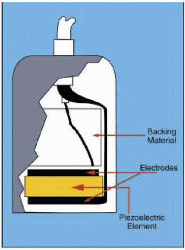 FIGURE 1.2. Piezoelectric Plate Construction. An electrical charge results when a cut plate of quartz crystal is subjected to ultrasonic mechanical stress. Conversely, the piezoelectric plate vibrates, producing ultrasonic sound waves, when it is subjected to an alternating electrical current. |
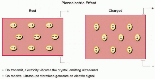 FIGURE 1.3. Piezoelectric Effect. For certain crystals and ceramics, highly polarized molecules can be made to vibrate in the presence of an electrical signal, producing an ultrasonic wave. Similarly, when such a crystal is hit by ultrasound, the vibrating molecules will generate an electrical signal at the same frequency. |
Ultrasound is generated by the piezoelectric effect. For certain types of crystals and ceramics, the molecules within the material are highly polarized, demonstrated by the ovals labeled positive and negative. When an electric charge is placed across the crystal, these dipoles attempt to line up with the electric field and their movement distorts the crystal slightly, causing it to vibrate. This vibration is transmitted into the body in the form of ultrasonic waves. The ultrasound transducer also serves as a receiver, in that reflected ultrasonic waves impacting on the crystal face cause minuscule movements of these individual dipoles, inducing an electric field that can be detected by electrodes and then amplified for processing and display in the ultrasound machine.
IMAGING WITH ULTRASOUND
All ultrasonic imaging is based on a predictable relationship between time and distance for ultrasound propagation within the body (Fig. 1.4). When an ultrasound pulse is generated, it travels at approximately 1,540 m/sec. This pulse will travel 20 cm to the object and its echo will travel 20 cm back to the ultrasound transducer. The total distance is 40 cm. The time required is approximately 267 µsec. Now if an ultrasound pulse is sent out and you know the time echo pulse returns, it is easy to calculate the distance the object is from the ultrasound transmitter. The ultrasound machine then translates this echo time interval into a distance for display on the screen. If the echo return time is t msec, then the depth (in cm) of a returning echo will be given approximately by d = 77t (5,6,7). An important limitation of ultrasound is that for unambiguous visualization of structures, a second ultrasound pulse cannot
be emitted until echoes have returned from the deepest structures of interest. This pulsed repetition frequency (PRF, in kHz) is therefore given approximately by 77/d.
be emitted until echoes have returned from the deepest structures of interest. This pulsed repetition frequency (PRF, in kHz) is therefore given approximately by 77/d.
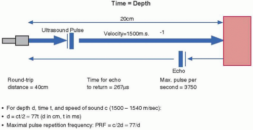 FIGURE 1.4. Imaging with Ultrasound. Because of the fairly constant speed of ultrasound in tissue (1,500-1,540 m/sec), the delay between transmission and receipt of an echo indicates the depth of the structure causing the echo. For an echo delay for t msec, the depth of centimeters is given by 77t; similarly, the maximal pulse repetition frequency (in kHz) available at depth d is given by 77/d. |
The interaction of the ultrasonic wave with the tissues and organs of the body can be described in terms of reflection, scattering, refraction, and attenuation. Reflection is the basis of all ultrasonic imaging and is where the beam is reflected at tissue boundaries and interfaces. The amount of the beam reflected is dependent on the relative change in acoustic impedance between the two tissues. Smooth tissue boundaries with lateral dimensions greater than one wavelength of the beam act as specular (mirrorlike) reflectors. Optimum return of the reflected ultrasound beam occurs at a perpendicular angle to the transducer. With less than or greater than a 90-degree angle, dropout (this appears as a poor echo image) may occur. Scattering occurs when the ultrasound beam strikes small structures (less than 1 wavelength) and the ultrasonic energy is scattered in all directions. Refraction is where ultrasound waves are deflected from a straight path as they pass through a medium with different acoustic impedance. Refraction allows enhanced image quality by using acoustic “lenses” to focus the beam, but can lead to problems, such as the “double image” artifact. Attenuation is defined as the ultrasound beam penetrates the body; the signal strength is decreased or attenuated due to absorption of the ultrasound energy by conversion to heat, as well as by reflection and scattering. Overall attenuation is frequency dependent; as you increase the frequency, the attenuation increases and the depth for adequate imaging decreases. Air has a high acoustic impedance and markedly attenuates the ultrasound signal.
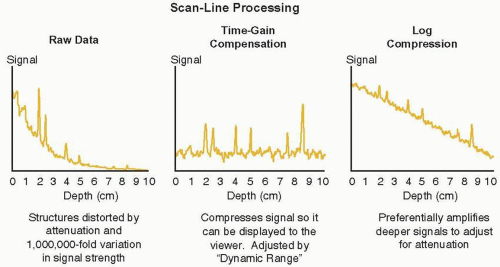 FIGURE 1.5. Scan Line Processing. Because the exponential attenuation in signal strength varies up to a millionfold with imaging depth, it is necessary to logarithmically compress the signal to make its decay linear. Differential amplification is then applied based on depth (time-gained compensation) to flatten out the back-ground signal and allow the true ultrasound reflections to emerge. |
It is important to realize that as ultrasound propagates through the body, it is continuously attenuated and dispersed as it passes through blood and tissue, especially lung tissue. The signals returning to the transducer may vary in strength by as much as a millionfold, a variation that would overwhelm the display possibilities of the machine and the interpretive abilities of the viewer. Therefore, this raw data is logarithmically compressed to turn this exponential decay in signal strength into a linear decrease in signal strength as shown in Figure 1.5.
This adjustment is termed compression and is altered by a knob on the ultrasound machine labeled either compression or dynamic range. This compressed signal still requires differential amplification so that deeper signals are brought up to the same level as more shallow echoes. This time gain compensation is typically adjusted by a series of slide controls on the machine to differentially amplify various depths of the image. By flattening out the background signal in this way, the true returning echoes can be seen with their actual echocardiographic reflectance.
This adjustment is termed compression and is altered by a knob on the ultrasound machine labeled either compression or dynamic range. This compressed signal still requires differential amplification so that deeper signals are brought up to the same level as more shallow echoes. This time gain compensation is typically adjusted by a series of slide controls on the machine to differentially amplify various depths of the image. By flattening out the background signal in this way, the true returning echoes can be seen with their actual echocardiographic reflectance.
TRANSDUCERS
The transducer is made up of the piezoelectric element, electrodes (matching layer, faceplate, and acoustic lens), case with insulation, and backing material.
Ultrasound transducers utilize piezoelectric crystals to generate and receive ultrasound waves (Fig. 1.3). These crystals have the ability to expand and compress when an electrical current is administered. Conversely, when a piezoelectric crystal receives an ultrasound wave, a high frequency electrical current is generated. Even though the crystal may function as both a transducer and receiver of ultrasound, it is referred to as a transducer even though it is in the receiver mode approximately 99% of the time (3,4,5). Currently available transducers are quite sensitive and can detect a received wavelength signal that is less than 1% of the initially transduced signal (7,8). Knowing the velocity of ultrasound in tissue and the time between the ultrasound transmission and reception, the image distance from the transducer is determined.
The transducer contains the electrodes that, when an electric current is applied to them, stimulate the piezoelectric element. These same electrodes conduct an electric current from the piezoelectric element when the reflected ultrasound beam strikes the piezoelectric element. This current travels to the ultrasound system for further processing and image production.
The matching layer or faceplate is the interface with the piezoelectric element and the esophagus in the case of transesophageal echocardiography. This layer has an acoustic impedance between the piezoelectric element and the esophagus that causes less ultrasound energy to be reflected from the esophagus and more of the ultrasound wave to be transmitted. This is further enhanced by the use of ultrasound gel between this matching layer and the esophagus. The matching layer also contains an acoustic lens to help focus the ultrasound beam. The case and insulator surround the transducer as a plastic or metal housing that functions as protection from electric noise and prevents electrical shock to the patient. The backing material or damping element acts to dampen or “ring down” the piezoelectric crystals quickly. It shortens the pulse duration and spatial pulse length. The damping material improves the picture quality. Continuous wave Doppler uses a pair of piezoelectric crystals, one continuously in the transducer mode and one in the receiver mode. Pulse wave Doppler employs a single crystal that transmits and waits to receive the return signal before transmitting again.
WAVE FRONT CHARACTERISTICS
The signal formed by multiple piezoelectric crystals is referred to as a beam and may be either unfocused or focused (Fig. 1.6). The unfocused beam travels initially in a columnar fashion in its near field zone, then spreads out in the far field. The near field’s length is directly proportional to the diameter of the transducer and inversely related to the wavelength. This is represented by this equation:
Fn = D2 / 4λ
Fn = length of the near field
D = diameter of the transducer
λ = wavelength
This near field is also called the Fresnel zone (Fig. 1.6). Images obtained in the near field are superior to the far field in image resolution (remember the inverse relationship between λ and f), and beam manipulation is better.
Fn = D2 / 4λ
Fn = D2 / 4λ = 25mm2 / 4 × 0.3mm = 20.8 cm
Distal to the near field, the beam diverges in a manner that is directly proportional to the wavelength and inversely related to the transducer diameter (divergence angle = 1.22 λ / D) (3,4,7). This is the far field, also called the Fraunholfer zone. The resulting beam has both a lateral width and height. The dispersion of the beam beyond the near field results in “side lobes,” with reflected signals being interpreted as originating from within the main beam.
Beams can be focused by either making the transducer surface concave or electronically focusing the beam by the crystal activation sequence. Focusing allows for better image resolution at the focused area, but the far field diverges greatly. Thus, images from the far field are poor in quality. The focal zone can be manipulated on the echocardiography machines to improve image resolution (Fig. 1.6).
The ability to distinguish two points in space is referred to as resolution. Such distinction may be either in the axial dimension (oriented along the length of the ultrasound beam), lateral (side-to-side resolution), or elevational
(resolution along the beam thickness). Of the three different types of resolution, axial is the most precise. Lateral resolution is dependent on the width of the generated beam. The narrow beams have better lateral resolution. Far distances from the transducer lead to a wider beam width. This wider beam width decreases the lateral resolution. Thus, there will be image blurring at greater depths of field.
(resolution along the beam thickness). Of the three different types of resolution, axial is the most precise. Lateral resolution is dependent on the width of the generated beam. The narrow beams have better lateral resolution. Far distances from the transducer lead to a wider beam width. This wider beam width decreases the lateral resolution. Thus, there will be image blurring at greater depths of field.
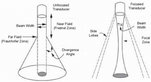 FIGURE 1.6. Unfocused versus Focused Beam. The unfocused transducer beam travels columnar in the near field (Fresnel) zone and spreads out in the far field (Fraunhofer) zone. Near field length is directly proportional to the diameter of the transducer and inversely related to the wavelength (Fn = D2 / 4λ). The far field transducer beam diverges in a manner proportional to the wavelength and inversely related to the transducer diameter (divergence angle (λ) = 1.22 λ / D). Focused beams are made by either electronic activation sequencing or physically by transducer surface concavity focusing. Focusing allows for better near field image resolution. The focal zone may be altered to improve image resolution. |
REVIEW OF CONCEPTS
Ultrasonic waves propagate through the body as longitudinal traveling waves, displacing the tissue to and from by microscopic amounts in the direction parallel to the sound production, and alternately compressing and expanding the tissue as it passes. Wave energy exists as kinetic energy in the form of particle motion and potential energy in the form of tissue compression and rarefaction. Typical ultrasound waves used in medical imaging have frequencies between 1.5 and 15 MHz. The velocity of propagation of these waves is specific to the tissue in which the waves are traveling, but for typical soft tissue, this speed is approximately 1540 m/sec. All waves are characterized by an inverse relationship between wavelength (λ) and frequency (f), with wavelength (λ) × frequency (f) = speed of propagation (c).
λ × f = 1.54 m/sec
λ = 1.54 / f
Remember the inverse relationship between wavelength and frequency. Therefore, a 1.5 MHz frequency transducer wave will have approximately a 1 mm wavelength, whereas a 15 MHz frequency transducer will have a wavelength of 0.1 mm. The image resolution can be no more than 1 or 2 wavelengths; therefore, the greater the frequency the better the resolution. The depth that the ultrasound wave will penetrate is dependent on the wavelength. The longer wavelength will have the greater penetration. There is a trade off in selecting transducer frequency—penetration versus resolution. A high frequency transducer will provide better resolution close to the probe. A lower frequency transducer will provide better penetration.
The size of the ultrasonic wave is clearly critical to determining the axial resolution of the image. To take maximal advantage of this potential resolution, an imaging ultrasound pulse must be extremely short—just one or two wavelengths in duration—whereas a Doppler ultrasound pulse, where frequency fidelity is more important, is typically longer in duration.
Resolution
Axial resolution is the ability to distinguish two structures that are close to each other and front to back. It is often called longitudinal, radial, range, or depth resolution. It is dependent on transducer frequency (higher frequency more resolution), transducer bandwidth (wider bandwidth improves resolution by allowing a shorter
pulse—less overlap of reflected signals from adjacent reflectors), and short pulse duration/length.
pulse—less overlap of reflected signals from adjacent reflectors), and short pulse duration/length.
Lateral resolution is the minimal distance two side-by-side structures can be separated and still produce two distinct echoes. It is approximately equal to beam diameter, since beam diameter varies with depth (think of near field, focus, and far field) the lateral resolution will vary with depth. Lateral resolution is the best at the focus, because the beam is the narrowest here.
Temporal resolution is resolution pertaining to time. It is the ability to accurately locate moving structures at a particular instant in time. The higher the frame rate (images per unit of time) the better the temporal resolution. The factors that affect temporal resolution (for color Doppler) include the number of pulses per scan line, the imaging depth, the sector size, and the line density (lines per angle of sector). Remember, anything that requires more time will decrease the temporal resolution.
ULTRASOUND INSTRUMENTS AND IMAGING MODALITIES
A-, B-, or M-mode Echocardiography
Cardiac ultrasound imaging modalities may be thought of in terms of one-dimensional (A-, B-, or M-mode) or two-dimensional echocardiography. More recently, three-dimensional echo has been introduced into the clinical setting. Single-dimension echo A- or B-mode echocardiography has the capability to determine the distance between the transducer and the reflective interface and the intensity of the reflected ultrasound. In the A-mode, this intensity is noted by the height of the electric signal on the oscilloscope, whereas the B-mode (brightness) echo depicts the intensity of reflection by varying degrees of brightness of the reflected point. M-mode echo provides a time or motion mode so that the B-mode is provided with a time reference (Fig. 1.7). In the B- or M-modes, only a single crystal is used. The depth of imaging is determined by only the time it takes for the ultrasound to travel from the transducer to the object and back to the ultrasound crystal. The frequency with which a transmission may be repeated is referred to as the pulse repetition frequency (PRF). The typical M-mode pulse generation frequency is up to 3,800 times per second (pulse repetition frequency) (7,8,9). Such a pulse repetition frequency permits the evaluation of rapidly moving structures, such as valve leaflets or small vegetations, on cardiac structures. This allows for superior temporal resolution.
Stay updated, free articles. Join our Telegram channel

Full access? Get Clinical Tree


