Physics and Instrumentation
Echocardiography uses ultrasound to examine the structure and function of the heart. A firm understanding of the physics of ultrasound gives the sonographer:
an understanding of the capabilities and limitations of their echo machine
the confidence to adjust the machine’s controls to optimize the images.
ELEMENTARY PHYSICS
Sound travels as a longitudinal mechanical wave, and can be thought of as a series of vibrating particles in a line. Unlike electromagnetic waves (e.g. light waves, radio waves), sound waves need the presence of particles to be transmitted – sound cannot travel though a vacuum but instead requires a medium such as air, water or a solid. When a sound wave travels through a medium, there are areas of compression (high pressure and density, where the particles are closer together) and rarefaction (low pressure and density, where they are further apart). Sound can be represented as a sine wave, showing the variation in pressure through the medium (Fig. 3.1).
The amplitude of a sound wave indicates its strength, measured as the difference between the peak pressure in the medium and the average pressure. The unit of measurement is decibels (dB), using a logarithmic scale such that a difference of 6 dB represents a doubling in amplitude. Amplitude can be adjusted by the sonographer by changing the echo machine’s power output (transmit power).
The wavelength of a sound wave is the distance between two successive waves – we normally measure this between the peak (or trough) of one wave and the identical point on the next wave. Wavelength is measured in appropriate units of length, such as metres (m) or millimetres (mm).
The frequency of a sound wave is the number of wave cycles (or oscillations) per second, and this is measured in Hertz (Hz). A sound wave with 100 oscillations per second has a frequency of 100 Hz. For high frequencies, the units of kiloHertz (kHz = 103 Hz) or MegaHertz (MHz = 106 Hz) can be used.
Audible sound lies in the frequency range 20 Hz to 20 000 Hz (20 kHz). Sound with a frequency below 20 Hz is called infrasound, and sound with a frequency greater than 20 kHz is called ultrasound. Ultrasound used for echocardiography usually lies in the frequency range 1.5-7 MHz.
The propagation velocity of a sound wave refers to the speed at which the wave propagates through the medium. This varies from one medium to another, depending both on the density and the stiffness of the medium. Propagation velocities for different body tissues are listed in Table 3.1. The average propagation velocity for the heart (and for soft tissues in general) is 1540 m/s.
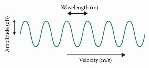 Figure 3.1 An ultrasound wave |
Table 3.1 Propagation velocities in various body tissues | ||||||||||||||
|---|---|---|---|---|---|---|---|---|---|---|---|---|---|---|
|
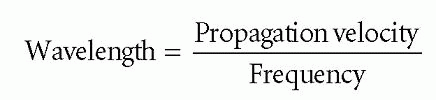
Wavelength, frequency and velocity are linked by the following equation:
Propagation velocity = frequency × wavelength
For the heart, the propagation velocity of sound waves is fixed at approximately 1540 m/s – this cannot be altered by the sonographer. The sonographer can, however, choose the frequency of the sound waves being transmitted towards the heart. Choosing different frequencies will therefore influence the wavelength of the sound waves as they are transmitted through the heart (and the surrounding tissues). If, for instance, the sonographer was to choose a frequency of just 5 kHz, then the wavelength of the sound waves would be:
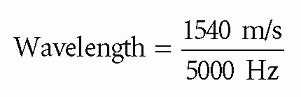
Wavelength = 0.308 m
Such a long wavelength, of just over 30 cm, would give very little spatial resolution and would be of little use for cardiac imaging. The higher the frequency chosen, the shorter the wavelength. As shorter wavelengths provide better resolution (see later), higher frequencies of between 1.5 MHz and 7 MHz are used for echo imaging.
So why not use even higher frequencies and get even better image resolution? One reason is that there is a trade-off between resolution and penetration – the higher the ultrasound frequency, the better the resolution but the poorer the penetration of the ultrasound into the body. The ultrasound frequencies used for echo offer a good balance between resolution and penetration. Paediatric echo uses higher frequencies (typically 5-10 MHz) than adult echo, as the patient’s smaller body size means that less penetration is required. Similarly, in intravascular ultrasound (p. 107), where high resolution but little penetration is required, frequencies of 20-50 MHz are used.
ULTRASOUND PROPAGATION
As an ultrasound pulse is transmitted from a transducer and into the body, it will encounter a number of different tissues, each of which has a different acoustic impedance (‘resistance’ to ultrasound transmission). These differences in acoustic impedance are particularly important at the boundaries between tissues. When an ultrasound pulse crosses a boundary between two tissues with very different acoustic impedances, a large proportion of the energy within the pulse will be reflected back towards the transducer.
This effect is most marked at the boundary between the air and the skin, where almost all of the ultrasound energy will be reflected back to the transducer and less than 1 per cent will enter the body. This would be a major drawback to performing medical ultrasound, so to get around this problem sonographers use gel to bridge the gap between the transducer and the skin. By excluding the air between the transducer and the skin, the gel reduces the impedance mismatch and allows much more of the ultrasound energy to enter the body. Similarly, echo can be challenging in patients with hyperinflated lungs (e.g. emphysema), where views of the heart can be obscured by air-filled lung tissue causing a large impedance mismatch.
As the ultrasound pulse is transmitted through the body, it will meet further boundaries where different degrees of reflection occur. There are two types of reflection (Fig. 3.2):
specular reflection
backscatter.
Specular (‘mirror-like’) reflection occurs at tissue boundaries where the reflector is relatively large (at least two wavelengths in diameter) and smooth – structures such as the heart valves and the walls of the heart chambers and major vessels are examples of specular reflectors. The proportion of ultrasound energy reflected by a specular reflector is highly dependent on the angle of incidence of the incoming ultrasound beam – in order to maximize the amount of energy reflected, the incoming beam should be as perpendicular (i.e. as close to 90°) to the reflector as possible.
Backscatter occurs with small and/or rough-surfaced structures, where the reflected ultrasound will scatter in many different directions. The returning signal will be weaker than from a specular reflector, but will not be dependent on the angle of the incident (incoming) ultrasound beam. An example of a scatter reflector is the tissue within the myocardium. Red blood cells also cause scatter, and as this scatter
is equal in all directions they are referred to as a special group known as Rayleigh scatterers.
is equal in all directions they are referred to as a special group known as Rayleigh scatterers.
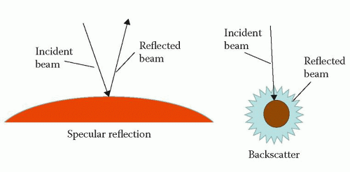 Figure 3.2 Specular reflection and backscatter |
As an ultrasound pulse travels through tissue, it will gradually lose energy, a process known as attenuation. Attenuation results from reflection and backscatter, and also from the absorption of energy by the tissues themselves (where the sound energy is converted into heat). This loss of energy can be quantified in decibels, and in soft tissues a change of -3 dB equates to a fall in signal intensity of 50 per cent. The half-intensity depth (HID) is the depth (in cm) in soft tissue in which the intensity of the ultrasound is reduced by 50 per cent, and depends upon the frequency (f) of the ultrasound emitted by the transducer, measured in MHz:
Thus the ultrasound emitted by a 4 MHz transducer would lose 50 per cent of its intensity after travelling through just 6/4 = 1.5 cm of soft tissue. Attenuation is therefore greater at higher frequencies.
Refraction is the change in direction of an ultrasound pulse as it passes across a boundary between two tissues (or materials) of different acoustic impedance. Although refraction can be useful (for instance, refraction is used to focus the ultrasound beam with an acoustic lens), it can also be a source of artefact (p. 21).
ULTRASOUND TRANSDUCERS
In transthoracic echo, ultrasound is generated by a transducer (commonly called a probe) which is held on the patient’s chest. For other imaging techniques (e.g. transoesophageal echo (TOE), intravascular ultrasound), the transducer may be passed into the oesophagus or even into the heart itself. The transducer is both a transmitter and a receiver – it transmits ultrasound into the chest, and also detects the return of the reflected ultrasound back to the probe.
Ultrasound transducers work using the piezoelectric effect. Piezoelectric crystals change shape when an electrical voltage is applied, and so an alternating voltage can make them oscillate rapidly, thereby generating ultrasound. In addition, if the crystals are themselves caused to oscillate by a returning ultrasound wave, they generate an electrical voltage which can be detected as a signal. Thus the crystals both generate and detect ultrasound.
Contemporary phased-array transducers consist of an array of piezoelectric elements (typically 128 for a 2D echo probe, several thousand for a 3D


Stay updated, free articles. Join our Telegram channel
Full access? Get Clinical Tree
