16 Percutaneous Mitral Commissurotomy and Balloon Aortic Valvuloplasty
Percutaneous Mitral Commissurotomy
Inoue reported a single balloon technique for mitral commissurotomy in 1984. Although a number of other techniques have subsequently been described, the Inoue balloon technique and the double balloon technique have been used most commonly. The Inoue technique is the most frequently used in practice internationally and is at present the only approved mitral dilatation balloon in the United States.
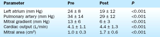
Hemodynamic results have been well characterized by the Inoue Multi-Center Registry. On average there is more than 80% increase in mitral valve area. Balloon inflation results in splitting of the fused commissures with reductions in the transmitral pressure gradient, the mean left atrial pressure, and the pulmonary artery pressure. The cardiac output and mitral valve area increase (Table 16-1).
The most important complication of the procedure is mitral regurgitation. Mitral valve replacement is needed during the initial hospitalization in about 2% of patients. An additional 3% to 4% have resultant 3+ or greater mitral regurgitation without the need for immediate valve replacement. Other complications are shown in Table 16-2.
Table 16-2 Complications of Percutaneous Transvenous Mitral Commissurotomy
Complication | % |
---|---|
Hospital mitral valve replacement (MVR) | 1.0 |
Hospital death | 1.4 |
Transient ischemic attack | 0.6 |
Stroke | 0 |
Cardiac perforation | 1.4 |
Pericardiocentesis | 1.0 |
Myocardial infarction | 0.3 |
Cardioversion shock for atrial or ventricular fibrillation | <1 |
Vascular repair | 0.6 |
Transfusion | 0.3 |
Temporary pacer | 0 |
Mitral regurgitation 3+ or more (no MVR) | 3.8 |
Atrial septal defect >1.5 | 3.1 |
Failure to cross mitral valve | 1.7 |
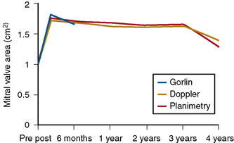
The durability of the results is excellent. Figure 16-1 shows the stability of the achieved valve area over a period of years. The 5-year actuarial freedom from death with mitral valve replacement or repeat balloon commissurotomy for the Inoue Registry population was 71%. More than 80% of the patients remained symptomatically improved at 5 years.

Figure 16-1 Mitral valve area before percutaneous transvenous mitral commissurotomy (PTMC), immediately after and 4 years following PTMC. Gorlin-calculated valve areas were obtained in 86 patients at repeat catheterization. Doppler and planimetry areas remained relatively constant for 3 years and then fell off slightly in the fourth year.
Technique
The Inoue Balloon
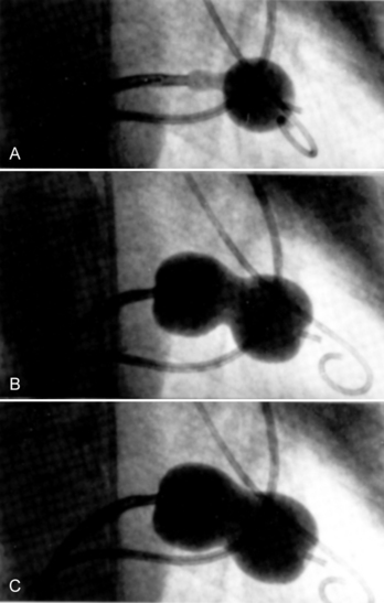
The Inoue device differs substantially from conventional balloons. It is constructed of two layers of latex with a nylon mesh sandwiched in between them. The latex is compliant, whereas the nylon mesh limits the maximum inflated diameter of the balloon and gives it a unique shape and three-stage inflation characteristics (Fig. 16-2).

Figure 16-2 A, Front half of balloon inflated and passed across the mitral valve orifice. This is analogous to the manner in which a balloon flotation catheter is maneuvered from the right atrium to the right ventricle during right heart catheterization. The partially inflated balloon is pulled back until it engages the mitral valve. B, Front and back portions of balloon inflated, creating a “dog-bone” shape that self-positions the balloon in the mitral orifice. C, Almost fully inflated balloon opening the commissures. Note that the inferior indentation in the balloon is more pronounced than the superior indentation, signifying incomplete commissural separation.
The front half of the balloon inflates first, giving the appearance of a balloon flotation catheter. The proximal half of the balloon inflates next, creating a dumbbell or hourglass shape. When it is passed across the mitral valve, this shape facilitates self-positioning of the balloon device in the valve orifice. Finally, the center portion of the balloon inflates, resulting in splitting of the fused mitral valve leaflet commissures. The distensibility of the latex material allows each balloon to be inflated over a 4-mm range of diameter sizes (i.e., between 26 and 30 mm diameter for the largest available model). A single balloon can thus be used to cause sequential dilatation of the valve by inflating it to serially larger diameters without removing it from the patient. This procedure is thus analogous to coronary angioplasty, during which the result of the balloon inflations is evaluated and additional balloon inflations are performed if necessary.
Patient Evaluation
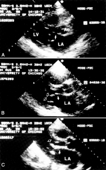
Evaluation by two-dimensional transthoracic and transesophageal echocardiography is essential before mitral valvotomy. Patients with thin, pliable mitral leaflets and minimally diseased subvalvular apparatus have the best long-term outcome from surgical commissurotomy (Fig. 16-3). This is no less true when using percutaneous methods to achieve commissurotomy. Although the immediate results of percutaneous transvenous mitral commissurotomy (PTMC) are acceptable in patients with significant valve deformity, the restenosis rate and the need for rate mitral valve replacement remains higher in these patients. The goal of therapy and the long-term prospects for event-free survival must be appropriate for patients with significant valve deformity and echocardiographic scores greater than 10 to 12.

Figure 16-3 A, Long-axis two-dimensional echocardiographic image from an ideal candidate for mitral commissurotomy. The solid arrows show the thin, domed leaflets. The mitral apparatus is not visible in the left ventricle, signifying its freedom from significant thickening. B, Typical valve replacement candidate. The solid arrow points at a thickened and calcified anterior mitral leaflet. The open arrows show the thickened submitral apparatus. These patients have echocardiographic scores between 8 and 12 and are reasonable candidates for percutaneous transvenous mitral commissurotomy, although they may have poorer long-term freedom from mitral valve replacement. C, Elderly patient, not a likely candidate for surgical therapy of any kind. This patient was an 88-year-old woman. The solid arrow shows a densely calcified, thickened, and rigid anterior mitral leaflet. The open arrow points to the similarly thickened and calcified mitral apparatus. Balloon dilatation may be accomplished successfully in these patients but with acute results that are not as good as those in patients with less deformed valves. The long-term event-free outcome for these patients is poor.
(From Feldman T, Carroll JD. Cardiac catheterization, balloon angioplasty, and percutaneous valvuloplasty. In Hall JB, Schmidt GA, Wood LDH, eds. Principles of critical care. New York: McGraw-Hill, 1992:343–360.)
Transesophageal echocardiography before PTMC is useful for the detection of atrial thrombi. Even when PTMC was performed in patients before the widespread use of transesophageal echocardiography, embolic events were infrequent. Experience since the routine use of transesophageal echo screening has virtually eliminated the chance of this devastating complication.
Atrial thrombi are a strong relative contraindication to the performance of both transseptal puncture and balloon mitral valvotomy. Atrial thrombi are found in 15% to 25% of patients with mitral stenosis being considered for PTMC, many of whom have been on long-term warfarin anticoagulation therapy even when sinus rhythm is present. In many cases when atrial thrombi are noted, it is possible to either institute or intensify anticoagulation for 3 to 12 months and achieve resolution of thrombi. PTMC may then be undertaken without unnecessary risk. In some cases, small, densely organized thrombi in the atrial appendage may be present. These thrombi are not as likely to contain fresh clots or to be mobile. It is possible to do PTMC in these cases without complications, although this must be done with extreme care and recognition of the serious risk of stroke. Operator experience with the handling characteristics of the Inoue balloon steering stylette is essential in this setting. An option for patients with atrial thrombi, when the risk of PTMC seems justified for other clinical reasons, is to cross the mitral valve with a 7F balloon-tipped catheter, pass the Inoue exchange wire through the balloon catheter into the left ventricle, and then pass the Inoue balloon over this wire. This avoids manipulation of the valvuloplasty device in the left atrium. Some patients in atrial fibrillation without prior anticoagulation therapy are found not to have atrial thrombi upon transesophageal echocardiographic examination. In these cases balloon dilatation may proceed without a prior course of anticoagulation.
Cardiac Catheterization Technique
1. The left femoral arterial and venous sheaths are placed. Because a pigtail catheter will be left in place in the left ventricle for a relatively long period of time, we prefer to use 5F or 6F arterial catheters.
2. A multilumen pulmonary artery balloon catheter with thermodilution cardiac output capability is used for right heart catheterization. Left femoral access is preferred for these catheters, leaving the right side for insertion of the dilatation balloon catheter. Pulmonary artery catheters with oximetric monitoring simplify the evaluation of venous saturations for the detection of atrial shunting following the procedure, although these catheters are more difficult to place than are conventional pulmonary artery catheters. Passage of the pulmonary artery catheter is facilitated by the use of an extra-stiff 0.025-inch guidewire.
3. Left ventriculography and coronary arteriography are performed when indicated. The AHA/ACC guidelines for valvular heart disease recommend arteriography for men over age 35 years, or women over age 35 years who also have risk factors.
4. Right heart pressures and cardiac output are measured.
5. Right femoral venous puncture is performed for placement of an 8F Mullins sheath. Placement of a 14F sheath at this stage makes passage and removal of the balloon much easier. An extra-stiff 0.035-inch wire should be used for insertion of the large venous sheath. If a 14F sheath is not used, free movement of the balloon can be impaired by binding in the subcutaneous tissues at the groin puncture site. In very heavy patients the catheter may make a severe angle between the skin and the femoral vein. An ipsilateral pulmonary artery catheter does not interfere with the performance of the transseptal catheterization.
6. Following transseptal puncture, heparin is administered. The transmitral pressure gradient is measured using the Mullins sheath for the left atrial and the pigtail for left ventricular pressures. If the Mullins sheath can be passed into the left ventricle with a gentle counterclockwise rotation, a transaortic gradient is measured with the Mullins and pigtail to exclude aortic valve disease.
A simplified procedure with no arterial access and no pulmonary artery catheterization is not recommended. The safety of the procedure and the evaluation of the resultant possible complications mandate continuous arterial pressure monitoring, a full right heart catheterization before and after the procedure, and accurate cardiac output determination.
Selection of Balloon Size
Balloon sizing has not been rigorously defined by any study; rather a combination of experience in the first decade of mitral valvotomy, common sense, and data from a few studies has established the approach to balloon sizing.
The maximum expected inflated balloon diameter may be selected based on the patient’s height (Table 16-3). This value provides a guideline for balloon selection with a stepwise technique. A first inflation is always performed at a diameter smaller than the maximum possible for the selected balloon. An initial inflation of 2 to 4 mm less than the maximum is usually chosen. An alternative method for selecting balloon size is to calculate the ratio of inflated dilating balloon area to the body surface area, called the effective balloon dilating area (EBDA).
Table 16-3 Selection of Balloon Size for Percutaneous Transvenous Mitral Commissurotomy
Balloon diameter (range, mm) | Balloon dilating area (cm2) | Patient height, cm (inches) |
---|---|---|
26 to 30 | 7.07 | >180 (70.9) |
24 to 28 | 6.16 | >160 (62.9) |
22 to 26 | 5.13 | <160 |
This method results in somewhat different values for maximal balloon size in a given patient compared to the recommendations originally made by Inoue based on his empiric observations. When the Inoue balloon is inflated to an EBDA of 4.0 using a single inflation without the stepwise technique, results similar to those reported for the stepwise technique have been achieved. EBDA may not be equally useful in all patient populations. For overweight or obese patients, in particular, a better estimate of largest expected balloon inflation balloon diameter may be based on height alone.
For patients with pliable valves, the first balloon inflation can be made with a balloon inflation 2 or 3 mm smaller than the reference size and then increased in increments of 1 mm until either a maximal diminution of gradient has occurred or mitral regurgitation has begun to worsen significantly. For patients with more deformed valves, the first inflation can be performed at 4 mm less than the reference size with increments of 1 mm in size while the balloon is in the shallow or low- pressure portion of the pressure-volume cure. Increments of 0.5 mm may then be used over the last couple of millimeters of balloon diameter when the balloon reaches the high- pressure portion of its pressure-volume curve.
Special Considerations
There are a number of special considerations in balloon size selection. Smaller balloons than initially estimated may be useful in patients with advanced age, patients with subvalvular disease, or those in whom persistence with marked constriction during full inflation indicates that balloon pressure may be insufficient. In this last situation, the use of a smaller balloon inflated to the same diameter as a previous larger balloon will result in a greater inflation pressure.
The Stepwise Technique
The stepwise balloon expansion technique obviates the need for precise determination of maximum inflated balloon diameter. Because the Inoue device may be inflated over a range of sizes, balloon size selection need only be accurate enough to address this range. Although patient and balloon characteristics may be evaluated in a consistent manner, the inhomogeneity of the valve pathology and the limitations of our ability to predict ultimately what balloon sizes and pressures will produce commissural splitting make the stepwise approach more practical than preprocedure predictions of expected balloon size.
Balloon Preparation
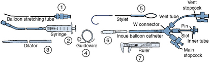
Once the diagnosis of mitral stenosis is confirmed after successful transseptal puncture, the balloon catheter can be prepared. The balloon catheter comes packaged with all the components necessary for the dilatation procedure (Fig. 16-4). These include:
• A balloon-stretching metal tube
• A calibrated inflation syringe specifically matched to each balloon
• A rigid 12F to 14F plastic dilator
• A 0.025-inch spring-tipped exchange guidewire
• A stylet for manipulating the balloon across the mitral valve after it has been placed in the left atrium
• Calipers for measuring the balloon diameter and confirming its inflated size

Figure 16-4 The components of the equipment box supplied by Toray include (1) a long metal hypotube, the balloon-stretching tube, used to pass through the inner tube of the Inoue balloon catheter to elongate and slenderize the balloon; (2) a calibrated syringe used for inflation of the balloon. The syringe provides calibration marks so that predetermined diameters of the balloon can be achieved driven by the volume rather than pressure; (3) a dilator used to dilate the subcutaneous tissue at the femoral venous puncture site and to dilate the septum as well; (4) a 0.025-inch stainless steel spring guidewire; (5) a steering stylet that is introduced through the inner tube after the balloon is in the left atrium to help guide it across the mitral valve; (6) the balloon catheter itself, which has a W connector from which arise a vent tube, an inner tube used for introduction of the balloon-stretching tube and stylet, and for stretching the balloon, and a main stopcock for balloon inflation via the syringe; (7) a ruler or caliper, which is used to confirm that the graduations on the syringe used to inflate the balloon result in the desired inflation diameters.
The balloon catheter lumen is flushed with saline. Dilute contrast (saline:contrast 2:1 or 3:1) is injected through the vent lumen to purge air from the inflate/deflate channel to the balloon and the stopcock is closed on that lumen.
The precalibrated balloon inflation syringe is filled to the calibration corresponding to the smallest inflated diameter. After connecting the inflation syringe to the inflation port and checking that all connections are secure, the balloon is slowly inflated over a period of 5 seconds so that the nylon mesh may be slowly stretched without risking mesh rupture.
The balloon is allowed to deflate passively in a bath of flush solution. Small bubbles will escape from within the mesh layer of the balloon. The balloon is then inflated rapidly and the inflated diameter is measured using calipers to verify the precalibrated inflation syringe. If the balloon does not inflate to the desired diameter, small amounts of contrast are added or subtracted to achieve proper calibration.
The syringe is then filled to the calibration corresponding to the maximum nominal inflated size. The balloon may be tested to ensure that the maximum size calibration is also correct. In practice, this calibration step is often omitted. The next step in balloon preparation is to elongate the balloon catheter along its long axis, causing it to become more slender. A metal tube (balloon-stretching tube) is inserted into the center lumen of the balloon over the guidewire and advanced until it locks into the metal hub at the proximal end of the balloon catheter. The balloon and stretching tube are then advanced into the balloon catheter shaft until they engage the plastic slot on the balloon catheter Luer lock. This leaves the balloon in its elongated, slenderized form to ease not only percutaneous insertion but also delivery across the interatrial septum.
Balloon Valvotomy
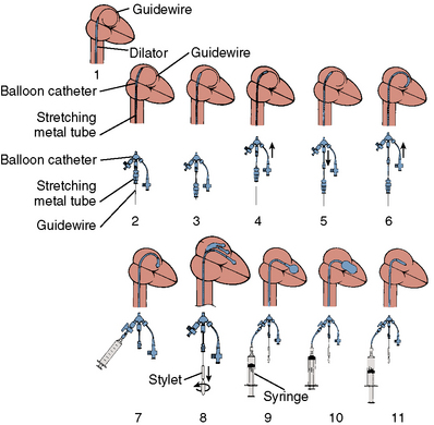
The major steps in valvotomy are illustrated diagrammatically in Figure 16-5. The 0.025-inch spring guidewire is advanced through the Mullins sheath into the left atrium with the fully coiled distal portion out of the sheath and positioned in the roof of the atrium. The Mullins sheath is withdrawn over the guidewire with the guidewire remaining in the left atrium. The dilator is advanced through the skin and then into the atrial septum, where it may be passed through the septal puncture as shown in Figure 16-5. The dilator is left sitting in the septal puncture for several seconds to stretch the septal tissue. The dilator is removed and the balloon catheter is passed over the guidewire via the 14F sheath and then across the atrial septum.

Figure 16-5 Schematic illustration of the Inoue balloon mitral valvotomy procedure. (1) After a spring guidewire is introduced via a Mullins sheath into the left atrium, the interatrial septum is dilated using a rigid 14F plastic dilator. (2) The elongated balloon catheter is advanced over the wire through the interatrial septum. (3) The stretching metal tube is partially withdrawn, allowing the balloon to shorten and curl within the left atrium. (4) The balloon is advanced through the interatrial septum. (5) The stretching metal tube and balloon straightening device are withdrawn further. (6) The balloon is advanced beyond the mitral orifice. (7) The distal portion of the balloon is partially inflated with a contrast-saline mixture. (8) With counterclockwise rotation of the stylet, slight advancement of the catheter shaft, and withdrawal of the stylet, the balloon is directed through the mitral orifice and left ventricle. (9) The partially inflated balloon is withdrawn against the mitral orifice. (10) The balloon is fully and rapidly inflated and allowed to deflate. (11) After deflation, in most instances, the balloon passively returns to the left atrium from the left ventricle.
(Courtesy of Toray, Inc., Tokyo, Japan.)
After the balloon is passed through the atrial septum, it must be allowed to resume its unstretched conformation to prevent the very stiff slenderizing tube from puncturing the roof of the left atrium. In some cases the blunt tip of the balloon will catch on the right atrial side of the septal puncture. Rotating the catheter slowly with gentle probing pressure will allow it to find its way through the septal puncture into the left atrium. Rarely, a 10- to 12-mm peripheral angioplasty balloon must be used to dilate the atrial septum. After the tip of the balloon has passed across the atrial septum, the stretching metal tube is then disengaged from the catheter metal hub and withdrawn as the balloon catheter is advanced. The tip of the balloon will then begin to track around the coiled spring guidewire. As the balloon reaches the roof of the left atrium, the gold metal Luer lock is disconnected and pulled back, allowing the balloon to shorten. The balloon catheter is then advanced further over the spring-tipped guidewire. The balloon-stretching tube and spring guidewire are removed from the patient and cleaned and prepared for later use to remove the balloon. It is important to track the balloon around over the wire until it reaches the inferior portion of the left atrium so it overlies the mitral orifice before removing the wire.
The balloon catheter can be flushed and connected to a pressure transducer. The transmitral pressure gradient can be remeasured through the balloon catheter to verify that the pressure wave form is similar to that obtained through the Mullins sheath. The wave form appears slightly damped through the lumen of the Inoue balloon.

Stay updated, free articles. Join our Telegram channel

Full access? Get Clinical Tree

