Anatomy and Physiology of the Cardiac Conduction System
The cardiac conduction system consists of specialized tissue involved in the generation and conduction of electrical impulses throughout the heart. In this book, we review how device therapy can be optimally utilized for various forms of conduction system disturbances, tachyarrhythmias, and for heart failure. Knowledge of the normal anatomy and physiology of the cardiac conduction system is critical to understanding appropriate utilization of device therapy.
The sinoatrial (SA) node, located at the junction of the right atrium and the superior vena cava, is normally the site of impulse generation (Fig. 1.1). The SA node is composed of a dense collagen matrix containing a variety of cells. The large, centrally located P cells are thought to be the origin of electrical impulses in the SA node, which is surrounded by transitional cells and fiber tracts extending through the perinodal area into the right atrium proper. The SA node is richly innervated by the autonomic nervous system, which has a key function in heart rate regulation. Specialized fibers, such as Bachmann’s bundle, conduct the impulse throughout the right and left atria. The SA node has the highest rate of spontaneous depolarization and under normal circumstances is responsible for generating most impulses. Atrial depolarization is seen as the P wave on the surface ECG (Fig. 1.1).
Fig. 1.1 (A) The cardiac conduction system. AV, atrioventricular; SA, sinoatrial. Conduction begins with impulse generation in the SA node (left panel). Impulse propagation through the atria gives rise to the P wave on the surface ECG (bottom of left panel). The impulse is then delayed in the AV node to allow blood to flow to the ventricles; wavefront travel through the AV node is not seen on the surface ECG. The wavefronts then pass through the His–Purkinje system, to rapidly activate the ventricular myocardium. The larger mass of the ventricles give rise to the large amplitude QRS complex. Further details in text. (B) An anatomic specimen showing the location of key conduction system elements. The top panel shows an external view of the heart with the region of the SA node in the epicardium at the juncture of the superior vena cava (SVC) and right atrium (RA) indicated. The structure itself is not visible to the naked eye. IVC, inferior vena cava. In the bottom panel the right atrial and ventricular free wall has been removed to reveal the position of the AV node anterior to the coronary sinus (CS) and atrial to the tricuspid valve (TV), situated in Koch’s triangle (bounded by the TV, CS, and tendon of Todaro, not shown). FO, fossa ovalis.
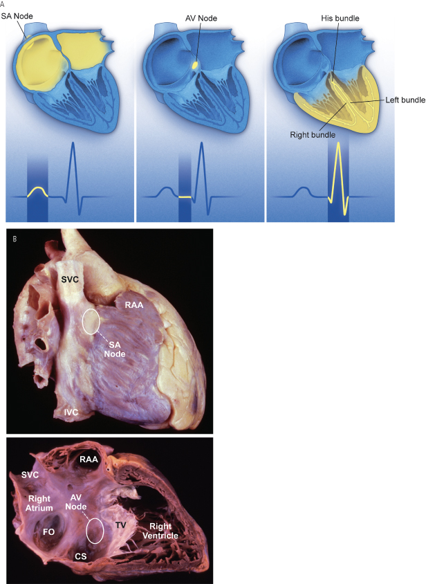
Atrial conduction fibers converge, forming multiple inputs into the atrioventricular (AV) node, a small subendocardial structure located within the interatrial septum (Fig. 1.1). The AV node likewise receives abundant autonomic innervation, and it is histologically similar to the SA node because it is composed of a loose collagen matrix in which P cells and transitional cells are located. Additionally, Purkinje cells and myocardial contractile fibers may be found. The AV node allows for physiologic delay between atrial and ventricular contraction, resulting in optimal cardiac hemodynamic function. It can also function as a subsidiary “pacemaker” should the SA node fail. Finally, the AV node functions (albeit typically suboptimally) to regulate the number of impulses eventually reaching the ventricle in instances of atrial tachyarrhythmia. On the surface ECG, the majority of the PR interval is represented by propagation through the AV node and through the His–Purkinje fibers (Fig. 1.1).
Purkinje fibers emerge from the distal AV node to form the bundle of His, which runs through the membranous septum to the crest of the muscular septum, where it divides into the various bundle branches. The bundle branch system exhibits significant individual variation and is invariably complex. The right bundle is typically a discrete structure running along the right side of the interventricular septum to the anterior papillary muscle, where it divides. The left bundle is usually a large band of fibers fanning out over the left ventricle, sometimes forming functional fascicles. Both bundles eventually terminate in individual Purkinje fibers interdigitating with myocardial contractile fibers. The His–Purkinje system has little in the way of autonomic innervation.
Because of their key function and location, the SA and AV nodes are the most common sites of conduction system failure; it is therefore understandable that the most common indications for pacemaker implantation are SA node dysfunction and high-grade AV block. It should be noted, however, that conduction system disease is frequently diffuse and may involve the specialized conduction system at multiple sites.
Electrophysiology of Myocardial Stimulation
Stimulation of the myocardium requires the initiation of a propagating wave of depolarization from the site of initial activation, whether from a native “pacemaker” or from an artificial stimulus. Myocardium exhibits “excitability,” which is a response to a stimulus out of proportion to the strength of that stimulus.1 Excitability is maintained by separation of chemical charge, which results in an electrical transmembrane potential. In cardiac myocytes, this electrochemical gradient is created by differing intracellular and extracellular concentrations of sodium (Na+) and potassium (K+) ions; Na+ ions predominate extracellularly and K+ ions predominate intracellularly. Although this transmembrane gradient is maintained by the high chemical resistance intrinsic to the lipid bilayer of the cellular membrane, passive leakage of these ions occurs across the cellular membrane through ion channels. Passive leakage is offset by two active transport mechanisms, each transporting three positive charges out of the myocyte in exchange for two positive charges that are moved into the myocyte, producing cellular polarization.2,3 These active transport mechanisms require energy and are susceptible to disruption when energy-generating processes are interrupted.
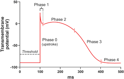
The chemical gradient has a key role in the generation of the transmembrane action potential (Fig. 1.2). The membrane potential of approximately −90 mV drifts upward to the threshold potential of approximately −70 to −60 mV. At this point, specialized membrane-bound channels modify their conformation from an inactive to an active state, which allows the abrupt influx of extracellular Na+ ions into the myocyte,4,5 creating phase 0 of the action potential and rapidly raising the transmembrane potential to approximately +20 mV.6,7 This rapid upstroke creates a short period of overshoot potential (phase 1), which is followed by a plateau period (phase 2) created by the inward calcium (Ca2+) and Na+ currents balanced against outward K+ currents.8–10 During phase 3 of the action potential, the transmembrane potential returns to normal, and during phase 4 the gradual upward drift in transmembrane potential repeats. The shape of the transmembrane potential and the relative distribution of the various membrane-bound ion channels differ between the components of the specialized cardiac conduction system and working myocytes.
Fig. 1.2 Action potential of a typical Purkinje fiber, with the various phases of depolarization and repolarization (described in the text).
(From Stokes KB, Kay GN. Artificial electric cardiac stimulation. In: Ellenbogen KA, Kay GN, Wilkoff BL, eds. Clinical Cardiac Pacing. Philadelphia: WB Saunders Co., 1995: 3–37, by permission of the publisher.)
Depolarization of neighboring cells occurs as a result of passive conduction via low-resistance intercellular connections called “gap junctions,” with active regeneration along cellular membranes.11,12 The velocity of depolarization throughout the myocardium depends on the speed of depolarization of the various cellular components of the myocardium and on the geometric arrangement and orientation of the myocytes. Factors such as myocardial ischemia, electrolyte imbalance, metabolic abnormalities, myocardial scar, diseased tissue, and drugs affect the depolarization and depolarization velocity.
Pacing Basics
Stimulation Threshold
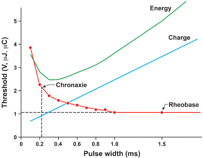
Artificial pacing involves delivery of an electrical impulse from an electrode of sufficient strength to cause depolarization of the myocardium in contact with that electrode and propagation of that depolarization to the rest of the myocardium. The minimal amount of energy required to produce this depolarization is called the stimulation threshold. The components of the stimulus include the pulse amplitude (measured in volts) and the pulse duration (measured in milliseconds). An exponential relationship exists between the stimulus amplitude and the duration, resulting in a hyperbolic strength–duration curve. At short pulse durations, a small change in the pulse duration is associated with a significant change in the pulse amplitude required to achieve myocardial depolarization; conversely, at long pulse durations, a small change in pulse duration has relatively little effect on threshold amplitude (Fig. 1.3). Two points on the strength–duration curve should be noted (Fig. 1.4). The rheobase is defined as the smallest amplitude (voltage) that stimulates the myocardium at an infinitely long pulse duration (milliseconds). The chronaxie is the threshold pulse duration at twice the rheobase voltage. The chronaxie is important in the clinical practice of pacing because it approximates the point of minimum threshold energy (microjoules) required for myocardial depolarization.
Fig. 1.3 Relationship of charge, energy, voltage, and current to pulse duration at stimulation threshold. As the pulse duration is shortened, voltage and current requirements increase. Charge decreases as pulse duration shortens. At threshold, energy is lowest at a pulse duration of 0.5–1.0 ms and increases at pulse widths of shorter and longer duration.
(Modified from Furman S. Basic concepts. In: Furman S, Hayes DL, Holmes DR Jr, eds. A Practice of Cardiac Pacing. Mount Kisco, NY: Futura Publishing Co., by permission of the publisher.)
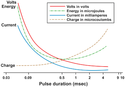
Fig. 1.4 Relationships among chronic ventricular strength–duration curves from a canine, expressed as potential (V), charge (μC), and energy (µJ). Rheobase is the threshold at infinitely long pulse duration. Chronaxie is the pulse duration at twice rheobase.
(From Stokes K, Bornzin G. The electrode–biointerface stimulation. In: Barold SS, ed. Modern Cardiac Pacing. Mount Kisco, NY: Futura Publishing Co., 1985: 33–77, by permission of the publisher.)
The relationship of voltage, current, and pulse duration to stimulus energy is described by the formula

in which E is the stimulus energy, V is the voltage, R is the total pacing impedance, and t is the pulse duration. This formula demonstrates the relative increase in energy with longer pulse durations. The energy increase due to duration is offset by a decrement in the needed voltage. The strength–duration curve discussed thus far has been that of a constant voltage system, which is used in all current pacemakers and defibrillators. Constant current devices are no longer used.
Impedance is the term applied to the resistance to current flow in the pacing system. Ohm’s law describes the relationship among voltage, current, and resistance as

in which V is the voltage, I is the current, and R is the resistance. Although Ohm’s law is used for determining impedance, technically impedance and resistance are not interchangeable terms. Impedance implies inclusion of all factors that contribute to current flow impediment, including lead conductor resistance, electrode resistance, resistance due to electrode polarization, capacitance, and inductance. Technically, the term “resistance” does not include the effects of capacitance (storage of charge) or inductance (storage of current flow) to impede current flow. Nevertheless, Ohm’s law (substituting impedance for R) is commonly used for calculating impedance. In constant voltage systems, the lower the pacing impedance, the greater the current flow; conversely, the higher the pacing impedance, the lower the current flow. Lead conductors are designed to have a low resistance to minimize the generation of energy-wasting heat as current flows along the lead, and electrodes are designed to have a high resistance to minimize current flow and to have negligible electrode polarization. Decreasing the electrode radius minimizes current flow by providing greater electrode resistance and increased current density, resulting in greater battery longevity and lower stimulation thresholds.13
“Polarization” refers to layers of oppositely charged ions that surround the electrode during the pulse stimulus. It is related to the movement of positively charged ions (Na+ and H3O+) to the cathode; the layer of positively charged ions is then surrounded by a layer of negatively charged ions (Cl−, HPO42−, and OH−). These layers of charge develop during the pulse stimulus, reaching peak formation at the termination of the pulse stimulus, after which they gradually dissipate. Polarization impedes the movement of charge from the electrode to the myocardium, resulting in a need for increased voltage for stimulation. As polarization develops with increasing pulse duration, one way to combat formation of polarization is to shorten the pulse duration. Electrode design has incorporated the use of materials that minimize polarization, such as platinum black, iridium oxide, titanium nitride, and activated carbon.14 Finally, polarization is inversely related to the surface area of the electrode. To maximize the surface area (to reduce polarization) but minimize the radius (to increase electrode impedance), electrode design incorporates a small radius but a porous, irregular surface construction.15 Fractal coatings on the lead tip increase the surface area 1000-fold without the need to increase the axial diameter. Leads designed to maximize these principles are considered “high-impedance” leads.
Variations in Stimulation Threshold
Myocardial thresholds typically fluctuate, occasionally dramatically, during the first weeks after implantation. After implantation of earlier generations of endocardial leads, the stimulation threshold would typically rise rapidly in the first 24 h and then gradually increase to a peak at approximately 1 week (Fig. 1.5). Over the ensuing 6–8 weeks, the stimulation threshold would usually decline to a level somewhat higher than that at implantation, but less than the peak threshold, known as the “chronic threshold.”16,17 The magnitude and duration of this early increase in threshold was highly dependent on lead design, the interface between the electrode and the myocardium, and individual patient variation, but chronic thresholds would typically be reached by 3 months. The single most important lead design change to alter pacing threshold evolution was the incorporation of steroid elution at the lead tip, to blunt the local inflammatory response (Fig. 1.6). With steroid elution there may be a slight increase in thresholds post-implantation, with subsequent reduction to almost that of acute thresholds.18,19
Fig. 1.5 Long-term pacing thresholds from a conventional lead (no steroid elution) (CL; closed circles) and a steroid-eluting lead (ST; open circles). With the conventional lead, an early increase in threshold decreases to a plateau at approximately 4 weeks. The threshold for the steroid-eluting lead remains relatively flat, with no significant change from short-term threshold measurements.
(From Furman S. Basic concepts. In: Furman S, Hayes DL, Holmes DR Jr, eds. A Practice of Cardiac Pacing, 2nd edn. Mount Kisco, NY: Futura Publishing Co., 1989: 23–78, by permission of Mayo Foundation.)
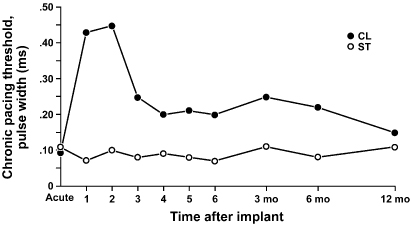
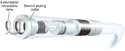
Fig. 1.6 Diagram of a steroid-eluting active fixation lead. The electrode has a porous, platinized tip. A silicone rubber collar is impregnated with 1 mg of dexamethasone sodium.
Transvenous pacing leads have used passive or active fixation mechanisms to provide a stable electrode–myocardium interface. Active fixation leads may have higher initial pacing thresholds acutely at implantation, but thresholds frequently decline significantly within the first 5–30 min after placement.16 This effect has been attributed to hyperacute injury due to advancement of the screw into the myocardium. On a cellular level, implantation of a transvenous pacing lead results in acute injury to cellular membranes, which is followed by the development of myocardial edema and coating of the electrode surface with platelets and fibrin. Subsequently, various chemotactic factors are released, and an acute inflammatory reaction develops, consisting of mononuclear cells and polymorphonuclear leukocytes. After the acute response, release of proteolytic enzymes and oxygen free radicals by invading macrophages accelerates cellular injury. Finally, fibroblasts in the myocardium begin producing collagen, leading to production of the fibrotic capsule surrounding the electrode. This fibrous capsule ultimately increases the effective radius of the electrode, with a smaller increase in surface area.20,21 Steroid-eluting leads are believed to minimize fibrous capsule formation. In both atrial and ventricular active fixation leads, steroid elution results in long-term reduction in energy consumption with maintenance of stimulation thresholds, lead impedance values, and sensing thresholds.22,23
The stimulation threshold may vary slightly with a circadian pattern, generally increasing during sleep and decreasing during the day, probably reflecting changes in autonomic tone. The stimulation threshold may also rise after eating; during hyperglycemia, hypoxemia, or acute viral illnesses; or as a result of electrolyte fluctuations. In general, these threshold changes are minimial. However, in the setting of severe hypoxemia or electrolyte abnormalties they can lead to loss of capture. Certain drugs used in patients with cardiac disease may also increase pacing thresholds (see Chapter 8: Programming).
The inflammatory reaction and subsequent fibrosis that occur after lead implantation may act as an insulating shield around the electrode. These processes effectively increase the distance between the electrode and the excitable tissue, allowing the stimulus to disperse partially before reaching the excitable cells. These changes result in an increased threshold for stimulation and attenuate the amplitude and slew rate of the endocardial signal being sensed. This is a process termed “lead maturation.” Improvements in electrode design and materials have reduced the severity of the inflammatory reaction and thus improved lead maturation rates.18,24 When the capture threshold exceeds the programmed output of the pacemaker, exit block will occur; loss of capture will result if the capture threshold exceeds the programmed output of the pacemaker.16,25 Exit block, a consequence of lead maturation, results from the progressive rise in thresholds over time.16,25 This phenomenon occurs despite initial satisfactory lead placement and implantation thresholds, often but not always occurs in parallel in the atrium and ventricle, and usually recurs with placement of subsequent leads. Steroid-eluting leads prevent exit block in most, but not all patients (Fig. 1.6).
Sensing
The first pacemakers functioned as fixed-rate, VOO devices. All contemporary devices offer demand-mode pacing, which pace only when the intrinsic rate is below the programmed rate. For such devices to function as programmed, accurate and consistent sensing of the native rhythm is essential.
Intrinsic cardiac electrical signals are produced by the wave of electrical current through the myocardium (Fig. 1.7). As the wavefront of electrical energy approaches an endocardial unipolar electrode, the intracardiac electrogram records a positive deflection. As the wavefront passes directly under the electrode, a sharp negative deflection is recorded, referred to as the intrinsic deflection.26 The intrinsic deflection is inscribed as the advancing wavefront passes directly underneath a unipolar electrode. Smaller positive and negative deflections preceding and following the intrinsic deflection represent activation of surrounding myocardium. The analog on the surface ECG is the peak of the R wave, referred to as the intrinsicoid deflection, because the electrical depolarization is measured at a distance (from the surface), rather than directly on the myocardium. However, the intrinsic deflection is a local endocardial event; it does not necessarily time with the intrinsicoid deflection in any ECG lead. Bipolar electrograms (Fig. 1.7) represent the difference in potential recorded between two closely spaced intracardiac electrodes. Due to the close spacing of two typically small electrodes, far-field signals (i.e., signals not generated by the tissue the lead electrode is in contact with) are smaller and thus more easily rejected by pacemakers and defibrillators. Ventricular electrograms typically are much larger than atrial electrograms because ventricular mass is greater. Typical amplitude ranges for ventricular electrograms are 5–25 mV, and for atrial electrograms 1.5–5 mV (Fig. 1.8). The maximum frequency densities of electrograms in sinus rhythm are in the range of 80–100 Hz in the atrium and 10–30 Hz in the ventricle (these frequencies may differ slightly depending on leads and/or technologies). Pulse generator filtering systems are designed to attenuate signals outside of these ranges. Filtering and use of blanking and refractory periods (discussed later) have markedly reduced unwanted sensing, although myopotential frequencies (ranging from 10 to 200 Hz) considerably overlap with those generated by atrial and ventricular depolarization and are difficult to filter out, especially during sensing in a unipolar configuration.27–29 Shortening of the tip-to-ring spacing has also improved atrial sensing and rejection of far-field R waves.
Fig. 1.7 Schema of the relationship of the pacing lead to the recorded electrogram with unipolar (left) and bipolar (right) sensing. Top left: as the electrical impulse moves toward the cathode (lead tip), a positive deflection is created in the electrogram. Middle left: as the electrical impulse passes the cathode, the deflection suddenly moves downward, at the intrinsic deflection. Bottom left: as the impulse moves away from the cathode, a negative deflection occurs. The right panel shows the same phenomena occur for each electrode of a bipolar lead when considered independendently (uni-1 and uni-2). When these are put together as a bipolar signal, the resultant tracing is seen at bottom (bipolar 1–2).
(Adapted from Stevenson WG, Soejima K. Recording techniques for clinical electrophysiology. J Cardiovasc Electrophysiol 2005; 16:1–6.)
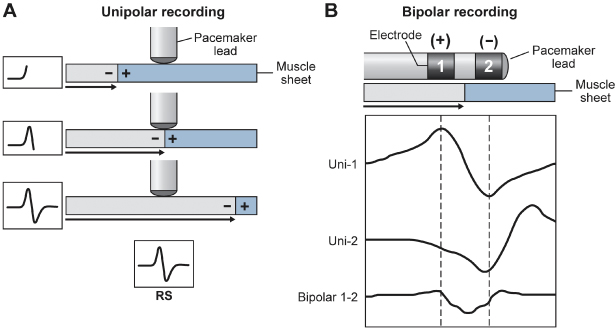
Fig. 1.8 In the intracardiac electrogram, the difference in voltage recorded between two electrodes is the amplitude, which is measured in millivolts. The slew rate is volts per second and should be at least 0.5.
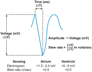
A second important metric of the intracardiac electrogram in addition to amplitude is the slew rate, i.e., the peak slope of the developing electrogram30 (Fig. 1.8). The slew rate represents the maximal rate of change of the electrical potential between the sensing electrodes and is the first derivative of the electrogram (dV/dt). An acceptable slew rate should be at least 0.5 V/s in both the atrium and the ventricle. In general, the higher the slew rate, the higher the frequency content and the more likely the signal will be sensed. Slow, broad signals, such as those generated by the T wave, are less likely to be sensed because of a low slew rate and lower frequency density.
Polarization also affects sensing function. After termination of the pulse stimulus, an excess of positive charge surrounds the cathode, which then decays until the cathode is electrically neutral. Afterpotentials can be sensed, resulting in inappropriate inhibition or delay of the subsequent pacing pulse (Fig. 1.9). The amplitude of afterpotentials is directly related to both the amplitude and the duration of the pacing pulse; thus, they are most likely to be sensed when the pacemaker is programmed to high voltage and long pulse duration in combination with maximal sensitivity.30 The use of programmable sensing refractory and blanking periods has helped to prevent the pacemaker from reacting to afterpotentials, although in dual-chamber systems, atrial afterpotentials of sufficient strength and duration to be sensed by the ventricular channel may result in inappropriate ventricular inhibition (crosstalk), especially in unipolar systems.31,32 Afterpotentials may be a source of problems in devices with automatic threshold measurement and capture detection; the use of leads designed to minimize afterpotentials may increase the effectiveness of such algorithms.33
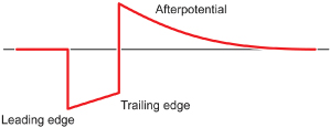
Fig. 1.9 Diagram of a pacing pulse, constant voltage, with leading edge and trailing edge voltage and an afterpotential with opposite polarity. As described in the text, afterpotentials may result in sensing abnormalities.
“Source impedance” is the impedance from the heart to the proximal portion of the lead, and it results in a voltage drop from the site of the origin of the intracardiac electrogram to the proximal portion of the lead.34 Components include the resistance between the electrode and the myocardium, the resistance of the lead conductor material, and the effects of polarization. The resistance between the electrode and the myocardium, as well as polarization, is inversely related to the surface area of the electrode; thus, the effects of both can be minimized by a large electrode surface area. The electrogram actually seen by the pulse generator is determined by the ratio between the sensing amplifier (input) impedance and the lead (source) impedance. Less attenuation of the signal from the myocardium occurs when there is a greater ratio of input impedance to source impedance. Clinically, impedance mismatch is seen with insulation or conductor failure, which results in sensing abnormalities or failure.
Lead Design
Pacing lead components include the electrode and fixation device, the conductor, the insulation, and the connector pin (Figs 1.10 and 1.11). Leads function in the harsh environment of the human body, and are subject to biologic, chemical, and mechanical repetitive stress. They must be constructed of materials that provide mechanical longevity, stability, and flexibility; they must satisfy electrical conductive and resistive requirements; they must be insulated with material that is durable and that has a low friction coefficient to facilitate implantation; and they must include an electrode that provides good mechanical and electrical contact with the myocardium. Industry continues to improve lead design to achieve these goals.
Fig. 1.10 (A) Basic components of a passive fixation pacing lead with tines. (B) Active fixation lead in which the helix serves as the distal electrode.
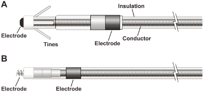
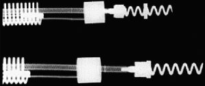
Fig. 1.11 Radiographic example of an active fixation screw-in lead with a retractable screw rather than a screw that is always extended. The screw is extended in the lower image.
Optimal stimulation and sensing thresholds favor an electrode with a small radius and a large surface area. Electrode shape and surface composition have evolved over time. Early models utilized a round, spherical shape with a smooth metal surface. Electrodes with an irregular, textured surface allow for increased surface area without an increase in electrode radius.15,33,35 To achieve increased electrode surface area, manufacturers have used a variety of designs, including microscopic pores, coatings of microspheres, and wire filament mesh.
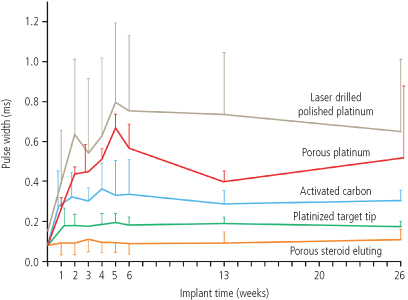
Unfortunately, relatively few conductive materials have proven to be satisfactory for use in pacing electrodes. Ideally, electrodes are biologically inert, resist degradation over time, and do not elicit a marked tissue reaction at the myocardium–electrode interface. Certain metals, such as zinc, copper, mercury, nickel, lead, and silver, are associated with toxic reactions with the myocardium. Stainless steel alloys are susceptible to corrosion. Titanium, tantalum, platinum, and iridium oxide acquire a surface coating of oxides that impedes current transfer. Materials currently in use are platinum–iridium, platinized titanium-coated platinum, iridium oxide, and platinum (Fig. 1.12). Carbon electrodes seem to be least susceptible to corrosion. Also, they are improved by activation, which roughens the surface to increase the surface area and allow for tissue ingrowth.36
Fig. 1.12 Capture thresholds from implantation to 26 weeks from a variety of unipolar leads with similar geometric surface area electrodes. From top to bottom, the curves represent laser drilled polished platinum; porous surface platinum; activated carbon; platinized target tip; and porous steroid eluting leads.
(From Stokes KB, Kay GN. Artificial electric cardiac stimulation. In: Ellenbogen KA, Kay GN, Wilkoff BL, eds. Clinical Cardiac Pacing. Philadelphia: WB Saunders Co., 1995: 3–37, by permission of the publisher.)
Lead fixation may be active or passive. Passive fixation endocardial leads usually incorporate tines at the tip that become ensnared in trabeculated tissue in the right atrium or ventricle, providing lead stability. Leads designed for coronary venous placement usually incorporate a design that wedges the lead against the wall of the coronary vein. Active fixation leads deploy an electrically active screw into the myocardium to provide lead stability. There are advantages and disadvantages to active and passive designs. Passive fixation leads are simple to deploy. However, considerable myocardial and fibrous tissue enveloping the tip typically develops with passive fixation leads. The encasement of the tines of a passive fixation lead by fibrous tissue often makes the extraction of passive fixation leads more difficult than that of active fixation leads. Active fixation leads are often preferable in patients with distorted anatomy, such as those with congenital cardiac defects or those with surgically amputated atrial appendages. Active fixation leads are also preferable in patients with high right-sided pressures. As alternative site pacing has evolved, i.e., the placements of leads outside the right atrial appendage and right ventricular apex, screw-in leads have become more popular because of the ability to stabilize them mechanically in nontraditional locations.
In active fixation leads, various mechanism are used to keep the screw unexposed (to avoid tissue injury) until it is in position for fixation. In many leads, the helix is extendable and retractable by rotation of the proximal connector using a simple tool (Bisping screwdriver). This allows the operator to control the precise time and location of helix deployment. Another approach entails covering a fixed helix with a material such as mannitol which dissolves in the blood stream after approximately 5 minutes. This permits placement of the lead atraumatically at the desired location. Fixation is accomplished by rotating the entire lead body.
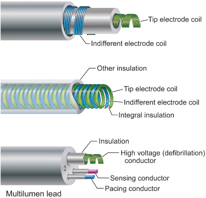
Conductors are commonly of a multifilament design to provide tensile strength and reduce resistance to metal fatigue (Fig. 1.13). Alloys such as MP35N (cobalt, nickel, chromium, and molybdenum) and nickel silver are typically used in modern pacing leads. Bipolar leads may be of coaxial design, with an inner coil extending to the distal electrode and an outer coil terminating at the proximal electrode (Fig. 1.14). This design requires that the conductor coils be separated by a layer of inner insulation. Coaxial designs remain commonly used in the treatment of bradyarrhythmias. Some bipolar leads are coradial, or “parallel-wound”; that is, two insulated coils are wound next to each other. Leads may also be constructed with the conductor coils parallel to each other (multiluminal), again separated by insulating material (Fig. 1.14). This type of design is typically used for tachyarrhythmia leads. Additionally, leads may use a combination of coils and cables. The coil facilitates the passage of a stylet for lead implantation, and the cable allows a smaller lead body.
Fig. 1.13 Conductor coils may be of unifilar, multifilar, or cable design. The multifilar and cable designs allow the conductor to be more flexible and more resistant to fracture.
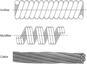
Fig. 1.14 Varieties of conductor construction. Top: bipolar coaxial design with an inner multifilar coil surrounded by insulation (inner), an outer multifilar coil, and outer insulation. Middle: individually insulated wires wound together in a single multifilar coil for bipolar pacing. Bottom: multilumen lead body design in which each conductor has its own lumen.
Two materials have predominated in lead insulation: silicone and polyurethane. Each has its respective advantages and disadvantages, but the overall performances of both materials have been excellent.37 Table 4.2 in Chapter 4 compares the advantages and disadvantages of these two insulating materials.
The two grades of polyurethane that have had the widest use are Pellathane 80A (P80A) and Pellathane 55D. Early after the introduction of polyurethane as an insulating material, it became clear that clinical failure rates with specific leads were higher than acceptable; further investigation revealed that the failures were occurring primarily in leads insulated with the P80A polymer.35,38 Microscopic cracks developed in the P80A polymer, initially occurring as the heated polymer cooled during manufacture; with additional environmental stress, these cracks propagated deeper into the insulation, resulting in failure of the lead insulation.
Polyurethane may also undergo oxidative stress in contact with conductors containing cobalt and silver chloride, resulting in degradation of the lead from the inside and subsequent lead failure. Some current leads use silicone with a polyurethane coating, incorporating the strength and durability of silicone with the ease of handling of polyurethane while maintaining a satisfactory external lead diameter. Silicone rubber is well known to be susceptible to abrasion wear, cold flow due to cyclic compression, and wear from lead-to-lead and lead-to-can contact. Current silicone leads have surface modifications that improve lubricity and reduce friction in blood. Preliminary studies have suggested that a hybrid coating of silicone and polyurethane may offer improved wear.39 Despite lead improvements, laboratory testing, and premarketing, clinical trials have been inadequate to predict the long-term performance of leads, so that clinicians implanting the devices or performing follow-up in patients with pacing systems must vigilantly monitor lead status. Increasingly, the use of internet-enabled remote monitoring and pulse generator based algorithms permits automatic alert generation in the event of impending lead fracture.
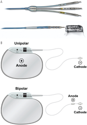
Contemporary leads and connectors are standardized to conform to international guidelines (IS-1 standard), which mandate that leads have a 3.2-mm diameter inline bipolar connector pin.40 These standards were established many years ago because some leads and connector blocks were incompatible, requiring the development of multiple adaptors. The use of the IS-1 standard permits using one manufacturer’s leads with another manufactuer’s pulse generator. Similarly, the DF-1 standard insures a common site for high-voltage connections in defibrillators. The newer IS-4 standard permits a single inline connection of four low-voltage electrodes, permitting coronary sinus leads to include four (rather than two) pacing sites, increasing the likelihood of a lead having an acceptable threshold and/or pacing site. The DF-4 connectors (Fig. 1.15A) contain two high-voltage and two low-voltage connections so that a single connector (with single screw) can provide pace-sense and dual coil defibrillation support, significantly decreasing pocket bulk. The limitation introduced by the DF-4 connector is the inability to use a separate lead and connect it to the proximal coil port in the header. While not commonly required, this is useful when the defibrillation threshold (DFT) is high and a strategy of placing a defibrillation coil in the coronary sinus, azygous vein, or subcutaneous tissues is planned.
Fig. 1.15 Lead connectors and configurations. (A) Connector types in defibrillator leads. The top panel shows the proximal end of a defibrillation lead with a three connectors. Top and bottom pins are DF-1 connectors used for high voltage shock delivery for defibrillation, while the middle pin is an IS-1 connector used for pacing and sensing. Bottom images shows a DF-4 connector, in which all four conductors (two for defibrillation and two for pace/sense) are mounted on a single pin. (B) Unipolar vs. bipolar leads pacing leads. In a unipolar configuration, the pacemaker case serves as the anode, or (+), and the electrode lead tip as the cathode, or (−). In a bipolar configuration, the anode is located on the ring, often referred to as the “ring electrode,” proximal to the tip, or cathode. The distance between tip and ring electrode varies among manufacturers and models.
Bipolar and Unipolar Pacing and Sensing
In unipolar pacing systems, the lead tip functions as the cathode and the pulse generator as the anode (unipolar vs. bipolar leads; Fig. 1.15B). In bipolar systems, the lead tip serves as the cathode and a lead ring acts as the anode (Fig. 1.15B). Unipolar leads are of simpler design (only one conductor) and have a smaller external diameter. Unipolar leads have historically demonstrated greater durability than bipolar leads. In recent years the difference in durability has been less distinct. Unipolar leads do not offer the option of bipolar function. Although unipolar and bipolar leads are readily available, present usage of transvenous leads is almost exclusively bipolar in the USA. Bipolar leads may function in the unipolar mode if the pacemaker is so programmed. They are available in several designs, generally coaxial or multiluminal. Regardless of design, the external diameter of a bipolar lead is usually greater than that of unipolar leads because each coil must be electrically separated by insulating material. Bipolar pacing is generally preferred over unipolar pacing because it cannot cause extracardiac stimulation at the pulse generator (pectoralist muscle stimulation), which may occasionally occur with unipolar pacing due to current returning to the generator. Also, because closely spaced electrodes result in a smaller “antenna,” bipolar sensing is less susceptible to myopotential and far-field oversensing and to electromagnetic interference.41 All implantable defibrillators utilize bipolar sensing to minimize the risk of inappropriate shock caused by oversensing.
There are historical controversies regarding unipolar versus bipolar pacing and sensing configurations and which, if either, is superior.41 Nonetheless, the majority of leads implanted are bipolar. There are certain advantages with unipolar leads. They employ a simpler design and smaller size. Smaller, more compliant and flexible unipolar leads can be placed in difficult coronary sinus venous tributaries. Traditionally, they have very low failure rates.42 Unipolar leads are less prone to short circuit when there are insulation breaches (due the absence of an adjacent conductor), although this benefit may be outweighed by their susceptibility to oversensing. Importantly, a lead that is malfunctioning in the bipolar mode may function satisfactorily when programmed to the unipolar configuration (see Chapter 8: Programming).
All pulse generators offer independently programmable pacing and sensing in each channel; however, bipolar programming of a device attached to a unipolar lead results in no output. Bipolar leads can function in the unipolar mode; the converse is not true.
Left Ventricular Leads
Cardiac resynchronization therapy with biventricular pacing is an established treatment for patients with chronic moderate–severe congestive heart failure, low left ventricular ejection fraction, and New York Heart Association class III or IV heart failure.43 In order to pace the left ventricle, a pacing lead is implanted transvenously through the coronary sinus and one of its venous tributaries to stimulate the left ventricular free wall. Resynchronization is obtained by stimulating both ventricles to contract with minimal intraventricular delay, thereby improving the left ventricular performance.44
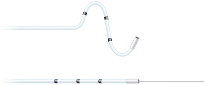
New technologies have emerged to assist in the placement of leads to targeted anatomic sites. Catheter-delivered systems use a deflectable sheath that is braided to allow the simultaneous ability to torque and advance the catheter. A second, smaller lumen sheath can be used within the first sheath to enhance access to the coronary sinus and its venous tributaries, as well as serve as a conduit for contrast injections and lead delivery. A second technology developed to reach difficult anatomic targets is to use an over-the-wire lead delivery system (Fig. 1.16). With this system the lead can be advanced to a stable position over a guidewire used initially to navigate tortuous regions of the coronary veins similar to techniques used extensively for coronary angiography. Using stiffer wires like a stylette that do not exit the left ventricular lead, the leads can be pushed into position as well as have their relative geometries changed by the constraints of the stiff wire. Tip geometry changes allow the operator to change the early contour of the lead system dynamically to allow passage through tortuous veins. Flexibility in tool selection improves access to target sites across a broad range of anatomies and decreases injury to coronary venous structures. Through availability and/or combining of these multiple technologies, access to target sites has improved greatly, in particular, coronary vein subselection for left ventricular lead placement.
Fig. 1.16 Over the wire leads to facilitate placement in coronary vein branches. Top: lead with wire advanced beyond the distal end. The wire acts as a track over which the lead is advanced to provide stability. Bottom: lead with wire removed for final deployment.
Modifications of tip geometries as well as a family of left ventricular leads to choose from have improved the stability of these passive leads. Furthermore, newer multipolar left ventricular leads provide a broad array of pacing configurations to facilitate favorable pacing thresholds and avoid phrenic nerve stimulation.45 Establishing a well-positioned left ventricular lead position, and avoiding apical pacing, favorably influence long-term outcomes with cardiac resynchronization.46
Pulse Generators
All pulse generators include a power source, an output circuit, a sensing circuit, a timing circuit, and a header with a standardized connector (or connectors) to attach a lead (or leads) to the pulse generator.47 Essentially, all devices are capable of storing some degree of diagnostic information that can be retrieved at a later time. Most pacemakers incorporate a rate-adaptive sensor. Despite increasing complexity, device size has continued to decrease. This has led to a variable effect on the potential longevity.
Many power sources have been used for pulse generators over the years. Lithium iodine cells have been the energy source for almost all contemporary pacemaker pulse generators. Newer pacemakers and implantable cardioverter-defibrillators (ICDs) that can support higher current drains for capacitor charging and high-rate antitachycardia pacing use lithium–silver oxide–vanadium chemistries. Lithium is the anodal element and provides the supply of electrons; iodine is the cathodal element and accepts the electrons. The cathodal and anodal elements are separated by an electrolyte, which serves as a conductor of ionic movement but a barrier to the transfer of electrons. The circuit is completed by the external load, i.e., the leads and myocardium. The battery voltage of the cell depends on the chemical composition of the cell; at the beginning of life for the lithium iodine battery, the cell generates approximately 2.8 V, which decreases to 2.4 V when approximately 90% of the battery life has been used. The voltage then exponentially declines to 1.8 V as the battery reaches end-of-life. However, the voltage at which the cell reaches a specific degree of discharge is load dependent. The elective replacement voltages were chosen based on the shape of the discharge curves under expected operating conditions. When the battery is at end-of-service, most devices lose telemetry and programming capabilities, frequently reverting to a fixed high-output pacing mode to maintain patient safety. This predictable depletion characteristic has made lithium-based power cells common in current devices. Nickel–cadmium technology is being used once again in at least one investigational implantable device.
The battery voltage can be telemetered from the pulse generator. In addition, most devices provide battery impedance (which increases with battery depletion) for additional information about battery life. The battery life can also be estimated by the magnet rate of the device, which changes with a decline in battery voltage. Unfortunately, the magnet rates are not standardized, and rate change characteristics vary tremendously among manufacturers and even among devices produced by the same manufacturer. Therefore, it is important to know the magnet rate characteristics of a given device before using this feature to determine battery status.
The longevity of any battery is determined by several factors, including chemical composition of the battery, size of the battery, external load (pulse duration and amplitude, stimulation frequency, total pacing lead impedance, and amount of current required to operate device circuitry and store diagnostic information), amount of internal discharge, and voltage decay characteristics of the cell. The basic formula for longevity determination is 114 × [battery capacity (A-HR)/current drain (µA)] = longevity in years. However, this formula is subject to how the power cell’s ampere-hours is specified by the manufacturer; thus, the longevity will vary somewhat by company. High-performance leads, automatic capture algorithms, and programming options that minimize pacing may further enhance device longevity if not offset by energy consumption from running the software.48,49
The pacing pulse is generated first by charging an output capacitor with subsequent discharge of the capacitor to the pacing cathode and anode. Because the voltage of a lithium iodine cell is fixed, obtaining multiple selectable pulse amplitudes requires the use of a voltage amplifier between the battery and the output capacitor. Contemporary pulse generators are constant-voltage (rather than constant-current) devices, implying delivery of a constant-voltage pulse throughout the pulse duration. In reality, some voltage drop occurs between the leading and the trailing edges of the impulse; the size of this decrease depends on the pacing impedance and pulse duration. The lower the impedance, the greater the current flow from the fixed quantity of charge on the capacitor and the greater the voltage drop throughout the pulse duration.50 The voltage drop is also dependent on the capacitance value of the capacitor and the pulse duration.
The output waveform is followed by a low-amplitude wave of opposite polarity, the afterpotential. The afterpotential is determined by the polarization of the electrode at the electrode–tissue interface; formation is due to electrode characteristics as well as to pulse amplitude and duration. The sensing circuit may sense afterpotentials of sufficient amplitude, especially if the sensitivity threshold is low. Newer pacemakers use the output circuit to discharge the afterpotential quickly, thus lowering the incidence of afterpotential sensing. The afterpotential also helps to prevent electrode corrosion.
The intracardiac electrogram results from current conducted from the myocardium to the sensing circuit via the pacing leads, where it is then amplified and filtered. The input impedance must be significantly larger than the sensing impedance to minimize attenuation of the electrogram. A bandpass filter attenuates signals on either side of a center frequency, which varies between manufacturers (generally ranging from 20 to 40 Hz).51,52 After filtering, the electrogram signal is compared with a reference voltage, the sensitivity setting; signals with an amplitude of this reference voltage or higher are sensed as true intracardiac events and are forwarded to the timing circuitry, whereas signals with an amplitude below the reference amplitude are categorized as noise, extracardiac or other cardiac signal, such as T waves.
Sensing circuitry also incorporates noise reversion that cause the pacemaker to revert to a noise reversion mode (asynchronous pacing) whenever the rate of signal received by the sensing circuit exceeds the noise reversion rate. This feature is incorporated to prevent inhibition of pacing when the device is exposed to electromagnetic interference. Pulse generators also use Zener diodes designed to protect the circuitry from high external voltages, which may occur, for example, with defibrillation. When the input voltage presented to the pacemaker exceeds the Zener voltage, the excess voltage is shunted back through the leads to the myocardium.
The timing circuit of the pacemaker is an electronic clock that regulates the pacing cycle length, refractory periods, blanking periods, and AV intervals with extreme accuracy. The output from the clock (as well as signals from the sensing circuitry) is sent to a timing and logic control board that operates the internal clocks, which in turn regulate all the various timing cycles of the pulse generator. The timing and logic control circuitry also contains an absolute maximal upper rate cut-off to prevent “runaway pacing” in the event of random component failure.53,54
Each new generation of pacemakers contains more microprocessor capability. The circuitry contains a combination of read-only memory (ROM) and random-access memory (RAM). ROM is used to operate the sensing and output functions of the device, and RAM is used in diagnostic functions. Larger RAM capability has allowed devices to store increased amounts of retrievable diagnostic information and patient-specific longitudinal data, with the potential to allow downloading of new features externally into an implanted device.
Stay updated, free articles. Join our Telegram channel

Full access? Get Clinical Tree


