Pacemakers
Overview
An artificial pacemaker is an electronic device that generates and transmits an electrical stimulus to the atria, the ventricles, or both, resulting in depolarization, followed by muscle contraction. The use of artificial pacemakers may be necessitated when there is a significant malfunction of the heart’s electrical system, usually involving the sinus node, the atria, or the atrioventricular (AV) conduction pathways. The result may be a slow, fast, or irregular rhythm, which can affect the heart’s pumping ability and may lead to a decrease in cardiac output and in the quality of life. Some indications for pacing include:
▪ Sinoatrial dysfunction
1. Sinus bradycardia
2. Sinus arrest
3. Sinus exit block
4. Atrial flutter or fibrillation
5. Sick sinus syndrome (rhythms in which there is marked bradycardia alternating with periods of tachycardia, especially atrial flutter or fibrillation; also called tachy-brady syndrome).
6. Chronotropic incompetence (sinus node is not capable of increasing its rate in response to activity
▪ AV block
1. Second-degree AV block, Mobitz II
2. Third-degree AV block
▪ Hypersensitive carotid sinus — Stimulation of the carotid sinus that causes episodes of asystole resulting in recurrent syncope; stimulators may include turning the head from side to side, or wearing a tight necktie or collar.
Pacemakers may be inserted on a temporary or permanent basis depending on the clinical situation. Temporary pacing is appropriate in emergent situations (transient symptomatic bradycardias or AV block associated with myocardial ischemia or drug toxicity). Temporary pacing may also be used to provide prophylactic therapy for high-risk patients during cardiac catheterization, during and after cardiac surgery, and to override tachyarrhythmias (overdrive pacing). Permanent pacemaker implantation is considered for unresolved rhythms or conditions in which clinical symptoms are present and for which long-term pacing is indicated.
A pacemaker system (Figures 10-5 and 10-6) consists of a pulse generator and a pacing lead:
▪ Pulse generator — The pulse generator houses a battery, a lead connector, and electronic circuitry for pacemaker settings.
▪ Pacing lead — The pacing lead has one or two metal poles (electrodes) at the tip of the catheter that come in contact with the endocardium (Figure 10-1). A lead with only one electrode at its tip is called a unipolar pacing system. A lead with two electrodes at its tip is called a bipolar pacing system. The pacing lead serves as a transmission line between the pulse generator and the endocardium. Electrical impulses are transmitted from the pulse generator (through the pacing lead) to the endocardium, while information about intrinsic electrical activity is relayed from the electrode tip (through the pacing lead) back to the generator. If the generator responds by sending a pacing impulse to the heart, it is called triggering. If a pacing impulse is not sent to the heart, this is called inhibition. Many permanent pacing leads are constructed with fixation devices (screws, tines, or barbs) that help guarantee long-term contact with the endocardium. Temporary pacing leads are not constructed with fixation devices so they can be easily removed when pacing is no longer required.
Pacemakers can function in a fixed rate mode or a demand mode:
▪ Fixed rate mode (asynchronous) — Fixed rate pacemakers initiate impulses at a set rate, regardless of the patient’s intrinsic heart rate. This mode of pacing is known as asynchronous pacing because it’s not synchronized to sense the patient’s own heart rhythm. This may result in competition between the patient’s natural (intrinsic) rhythm and that produced by the pacemaker. Ventricular tachycardia or ventricular fibrillation may be induced if the pacing stimulus falls during the vulnerable period of the cardiac cycle. Fixed rate pacemakers are rarely used today.
▪ Demand mode (synchronous) — A demand pacemaker paces only when the heart fails to depolarize on its own (fires only “on demand”). Demand pacemakers are designed with a sensing mechanism that inhibits discharge when the patient’s heart rate is adequate and a pacing mechanism that triggers the pacemaker to fire when no intrinsic activity occurs within a preset period. This mode of pacing is called synchronous pacing because
it is synchronized to sense the patient’s cardiac rhythm. Demand pacing is the most commonly used pacemaker mode today.
it is synchronized to sense the patient’s cardiac rhythm. Demand pacing is the most commonly used pacemaker mode today.
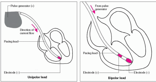 Figure 10-1. Unipolar and bipolar pacing leads. |
A pacemaker system may be single- or dual-chamber:
▪ Single-chamber — A single-chamber pacemaker system uses one lead inserted into either the right atrium or the right ventricle. This pacemaker can sense and pace only the chamber into which it is inserted.
If a single-chamber atrial pacemaker senses a P wave, the pacemaker is inhibited from firing an electrical stimulus. If it does not sense a P wave, the pacemaker sends an electrical stimulus to the atrium. Stimulation of the atrium produces a pacemaker spike (a vertical line on the ECG), followed by a P wave (Figure 10-2, example A).
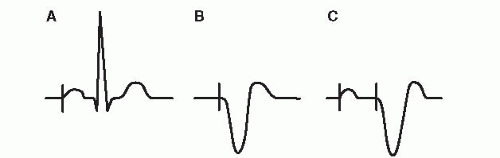 Figure 10-2. Single-chamber and dual-chamber pacing examples. (A) The single-chamber atrial pacemaker looks for a P wave and fires into the atrium if no P wave is sensed; the pacing spike is followed by a P wave. (B) The single-chamber ventricular pacemaker looks for a QRS complex and fires into the ventricle if no QRS is sensed; the pacing spike is followed by a wide QRS complex. (C) The dual-chamber pacemaker looks for a P wave; if no P wave is sensed, the pacemaker delivers a stimulus into the atrium; the pacing spike is followed by a P wave. After a programmed electronic PR interval (the AV interval), if no QRS is sensed, a second stimulus is delivered into the ventricle; the pacing spike is followed by a wide QRS complex. |
If a single-chamber ventricular pacemaker senses a QRS complex, the pacemaker is inhibited from firing an electrical stimulus. If it does not sense a QRS complex, the pacemaker sends an electrical stimulus to the ventricle. Stimulation of the ventricle produces a pacemaker spike followed by a wide QRS complex, resembling a ventricular ectopic beat (Figure 10-2, example B). Single-chamber ventricular pacing is the most commonly used temporary type of pacing and is also frequently used for permanent pacing. Single-chamber atrial or ventricular pacing can be used with epicardial pacing wires.
▪ Dual-chamber — A dual-chamber pacemaker system uses two leads, one going to the right atrium and the other
to the right ventricle. The dual-chamber pacemaker can sense and pace in both chambers.
to the right ventricle. The dual-chamber pacemaker can sense and pace in both chambers.
If a dual-chamber pacemaker senses a P wave, the pacemaker is inhibited from firing an electrical stimulus. If the pacemaker does not sense a P wave, the pacemaker sends an electrical stimulus to the atrium. Stimulation of the atrium produces a pacemaker spike, followed by a P wave. The pacemaker is programmed to wait, simulating an electronic PR interval. In pacing terminology the artificial PR interval is called the AV interval. If a dual-chamber pacemaker senses a QRS complex, it is inhibited from firing an electrical stimulus. If the pacemaker does not sense a QRS complex, the pacemaker will send an electrical stimulus to the ventricle. Stimulation of the ventricle produces a pacemaker spike followed by a wide QRS complex. Figure 10-2, example C, shows stimulation of the atria and the ventricle by a dual-chamber pacemaker.
Dual-chamber pacemakers are often called AV sequential pacemakers because of their ability to stimulate the atria and ventricles in sequence (first the atria, then the ventricles), mimicking normal heart physiology and thus preserving the atrial kick.
Dual-chamber pacemakers are frequently used with permanent pacing and can also be used with epicardial pacing. Dual-chamber temporary pacing can be done, but it is difficult to place temporary atrial wires and it is not as reliable as ventricular pacing.
Temporary pacemakers
Temporary pacing can be accomplished with transcutaneous (external), transvenous, or epicardial methods:
▪ Transcutaneous pacing (TCP) — TCP refers to the delivery of a pacing stimulus to the heart through pads placed on the patient’s outer chest (Figure 10-3). Requirements for TCP include pacing pads, a pacing cable, and a defibrillator monitor with pacing capabilities. TCP is recommended as the initial pacing method of choice in emergent cardiac situations. External pacemakers are noninvasive, effective, and quick and easy to apply. TCP provides only ventricular pacing.
 Figure 10-3. External pacing pad placement (anterior-posterior position). |
TCP is indicated as a treatment for symptomatic bradyarrhythmias (sinus bradycardia, slow atrial flutter or fibrillation, Mobitz II second-degree AV block, or third-degree AV block). TCP is not effective in rhythms without meaningful contractile activity such as ventricular standstill and pulseless electrical activity (PEA) that occur in the setting of cardiac arrest. This is because the primary problem in these situations is the inability of the myocardium to contract when appropriately stimulated.
External pacemakers should not be relied upon for an extended period of time. They should be used only as a temporary measure in emergency situations until transvenous access is available or the cause of the bradyarrhythmia is resolved. Transvenous pacing is still the treatment of choice for patients requiring a temporary but longer period of pacemaker support.
The technique of TCP involves:
1. Attach pacing pads to chest. TCP involves attaching two large pacing pads to the skin surface of the patient’s chest. Multifunction pads have the capability to monitor the heart rhythm, externally pace, and defibrillate through one set of pads. The pads have conductive gel on the inner surface to help transmit the electrical current through the chest wall. The large surface area of the pad and the conductive gel also help minimize the possibility of skin burns from the procedure. If possible, excess hair should be clipped before the pads are applied to maximize contact with the skin surface.
Most manufacturers recommend the pads be placed in an anterior-posterior position. The anterior pad (labeled “front”) is placed to the left of the sternum, halfway between the xiphoid process and the left nipple. In the female patient, the anterior pad should be positioned under the left breast. The posterior pad (labeled “back”) is placed on the left posterior chest directly behind the anterior pad.
Successful TCP requires a higher electrical current output (mA) than conventional transvenous pacing to overcome the resistance of the chest wall. Placement of the pacing pads affects the amount of current required to depolarize the ventricle. The placement that offers the most direct pathway to the heart usually requires the lowest mA in order to pace the heart. Currents of 50 mA or more may be associated with discomfort and sedation may be required.
2. Connect pacing pads to defibrillator or monitor. Connect the pacing pads to a pacing cable and a defibrillator monitor system with pacing capabilities.
3. Initiate pacing. Set the defibrillator or monitor to pace setting. Set the pacing rate first (usually 70), then slowly increase the mA until consistent ventricular capture is seen on the monitor (a pacing spike followed by a wide QRS complex, Figure 10-4). If capture is lost during pacing, the mA may have to be increased.
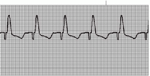 Figure 10-4. Electrical capture of the ventricle with an external pacemaker. This figure shows a square pacing spike (Zoll monitor-defibrillator with external pacemaker). Other external pacemakers may have a different pacing artifact. |
Verify that electrical capture (seen on the monitor) is associated with mechanical capture (verified by palpable pulses). Evaluate pulses on the patient’s right side to avoid confusion between the presence of an actual pulse and skeletal muscle contractions caused by the external pacemaker.
▪ Transvenous pacing — Transvenous pacing refers to the delivery of a pacing stimulus to the heart through a vein (transvenous approach). Requirements for transvenous pacing include an external pulse generator, a pacing lead wire, and a bridging cable to connect the two (Figure 10-5).
Some indications for transvenous pacing include symptomatic bradyarrhythmias (sinus bradycardia, Mobitz II second-degree AV block, and third-degree AV block), prophylactic therapy during cardiac catheterization for high-risk patients, and overdrive pacing of tachyarrhythmias. Transvenous pacing is usually not effective when meaningful contractile activity is absent (ventricular standstill and PEA). For significant unresolved rhythm or conduction disorders, permanent pacing is required.
Temporary pulse generators are externally controlled by manipulating dials on the face of the unit. Removable batteries are contained within the generator housing. Prior to insertion of a pacing lead, prepare the equipment. Insert a new 9-volt battery into the battery compartment; set pacing rate at 100 beats per minute, the mA to 5, and the sensitivity knob to maximum clockwise position for demand (synchronous) pacing. Insert the end of the bridging cable into matching terminals on the pulse generator, and turn pulse generator on to verify proper functioning of the battery and unit.
The preferred routes of access for transvenous pacing are the right internal jugular vein, the right subclavian, and the right femoral vein. The pacing lead is inserted into the vein of choice and guided into the heart using fluoroscopy. Once the wire is visualized in the right atrium, a balloon at the tip of the pacing catheter is inflated and the wire is floated through the tricuspid valve into the apex of the right ventricle for single-chamber ventricular pacing. Even though single-chamber atrial pacing and dual-chamber pacing can be done, single-chamber ventricular pacing is the most reliable and preferred choice for transvenous pacing. Once proper placement is verified, the balloon is deflated. The distal tail of the pacing catheter is connected to the negative connection of the bridging cable and the proximal tail is connected to the positive connection of the bridging cable.
Using the dials on the external pulse generator, adjust the pacemaker settings:
1. Determine voltage threshold. This is the smallest amount of voltage (mA) required to pace the heart. While watching the cardiac monitor, gradually turn down the mA until capture is lost (usually 0.7 to 1.0 mA) and then gradually turn up the mA until capture is regained. The point at which capture is regained is the threshold. Set the mA at twice threshold level.
2. Set pacing rate. This is determined by the physician (usually 70 beats per minute).
3. Set sensitivity. Sensitivity is usually maintained at maximum clockwise position (5 o’clock).
The number of temporary transvenous pacing leads being placed is decreasing, largely due to the improved reperfusion management of acute MI and improved access to permanent pacing systems.
▪ Epicardial pacing — Epicardial pacing refers to the delivery of a pacing stimulus to the heart through wires placed on the epicardial surface of the atrium, ventricle, or both, during cardiac surgery. Two wires are attached to the atrium for single-chamber atrial pacing (one wire serves as ground) or to the ventricle for single-chamber ventricular pacing, or two wires are attached to both chambers for dual-chamber pacing. The wires are loosely sutured to the outer surface of the heart and pulled through the chest wall where they are attached to a bridging cable and an
external pulse generator. Atrial wires usually exit to the right of the sternum and ventricular wires exit to the left. When no longer needed, the wires are gently pulled out through the wound.
external pulse generator. Atrial wires usually exit to the right of the sternum and ventricular wires exit to the left. When no longer needed, the wires are gently pulled out through the wound.
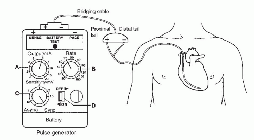 Figure 10-5. Temporary transvenous pacemaker system. A. Output or mA dial Controls the amount of electrical energy delivered to endocardium. Increase mA by turning dial clockwise to higher number; decrease mA by turning dial counterclockwise to lower number. B. Rate dial Determines the heart rate in beats/minute at which the stimulus is to be delivered. C. Sensitivity or mV dial Controls the ability of the generator to sense the electrical activity. In maximum clockwise position (5 o’clock), provides demand (synchronous) pacing. In maximum counterclockwise position (7 o’clock), provides fixed rate (asynchronous) pacing. Increase sensitivity (mV) by turning mV dial clockwise to lower number; decrease sensitivity by turning dial counterclockwise to higher number. D. On/off control Activates/inactivates the pulse generator. |
Epicardial pacing is used after cardiac surgery to treat symptomatic bradyarrhythmias, as a prophylactic measure for high-risk patients, and to treat tachyarrhythmias using overdrive pacing techniques.
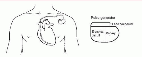 Figure 10-6. Permanent pacemaker system. |
Permanent pacemakers
A permanent pacemaker system (Figure 10-6) refers to an implanted generator and a lead wire (or wires) that is introduced into the heart through a central vein (often the subclavian). The implant procedure is relatively simple, usually performed under local anesthesia and conscious sedation, and lasts about 1 hour. The procedure is facilitated by fluoroscopy, which enables the physician to view
the passage of the lead wire. After satisfactory placement of the pacing lead is confirmed, the lead is connected to the pacemaker generator. The generator is placed in the subcutaneous tissue just below the left or right clavicle. Generally the patient’s nondominant side is chosen to minimize interference with the patient’s daily activities.
the passage of the lead wire. After satisfactory placement of the pacing lead is confirmed, the lead is connected to the pacemaker generator. The generator is placed in the subcutaneous tissue just below the left or right clavicle. Generally the patient’s nondominant side is chosen to minimize interference with the patient’s daily activities.
The major reason for implanting a pacemaker is the presence of a symptomatic bradycardia. Symptomatic bradycardia is a term used to define a bradycardic rhythm that is directly responsible for symptoms such as syncope, transient dizziness, confusion, fatigue, exercise intolerance, congestive heart failure, dyspnea, and hypotension.
Permanent pacemaker technology has undergone major advances since pacemakers were first introduced in the 1950s. Early pacemakers paced a single chamber (the right ventricle) at a fixed rate. Today’s pacemakers function as demand pacemakers, sensing the patient’s natural beats and pacing the heart “on demand” (pacing only when needed). Most of the permanent pacemakers used today are the dual-chamber demand type. Although these dual-chamber models are more expensive, they maintain AV synchrony (the atria pace first, then the ventricles), preserving the atrial kick and often providing patients with a higher quality of life. Studies have shown that unnecessary pacing of the right ventricle can lead to heart failure and an increased incidence of atrial fibrillation. The newer dual-chamber devices can keep the amount of right ventricular pacing to a minimum and thus prevent worsening of the heart disease.
Permanent pacemakers are also available for specific conditions or needs:
▪ Rate-responsive pacemaker — This pacemaker has sensors that detect changes in the patient’s physical activity and automatically adjust the pacing rate to meet the body’s metabolic needs. Rate-responsive pacing mimics the heart’s normal rhythm, enabling patients to participate in more activities.
▪ Biventricular pacemaker — A biventricular pacemaker, also known as cardiac resynchronization therapy (CRT), stimulates both the right and left ventricles. By pacing both ventricles, the pacemaker can resynchronize a heart whose opposing walls do not contract in synchrony (a problem that occurs in 25% to 50% of heart failure patients). CRT devices have been shown to reduce mortality and improve quality of life in patients with an ejection fraction of 35% or less or in patients with heart failure symptoms.
▪ Implantable cardioverter-defibrillators (ICDs) — These devices have the ability to pace for bradycardia, and overdrive pace for tachycardia (antitachycardia pacing) and shock therapy (cardioversion and defibrillation). They are used in the treatment of patients at risk for sudden cardiac death.
Once the pacemaker is implanted, the following information is helpful to share with the patient:
1. Periodic pacemaker checkups — The pacemaker is periodically checked to ensure the device is operational and performing appropriately. This can be done in the physician’s office or over the phone (remote monitoring). Most pacemakers are programmable, enabling the physician to adjust pacing therapy.
2. Pacemaker safety — Built-in filters protect pacemakers from electrical interference from most devices encountered in daily life, including microwave ovens. Security devices at airports should not cause any interference to the normal operation of the pacemaker; however, they may detect the metal in the pacemaker. In this situation, the pacemaker wearer can present an ID card indicating they have a pacemaker. Cell phones do not seem to damage or affect how the pacemaker works. Any activity that involves intense magnetic fields (such as arc welding) should be avoided. Medical tests involving the use of magnetic resonance imaging (MRI) are usually ruled out for patients with pacemakers.
3. Pacemaker replacement — The life of a pacemaker is affected by the type of pacemaker and how it is programmed to pace the heart. Today’s pacemakers usually contain lithium-iodine batteries, which are designed to last many years. Pacemakers have a built-in indicator to signal when the battery is approaching depletion. Most reflect battery depletion by a gradual decrease in the pacing rate. The pacemaker is designed to operate for several months to allow adequate time to schedule a replacement procedure. Because the batteries are permanently sealed inside the pacemaker, the entire pacemaker is replaced when the battery runs down. Device replacement is usually a simpler procedure than the original insertion as it does not normally require leads to be replaced.
Permanent pacemaker identification codes
A universal coding system is used to describe the function of single- and dual-chamber pacemakers (Table 10-1). The code is comprised of five positions. Various letters are used for each position to describe a pacemaker function or characteristic. Only one letter is used per position:
▪ First position — Identifies the chamber paced.
▪ Second position — Identifies the chamber where intrinsic electrical activity is sensed.
▪ Third position — Indicates how the pacemaker will respond when it senses intrinsic electrical activity.
▪ Fourth position — Identifies programmable functions, the capability for transmitting and receiving data (communication), and the availability of rate responsiveness.
▪ Fifth position — Identifies antitachycardia functions:


