Objects/devices
Safety
Prosthetic heart valve or annuloplasty ring
Not considered contraindication
Implanted cardiac pacemaker
Generally not safe (except MR-compatible new ICDs)
Cardiac closure and occluder devices
MR safe
Implanted cardioverter-defibrillator (ICD)
Generally not safe (except MR-compatible new ICDs)
Loop recorder (event monitor)
MR conditional
Inferior vena cava filters
MR safe (most), MR conditional (few)
Hemodynamic support devices (LVAD, IABP, and so on)
Contraindication to MR
Aortic stent graft
MR safe except “Zenith AAA endovascular graft”
Sternal suture wire after surgery
MR safe
Coronary stents and peripheral stents
MR safe (most), MR conditional (a few stents)
22.1.3 Cardiac Gating
The most effective form of cardiac gating is ECG gating which requires a high-amplitude QRS complex. In case of inadequate QRS complex, we can use the peripheral pulse from fingertip pulse monitors. An arrhythmia may lead to inappropriate triggering and image blurring or artifacts. An arrhythmia rejection technique is useful but prolongs the acquisition time.
A prospective ECG gating (Fig. 22.1a)
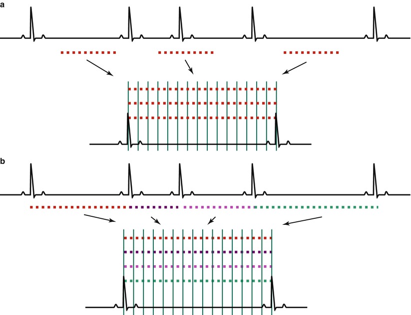
Fig. 22.1
Methods of ECG gating. (a) Prospective ECG gating: we obtain signal data after the determined time from the R wave on ECG. Acquisition time is fixed regardless of the R-R interval. If there is a premature heartbeat, scanning ignores the irregular beat which causes image blurring. (b) Retrospective ECG gating: we obtain signal data throughout the entire R-R interval which will be filled with the allotted k-spaces. Acquisition time is variable according to the heart rate
Provides better temporal resolution images, but results in longer acquisition time
Is not sampled at the end of the cardiac cycle
Can be effective in evaluating cardiac anatomy or tumor
A retrospective ECG gating (Fig. 22.1b)
Can cause image blurring due to combining data from different cardiac cycles
Obtains imaging data from the whole cardiac cycle
Is less sensitive to arrhythmias
Is excellent in cine imaging for assessing regional and global wall motion
22.1.4 Respiratory Fixing
When the images are blurred and signal-to-noise ratio (SNR) is too weak due to the respiratory motion, increasing the number of image acquisitions helps to improve SNR and reduce respiratory motion artifacts [2]. There are different kinds of respiratory fixing methods used in the clinical settings.
Breath-holding by the patient
Is the most commonly used during image acquisition
In standard MR sequences
May be limited in acquisition time
Is less available in the elderly or severely ill patients
Respiratory gating (Fig. 22.2)
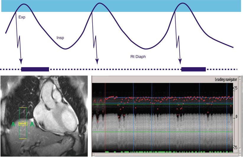
Fig. 22.2
Respiratory gating with navigator echo on the right diaphragm. Scanning is performed when the signal from the right diaphragm is positioned within the acquisition window. Image is good when a gating window is below 5 mm. Exp expiration phase, Insp inspiration phase, and Rt Diaph right diaphragm
Monitors the patients’ diaphragmatic motion
Obtains the images during the end-expiratory phase
With a specified gating window which is acceptable if < 5 mm
May be effective in patient with little cooperation
Can lead to overall extension of scan time
Free breathing mode
22.1.5 Contrast Enhancement
The bolus injection of contrast medium is helpful to increase the signal of the blood or the targeted tissue. 3D MRA study is useful in the evaluation of blood vessels. The early phase of enhancement in the targeted tissue is related to the vascularity of the tissue and also reflects the fractional blood volume of the tissue and the extravascular microcirculation of the contrast medium. The inflammation of the targeted tissue or the higher vascularity of the tumors may represent prominent early enhancement. Differential distribution of contrast medium in early dynamic phases is helpful to differentiate between the normal myocardium and the pathologic myocardium in ischemic conditions.
The late phase of enhancement in the targeted tissue can be used to evaluate the abnormal stasis of the contrast medium which is useful to evaluate the areas of fibrosis. Stasis of contrast medium in the myocardium is made more prominent on the images by using the inversion recovery pulse which suppresses the normal myocardial signal.
Injection of contrast media
Is favorable of bolus injection (with 4–5 mL/s for 2–4 s)
Follows by injection of a bolus of normal saline
To flush the remaining contrast agent out of the injection routes
Contrast media enhancement
Increases SNR for MR angiography
Enables to obtain sequential images of different structures
Such as artery or vein
Improves CNR for tissue characterization
Can be useful in obtaining multiple data sets of the targeted images
For the dynamic perfusion study
Can be utilized in the evaluation of the tumor or inflammation
Using the early contrast pooling images
Is helpful in the evaluation of the infarct myocardium
Using the delayed contrast pooling images
22.1.6 Basic Views of the Heart (Fig. 22.3)
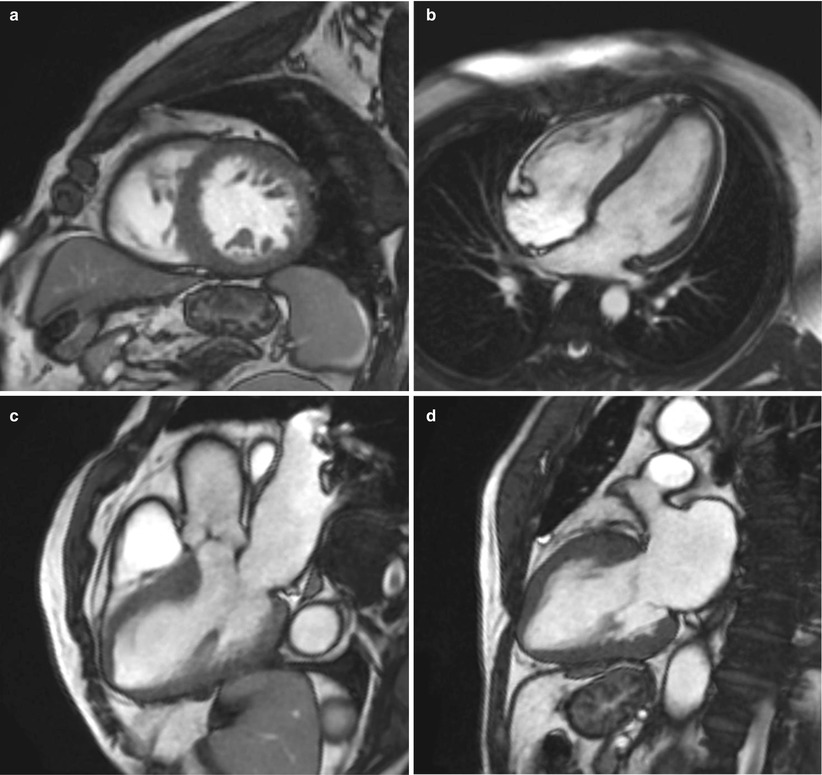
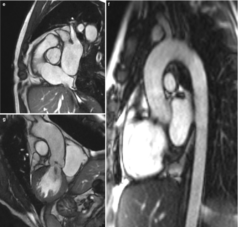
Fig. 22.3
Basic views of the heart. (a) Short-axis view, (b) four-chamber view, (c) three-chamber view, (d) two-chamber view, (e) RV outflow tract view, (f) aortic valve view, and (g) aortic arch (candy-cane) view
The heart is positioned in the thoracic cage with a little oblique direction to the standard view of the thorax. Therefore, cardiac MR images are generally obtained along the long and short axes of the heart rather than those of the thorax. The long axis of the heart is the line from the cardiac base to the apex, and the short axis is the line perpendicular to the long axis of the heart. Although we can obtain all cardiac views through the freely positioned acquisition windows in any orientation, we usually obtain the dedicated views similar to echocardiography to allow assessment of cardiac chamber morphology or function and to communicate effectively among the clinicians.
Two-chamber view
Can be obtained when the imaging plane passes through the center line of the mitral valve to the cardiac apex
Short-axis view
Can be obtained perpendicular to the long axis of the heart from two-chamber or four-chamber views
Four-chamber view
Can be obtained when the imaging plane passes through the center of the left ventricle through the inferior septum of the short-axis view of the heart
Three-chamber view
Can be obtained when the imaging plane passes through the center of the left ventricle and the aortic valve from the basal short-axis view of the heart
RVOT view with pulmonary bifurcation
Can be obtained when the imaging plane passes through the center of the right ventricle and the pulmonic valve from the basal short-axis view of the heart
Aorta arch (candy-cane) view
Can be obtained when the imaging plane passes through the center of the ascending and descending aorta from the axial view of the thorax
22.1.7 Preparation Pulse
MR signal intensity in many situations is too weak to provide an appropriate information from the targeted images. The preparation pulse plays a role to create a preexisting magnetization prior to the application of RF pulses destined for data readout. It was usually applied before the spin echo or gradient echo pulse sequences were performed. Major roles are enhancing tissue contrast and suppressing signal intensity from the targeted tissues. Preparation pulse may prolong the acquisition time.
Inversion pulse (Fig. 22.4)
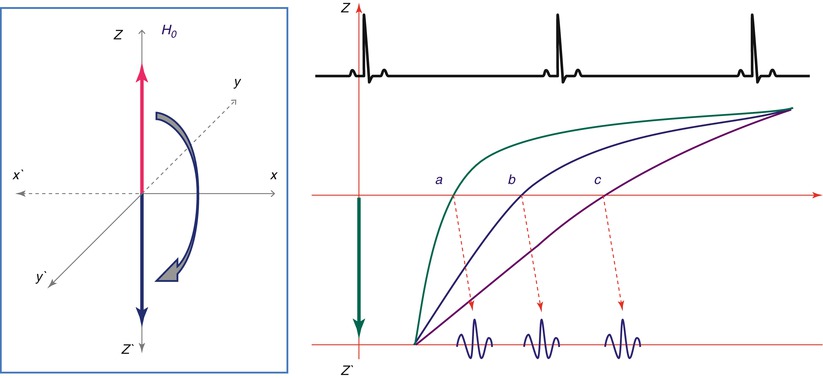
Fig. 22.4
The role of inversion pulse. Inversion pulse uses 180° pulse to reverse longitudinal magnetization. Inversion pulse according to the inversion time can suppress the targeted tissues such as fat, water, myocardium, or blood
Is more effective for T1 weighting in the targeted tissue
Can generate a variety of image contrasts between tissues
Can be used before spin echo or gradient echo
Uses 180° pulse to reverse longitudinal magnetization
Can be used in suppressing the targeted tissues as follows:
1.
Double inversion pulses for black blood technique
2.
Triple inversion pulses for myocardial edema
With fat saturation technique
3.
Single inversion pulse for myocardium suppression
Used in viability imaging studies
T2 preparation pulse
Is more effective for T2 weighting in the targeted tissue
Is commonly used in T2 mapping for edema detection
Uses 90° RF pulse followed by a series of 180° RF pulse, then a −90° RF tip-up
22.2 T1- and T2-Weighted Imaging
MR signal intensities usually depend on the repetition time (TR) and the echo time (TE). The repetition time is the time between consecutive excitations, and the echo time is the time between the excitation and the detection of the signal which are applied for the spin echo or gradient echo. We need to select an appropriate TR or TE to characterize the tissue components.
22.2.1 T1-Weighted Image
The contrast depends on the various T1 time constants of the different tissue types.
Used to visualize anatomy and differentiate fat from the surrounding tissues.
TE is short and TR is usually equal to one R-R interval for spin echo sequence.
Shows higher signal from fat tissue and lower signal from water.
Is very useful for comparison of pre- and post-contrast images.
22.2.2 T2-Weighted Image
TE directly determines how much the transverse signal decays.
Is used to visualize fluid due to edema (inflammation).
TE is longer; overall SNR decreases as TE is increased due to de-phasing.
TR is usually equal to 2 R-R intervals.
Shows a shorter T2 value in fat tissue than in water.
Has variable signal in flowing blood or hematomas.
Can be useful in fat suppression with a short tau inversion recovery
< div class='tao-gold-member'>
(STIR) technique for edema imaging (Fig. 22.5)
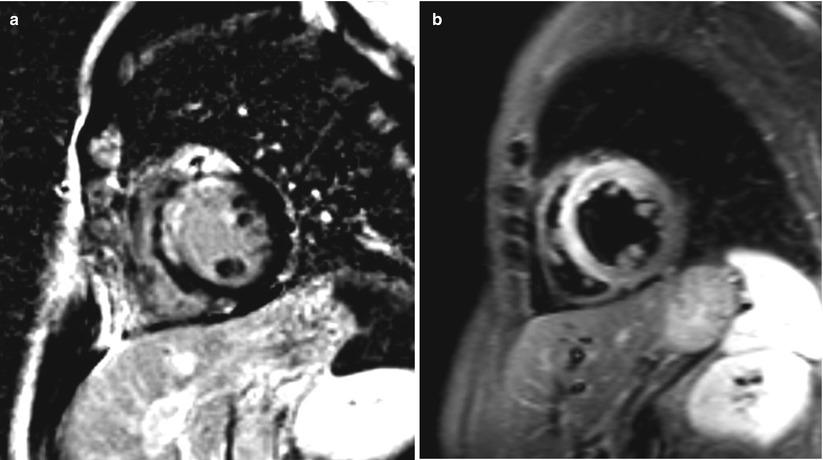
Fig. 22.5
Myocardial infarction and short tau inversion recovery (STIR) image. (a) Gd-enhanced image shows strong enhancement in the anterior free wall and ventricular septum of the LV wall from myocardial infarction. (b) STIR image shows high signal intensity in the same area of the LV wall due to myocardial edema
Only gold members can continue reading. Log In or Register to continue
Stay updated, free articles. Join our Telegram channel

Full access? Get Clinical Tree


