Mitral Valve
Transesophageal echocardiography (TEE) is superior to the transthoracic approach for characterizing the anatomy and function of the mitral valve (MV). In certain cases, it would completely replace transthoracic echocardiography for this purpose, were it not for the small risk, patient discomfort, and higher cost in terms of both time and money.
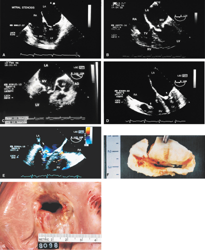
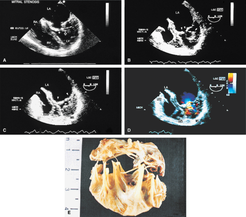
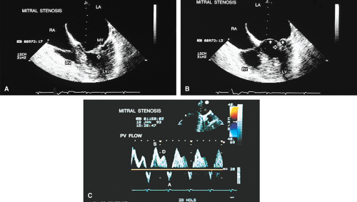
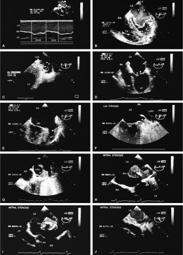
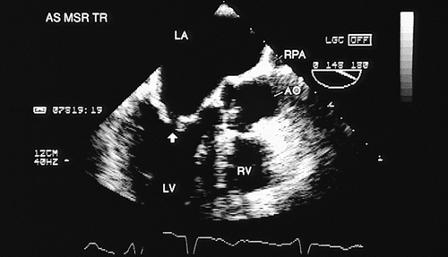
Transthoracic echocardiography is often adequate for the study of mitral stenosis. In patients with poor echocardiographic windows, or in whom TEE is performed for other reasons, the cause and severity of mitral stenosis are almost always revealed by TEE. Mitral stenosis produces clearly visible diastolic doming of the MV. This doming is the result of fusion of the leaflet commissures with relatively greater mobility of the remainder of the leaflets. In adults with mitral stenosis, the valve is usually thickened and calcified. Conventional Doppler examination allows the mean pressure gradient and the valve area to be calculated, the latter by the pressure half-time technique, which can be effectively performed using TEE. This method makes use of the fact that left atrial pressure decays more slowly when there is obstruction to emptying and makes use of the fact that pressure gradient is proportional to the square of the velocity. The empirical equation derived for mitral valve area (MVA) is
MVA (cm2) = 220/P1/2
P1/2 is the pressure half-time and 220 is an empirically derived constant. The P1/2 can be determined from the Doppler plot of velocity versus time as the time from peak velocity to the time when the velocity decays to (0.7 × peak velocity)1/2. Where the slope of the mitral inflow is bimodal, the calculation should be done with the lesser of the two slopes. The accuracy of the pressure half-time technique is limited in the setting of any obstruction to inflow, such as poor left ventricular compliance consequent to left ventricular hypertrophy or poor diastolic function. Also, the technique is less accurate in the setting of competitive flow into the left ventricle, such as that which occurs with aortic insufficiency.
Because of limitations imposed by the angle at which the MV can be imaged, planimetry of the valve from the transesophageal approach is not very accurate. Color Doppler flow examination in patients with severe mitral stenosis reveals a narrow jet and a region of prominent proximal diastolic flow acceleration in the left atrium (LA). TEE provides excellent imaging of the subvalvular apparatus, which can thicken and contribute to mitral outflow obstruction. Indeed, when the pressure half-time suggests stenosis more severe than that suggested by planimetry (from transthoracic echocardiography), the possibility of significant submitral obstruction should be considered.
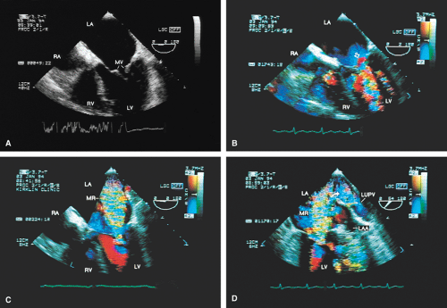
The severity of mitral regurgitation (MR) cannot be assessed by comparing jet area to left atrial area, as is done in transthoracic echocardiography, because the entire LA is not visualized. Instead, a semiquantitative grading system based on total jet area may be used. A jet area <4 cm2 indicates mild MR; an area 4 to 8 cm2 indicates moderate regurgitation; and an area >8 cm2 indicates severe regurgitation. The entire area of jet flow, including low-velocity flow, should be planimetered because the angle at which the flow is measured, which is nearly perpendicular at times, may cause the appearance of low velocity in a high velocity jet.
Sometimes the total jet area is misleading. In the case of eccentric jets (typically seen with mitral valve prolapse or flail mitral valve) or jets that strike a vegetation or course along a mitral leaflet or the atrial wall, momentum and jet energy are lost and less blood is entrained, and the jet size suggests less severe regurgitation than is actually the case. To determine the severity of MR, therefore, the entire study must be considered and the laminar flow signals moving with the turbulent jet taken into account when calculating the jet area. Visible extension of the regurgitant flow into the left atrial appendage (LAA) or any of the pulmonary veins indicates the presence of
severe regurgitation. In such cases, pulse Doppler interrogation of a pulmonary vein near its entrance into the LA demonstrates systolic flow reversal that may be aliased. This typically occurs in midsystole or late systole because the jet has to traverse the whole length of the LA before it reaches the pulmonary vein. It is important to interrogate all the pulmonary veins by Doppler because systolic flow reversal may be found in only one of them. Reduction in the height of the systolic wave without flow reversal may be seen with moderate regurgitation, but this is not a specific finding. It may also occur in patients with left ventricular dysfunction without MR.
severe regurgitation. In such cases, pulse Doppler interrogation of a pulmonary vein near its entrance into the LA demonstrates systolic flow reversal that may be aliased. This typically occurs in midsystole or late systole because the jet has to traverse the whole length of the LA before it reaches the pulmonary vein. It is important to interrogate all the pulmonary veins by Doppler because systolic flow reversal may be found in only one of them. Reduction in the height of the systolic wave without flow reversal may be seen with moderate regurgitation, but this is not a specific finding. It may also occur in patients with left ventricular dysfunction without MR.
The so-called “vena contracta,” the narrowest cross-section of the regurgitant jet as it crosses the MV, also offers an approach to assessing the severity of MR. A vena contracta <3 mm suggests mild regurgitation, a vena contracta >6 mm suggests severe regurgitation and those between 3 and 6 mm are indeterminant.
Prominent proximal flow acceleration also alerts the echocardiographer to the presence of significant MR in patients with small eccentric regurgitant jets. The proximal isovelocity surface area (PISA) technique makes use of this proximal flow acceleration to quantify the severity of MR. The continuity equation of fluid mechanics tells us that in a steady, incompressible flow the mass flow rate is constant throughout the flow field. As flow accelerates toward the mitral regurgitant orifice (MRO), aliasing occurs at the position in the flow field at which the Nyquist limit is reached (there is a shift from blue to red or vice versa). Thus, the velocity along the approximately hemispheric surface at the red–blue interface is known. The diameter can be measured and the surface area calculated. The flow across the isovelocity surface can be calculated as the product of the surface area and the velocity at the Nyquist limit. The flow across the regurgitant orifice must be the same (continuity equation). Hence,
Flow rate = Aliasing velocity × 2 π r2 = ERO × Vjet
where ERO is the effective regurgitant orifice area and Vjet is the peak mitral regurgitant velocity obtained by continuous wave Doppler. The ERO can then be calculated as
ERO = Flow rate/Vjet
and the regurgitant volume can be calculated as
Regurgitant volume = ERO × TVI
where TVI is the time velocity integral of the mitral regurgitant jet. Measurement is facilitated by lowering the Nyquist limit to maximize the radius of the aliasing isovelocity surface. ERO (mm2) <20 represents mild MR (1+); 20–29 represents moderate MR (2+); 30–39 represents moderately severe MR (3+); and >40 suggests severe MR.
The PISA technique, although relatively easy to use, is limited by the many assumptions (mostly incorrect) necessary to use it. For instance, it assumes that the three-dimensional region is a hemisphere and that the maximum flow across the ERO is the same as the flow across the aliasing region. It is also assumed that the ERO is at the center of the aliasing surface.
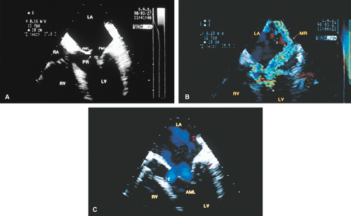
Prolapse of the MV is the most common cause of MR in the United States and may be well seen by TEE. The most convincing evidence of prolapse is when it is localized. The picture of the entire leaflet bulging into the LA may be an artifact produced by the imaging plane. Features that are particularly convincing for this diagnosis include localized prolapse of a portion of a leaflet or leaflets into the LA, producing the appearance of buckling. Thickening of the leaflets suggesting myxomatous degeneration of the MV is supportive of this diagnosis. When the leaflets are thin and produce a smooth concavity in the direction of the apex of the left ventricle, even when the leaflets bow behind the plane of the mitral annulus, the likelihood is of a normal variant rather than mitral valve prolapse (MVP). Multiple views help make the distinction. It is necessary to distinguish between the redundancy that is sometimes seen in these valves and vegetation. TEE has been used in the identification of individual scallop (posterior mitral leaflet) or segment (anterior mitral leaflet) prolapse. However, the methodology used is operator dependent and not always reliable. In general, the middle portions of both posterior (P2) and anterior (A2) leaflets are visualized in the apical four-chamber view and hence A2 and/or P2 prolapse can be diagnosed. Similarly, the lateral portions of both leaflets tend to be visualized in the five-chamber plane, permitting diagnosis of P1 and/or A1 prolapse. Probe advancement from the four-chamber view transects medial portions of mitral leaflets, which facilitates the identification of P3 and/or A3 prolapse.
Chordal rupture results in severe mitral prolapse and noncoaptation of the mitral leaflets. The ruptured chordae can be identified as linear echoes fluttering in the LA. These linear echoes must not be confused with Lambl’s excrescences, which are small linear filaments that may normally be present on the MV or any of the other valves. These filaments are best seen on transesophageal echocardiography. Rupture of primary chordae causes severe MR, whereas rupture of secondary or tertiary chordae may cause less severe insufficiency.
TEE is far more sensitive in identifying vegetations than transthoracic echocardiography. For this reason, in the appropriate clinical setting, a negative transthoracic echocardiogram should lead to TEE. Valve thickenings are most convincingly diagnosed as vegetations when they are mobile or oscillating. They are most often seen on the proximal (low velocity) side of the valve, but they can be seen anywhere. The presence of vegetation on one valve should prompt a search for vegetations on other valves. Serial echoes may be needed for the diagnosis, because vegetations may grow over time. The presence of calcification may make the vegetation appear larger.
Abscesses usually present as echo-free spaces, although echolucency may be diminished by the presence of thick pus in the abscess. Abscesses can rupture and produce fistulous connections to any structure. A common location for an abscess is in the annulus fibrosus, located at the junction of the mitral and aortic valves (mitral–aortic intervalvular fibrosa). The MV may become aneurysmal and perforate, as may the fibrosa between the mitral and aortic valves. These aneurysms may become very large. Color-flow Doppler can demonstrate the to-and-fro flow of blood into and out of the aneurysm. Infection is the most common cause of such aneurysms, but they may also be caused by trauma, particularly surgical trauma.
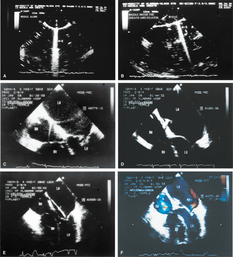
TEE is useful in the performance of percutaneous mitral valvuloplasty. A scoring system has been devised to help decide whether the procedure is feasible. Pliability, thickening, calcification, and subvalvular thickening are each scored on a scale from 0 to 4. A total score <8 suggests that the valve structure is very suitable for the procedure. TEE can also be used to ensure that there are no clots in the LA (including the LAA) because the presence of a clot contraindicates the percutaneous mitral valvuloplasty. TEE can be used as a guide when performing the procedure, specifically, the needle puncture of the interatrial septum. The septum can be seen to “pucker” when it is touched by the needle. In addition, the tip of the needle produces a prominent reverberation that helps to identify it. A rapid assessment for the presence of MR can be made following the procedure. The presence and size of atrial septal defects (ASD) produced by the procedure can be assessed, although these usually close over time.
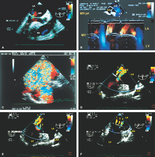 FIGURE 2.13. Mitral regurgitation. A. A small jet of mitral regurgitation (MR) consistent with mild MR. B. Color M-mode examination of another patient shows MR. In the second cardiac cycle, two MR jets are seen. C.
Get Clinical Tree app for offline access
Stay updated, free articles. Join our Telegram channel
Full access? Get Clinical Tree


|
