Minimally Invasive and Robotic Approaches to Mitral Valve Surgery
W. Randolph Chitwood Jr.
Introduction
Over the past 15 years, minimally invasive cardiac valve surgery has gained worldwide traction as a standard of care for many patients and surgeons. Early reports suggested that alternative incisions and minimally invasive approaches to replace and repair mitral valves were safe and efficacious. Large series as well as several meta-analyses have confirmed that minimally invasive mitral valve surgery (MIMVS) is appropriate for many patients. Also, robotic mitral valve repair series at dedicated referral programs have shown outcomes similar to operations done either through a sternotomy or a minimally invasive incision. The economic costs often have been challenged; however, high-volume Mayo and Cleveland Clinic robotic mitral valve repair programs have shown parity with other incisional approaches.
Patients should have the indications for mitral valve repair surgery as outlined in either the 2014 ACC/AHA (United States) or 2012 ESC/EACTS (European) Guidelines. The minithoracotomy incision, with or without assisted vision or robotics, is indicated for both primary and reoperative mitral valve surgery in patients with no or few comorbidities. Moreover, combined mitral and tricuspid valve operations can be performed safely through a mini-thoracotomy. Nevertheless, some surgeons prefer to use a hemisternotomy for MIMVS. Patients requiring either concomitant multivessel coronary revascularization, an aortic valve replacement, or have a significantly dilated ascending aorta should have a traditional sternotomy operation. General contraindications to the mini-thoracotomy approach are listed in Table 18.1.
TABLE 18.1 Contraindications: Minimally Invasive Mitral Valve Surgery | ||
|---|---|---|
|
Informed consent for a minimally invasive or robotic mitral repair should include the choice of a traditional sternotomy operation as well as the possibility of conversion to a sternotomy for safety or to achieve the operative goal. Either an excellent transthoracic echocardiographic (TTE) or transesophageal echocardiographic (TEE) study should be done to determine operative necessity and to guide the operative plan. In select patients computed tomographic (CT) images should be obtained to determine the status of the peripheral vasculature and aorta as well as define any noncardiac thoracic pathology. Patients at risk for coronary artery disease either should have coronary angiography or a CT angiogram. After anesthesia preparations, a comprehensive 2D and 3D TEE study should be done in the operating room to render the necessary planning information listed in Table 18.2.
At our center all minimally invasive, robotic, and traditional mitral repairs are considered, planned, and directed from intraoperative TEE studies. To determine an appropriate annuloplasty ring or band size, we have developed a TEE-based nomogram, which has been validated with actual leaflet measurements and commercial ring sizers (Table 18.3). Because of accentuated leaflet curvilinearity associated with extreme billowing in Barlow’s pathology, TEE can underestimate actual leaflet lengths. Thus, in these patients direct linear measurements of each leaflet segment should be made after cardiac arrest.
Long anterior leaflets (>30 mm A2), especially in the presence of a high (long) posterior leaflet (>20 mm), a narrow aortomitral plane angle (<120 degrees), or a thickened outflow interventricular septum, may portend the development of postrepair systolic
anterior motion of the anterior leaflet. This can create a major hemodynamic problem when weaning from cardiopulmonary bypass (CPB). Preventative structural repair measures should include: (1) Implantation of a large ring/band, (2) reduction of the posterior leaflet height to 15 mm or less, and (3) achievement of an optimal leaflet coaptation surface (8 to 10 mm). In the arrested heart the saline ventricular pressure test, done after the final repair, is helpful to determine the degree of leaflet coaptation level and symmetry.
anterior motion of the anterior leaflet. This can create a major hemodynamic problem when weaning from cardiopulmonary bypass (CPB). Preventative structural repair measures should include: (1) Implantation of a large ring/band, (2) reduction of the posterior leaflet height to 15 mm or less, and (3) achievement of an optimal leaflet coaptation surface (8 to 10 mm). In the arrested heart the saline ventricular pressure test, done after the final repair, is helpful to determine the degree of leaflet coaptation level and symmetry.
TABLE 18.2 Transesophageal Echocardiographic Planning Data | |
|---|---|
|
TABLE 18.3 Echo-Based Annuloplasty Banda Sizing | ||||||||||||||||
|---|---|---|---|---|---|---|---|---|---|---|---|---|---|---|---|---|
| ||||||||||||||||
Patient Positioning
In general preoperative patient positioning, anesthesia management, echocardiographic evaluation with repair planning, the operative set-up, and perfusion techniques are the same for all of our robotic and nonrobotic MIMVS. For both approaches the patient should be positioned with the right chest elevated by 30 degrees on a commercial lift or a cloth roll. The right arm should be distracted laterally and supported safely inferior to the posterior axillary line. The right axillary area should be exposed to insert the transthoracic aortic cross-clamp. Standard skin preparation and draping should provide wide exposure to the right chest, sternum, and both groins.
Anesthesia Management
In most operations our anesthesiologists prepare patients as shown in Figure 18.1. These preparations include placing the following:
Either a double-lumen endotracheal tube or a right endobronchial blocker
A right radial arterial blood pressure monitoring catheter
Posterior-anteriorly placed Zoll defibrillator pads
A right internal jugular introducer for drug infusions and Swan–Ganz pulmonary artery catheter insertion
A thin-walled (15-Fr or 17-Fr) Bio-Medicus (Medtronic, Inc., St. Paul, MN) right internal jugular venous drainage cannula (double-puncture method)
A 3D transesophageal echocardiographic probe
 Figure 18.1 Anesthesia preparation for videoscopic and robotic mitral valve surgery. TEE probe, transesophageal echocardiography; ET tube, double lumen endotracheal tube; SVC, superior vena cava; SG, Swan–Ganz. |
Working Incision
Today, most minimally invasive and robotic mitral valve operations are performed through a right-side fourth intercostal mini-thoracotomy. The choices for visualization include a direct view through the incision, 2D endoscopic, or 3D robotic. Recently 3-D non-robotic endoscopes have been developed. The size of the working incision usually relates to both the visualization and operative method chosen by the surgeon. For both direct vision and 2D endoscopic MIMVS, a 4- to 5-cm mini-thoracotomy is made in the fourth intercostal space at the anterior axillary line. Smaller port-access incisions (2 to 3 cm) are made in the same area for robotic operations. We place a flexible Alexis soft tissue wound protector (Applied Medical, Inc., Rancho Santa Margarita, Calif.) in preference to using a rib-spreading retractor. We have found that this minimizes postoperative pain and provides good working-incision exposure for either direct vision, endoscopic, or robotic MIMVS.
Cardiopulmonary Perfusion
All perfusion cannulas are placed under echocardiographic guidance using the Seldinger guidewire technique. The right femoral artery is cannulated with either a 17-Fr or 19-Fr Bio-Medicus cannula through a 2-cm oblique groin incision. For inferior vena caval drainage, either a 22-Fr (single stage) or a 23-Fr/25-Fr (dual stage) RAP femoral venous cannula (Estech, San Ramon, CA) is passed into the right atrium (Fig. 18.2). Vacuum-assisted venous drainage is used in all of these operations. Intrathoracic carbon dioxide is insufflated throughout each operation to minimize the amount of intracardiac air entrapment. To monitor adequate limb perfusion, during CPB, oxygen saturation levels are monitored continuously in each leg using the Invos system (Somanetics Inc., Troy, MI). If a significant arterial saturation decrease occurs in the cannulated leg during CPB, we place a distal superficial femoral artery 5-Fr catheter and connect it to the arterial perfusion circuit. To date, we have had no problems with residual leg ischemia.
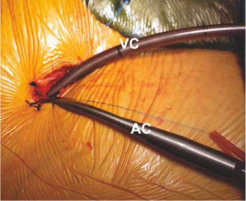 Figure 18.2 Arterial and venous perfusion cannulas. Through a 2-cm right groin incision, 4-0 polypropylene purse-string sutures are placed along the anterior adventitial surface of the common femoral artery and vein. Using the Seldinger guidewire technique and under echocardiographic guidance, either a 22-Fr (single stage) or a 23-Fr/25-Fr (dual stage) RAP femoral venous cannula (Estech, San Ramon, CA) (VC) is passed into the right atrium. Similarly a 17-Fr or 19-Fr Bio-Medicus (Medtronic, Inc., St Paul, MN) arterial cannula (AC) is passed into the common iliac artery. |
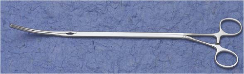 Figure 18.3 Transthoracic aortic clamp. |
Aortic Occlusion
For aortic occlusion, we use a transthoracic cross-clamp (Scanlan International, St. Paul, MN) as it has been proven to be safe, reliable, economic, and simple to apply (Fig. 18.3). The posterior clamp tine should be passed through the transverse sinus under either direct or videoscopic vision. The anterior tine is positioned across the aorta until it reaches the main pulmonary artery (Fig. 18.4). Care must be taken not to injure the right pulmonary artery, left atrial appendage, left main coronary artery, or aorta.
Some surgeons prefer to use endoaortic balloon occlusion. This technique has a steeper learning curve than using the clamp. The balloon position must be precise and remain stable in the ascending aorta. There is a potential for either innominate artery occlusion or intraventricular displacement. Therefore, TEE monitoring of balloon position throughout the operation is mandatory. Also, balloon catheter introduction through the femoral arterial cannula can limit perfusion flow. In this circumstance the endoballoon catheter should be inserted through the other femoral artery. Despite these concerns, this method can provide effective aortic occlusion, a route for delivering antegrade cardioplegia, and an air vent without needing a separate aortic root cannula.
Myocardial Protection
As mentioned, we have always used the transthoracic aortic clamp method for both minimally invasive and robot-assisted mitral valve surgery. A pledgeted diamond-shaped 4-0 PTFE purse-string suture is placed in the ascending aorta and proximal to the fatty fold of Rindfleisch. For antegrade cardioplegia administration, a long cardioplegia-vent catheter (Medtronic, Inc., St Paul, MN) is inserted through the purse strung suture, secured and then passed either through a chest wall trocar or the working incision. This catheter is inserted either under robotic, endoscopic, or direct vision (Fig. 18.5).
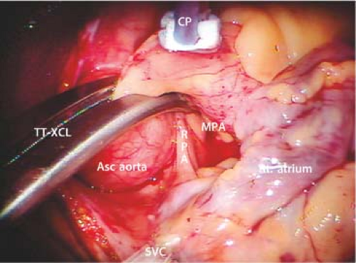 Figure 18.4 Transthoracic aortic clamp—positioned through the transverse sinus. TT-XCL, transthoracic cross-clamp; Asc aorta, ascending aorta; MPA, main pulmonary artery; RPA, right pulmonary artery; CP, cardioplegia/vent catheter; SVC, superior vena cava; Rt. atrium, right atrium. Note that the clamp is positioned cephalad to the pericardial–SVC junction. |
 Figure 18.5 Cardioplegia/vent catheter insertion. The cardioplegia/vent catheter is placed in the ascending aorta through a 4-0 pledgeted PTFE “purse-string” suture just proximal to the fatty aortic fold. |
Recently, our group switched from blood cardioplegia to Custodiol–Bretschneider’s HTK solution (Franz Köhler Chemie Bensheim GMBH, Germany) as it provides much longer myocardial protection without requiring frequent reinfusions. For maximal myocardial protection, we combine this antegrade cardioplegia with a systemic blood inflow temperature of 28°C. If blood cardioplegia is used, repeat administrations should be delivered at 15- to 30-minute intervals. Multiple cardioplegia infusions, requiring atrial retractor relaxation and repositioning, can entrain air into the aortic root.
For patients having had a previous sternotomy, we cool the patient systemically to 26°C and induce ventricular fibrillation by rapid pacing with a custom Swan–Ganz catheter. In patients with mild aortic insufficiency, additional intracardiac suction can be combined with dropping perfusion flow briefly for difficult suture placement.
Cardiac Exposure
After going on CPB, the pericardium is opened longitudinally approximately 3 cm anterior to the phrenic nerve, using either long-shafted endoscopic or robotic instruments. Two to three well-spaced pericardial retraction sutures are placed along the inferior (dorsal) pericardial edge (Fig. 18.6). By passing the needle through the end loop, only one suture is withdrawn through the chest wall using a crochet hook instrument. Care should be taken not to stretch or injure the phrenic nerve. The anterior (ventral) pericardial edge is then suspended with two sutures that are brought through the working incision.
2D Endoscopic MIMVS
After completing the above maneuvers and establishing cardiac arrest, we pass a 5-mm high-definition 2D endoscope (KARL STORZ GmbH & Co. KG, Tuttlingen, Germany) through a third intercostal space trocar and attach it to a hand-positioned holder (Fig. 18.7). Alternatively, a larger incision can be made for direct viewing of the mitral valve operative field. The left atriotomy is made just medial to the right superior and inferior pulmonary veins.
A transthoracic atrial retractor arm (Atrial Lift System, ESTECH, San Ramon, CA) is passed through the chest wall, just medial to the sternum in the fourth interspace, and coupled to the appropriate size blade. This arm is then attached to a table-mounted support that facilitates lifting of the interatrial septum. After adjusting the retractor for optimal exposure, the mitral valve repair or replacement is done using long-shafted instruments. For annuloplasty band/ring and valve prosthesis suture organization, we use Gabbay–Frater suture guides (Teleflex Medical, Research Triangle, NC), placed externally around the working incision. Long-shafted instruments are used for
endoscopic and direct vision MIMVS and provide good rotational ergonomics, but remain without the advantage of full articulation.
endoscopic and direct vision MIMVS and provide good rotational ergonomics, but remain without the advantage of full articulation.
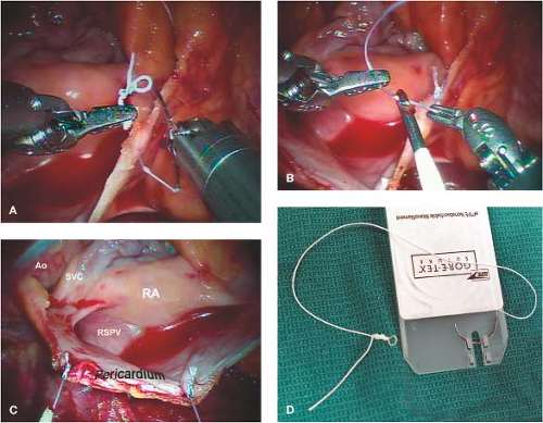 Figure 18.6 Suture “loops” for pericardial retraction and left atrial closure. Tiny PTFE loops are created from or 2-0 Ti-cron sutures. A: After passing the needle through the pericardial edge, it is threaded through the loop. B: Thereafter, the suture is withdrawn through the chest wall using a crochet hook instrument. C: Two or three sutures are used to distract the pericardial edge (pericardium) laterally, exposing the right superior pulmonary vein (RSPV), aorta (Ao), right atrium (RA), and superior vena cava (SVC). D: For left atrial closure, we use a 3-0 Gore-Tex suture loop on a PH-21 needle (W. L. Gore & Associates, Inc., Flagstaff, Arizona). |
3D Robot-assisted MIMVS
Robot-assisted cardiac surgery should be called surgical telemanipulation as the term “robot” means autonomous. The da Vinci surgical system (Intuitive Surgical, Inc., Sunnyvale, CA) merely provides access with superb visualization and enhanced ergonomics, which allows surgeons to perform complex operations through small port-like incisions. When using long hand-held instruments, the working incision becomes a fulcrum that can limit accurate suture placement and tissue manipulation. The accuracy achieved with da Vinci instruments relates to wide freedom of motion at the operative plane. The surgeon always has control of instruments by telemanipulation, as if they were activated directly by his/her hands.
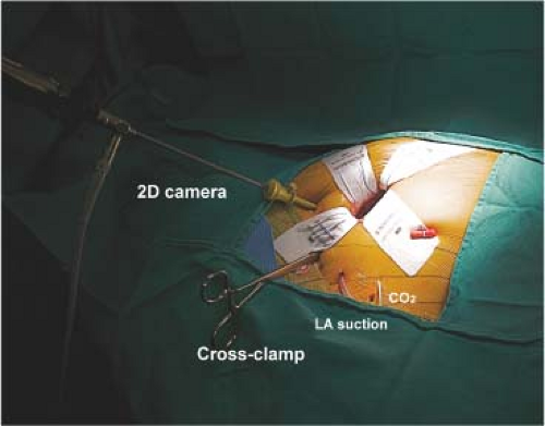 Figure 18.7 Videoscopic set-up. For nonrobotic mitral surgery a 5-mm Storz videoscopic camera (2D vision) is placed via a trocar through the 3rd intercostal space and attached to a fixed holder. The transthoracic cross clamp (TT-XCL) is shown placed through the fourth intercostal space. Non-rib–spreading soft tissue retractor is through the 4th intercostal space working incision. An intrathoracic carbon dioxide insufflation catheter and left atrial sump are shown. |
The Robotic Cardiac Team
An organized team is paramount for a successful robotic cardiac surgical program. This includes anesthesiologists, surgeons, tableside assistants, scrub personnel, circulating nurses, and perfusionists. Team and procedure training at an experienced robotic valve center has been very important when launching successful programs. Surgeons should be accomplished at mitral and tricuspid repairs before beginning this new trek. Before applying robotic methods, the team should master needed peripheral perfusion techniques as well as operating through minimally invasive incisions. After team comfort has been achieved, progression to robotic mitral valve operations is reasonable and gratifying. It is important to remember that robotic instruments are only access tools and not the operation.
Stay updated, free articles. Join our Telegram channel

Full access? Get Clinical Tree


