and Eric J. Feldmann2
(1)
Department of Medicine and Radiology, Stony Brook University Hospital, Stony Brook, NY, USA
(2)
Department of Radiology, Stony Brook University Hospital, Stony Brook, NY, USA
Recent dramatic technological advances in computed tomography (CT) technology allow routine performance of cardiac computed tomography angiography (CCTA) with excellent image quality at modest effective radiation doses (E). Improved z-axis coverage, utilizing scanners with 64, 128, 256, and 320 z-axis detector-rows, decreases “slab artifact,” improves contrast opacification, and allows shorter breath holds – thus further decreasing cardiac motion artifacts and improving overall image quality. Improved “true” hardware-dependent temporal resolution, now at roughly 100–175 ms with single source and 75 ms with dual source scanners, decreases artifacts from coronary artery motion. Improved detector technology now yields a maximal spatial resolution on the order of 18.2 line pairs/cm.
CCTA has truly transformed from the exotic to the routine in the last decade. This chapter focuses on the underlying principles pivotal in this transformation: basic CCTA physics, patient preparation, image acquisition, imaging techniques/protocols, postprocessing techniques, and artifacts/artifact reduction.
1.1 CT Scanner Basics
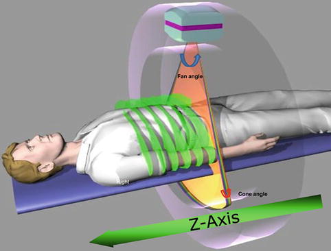
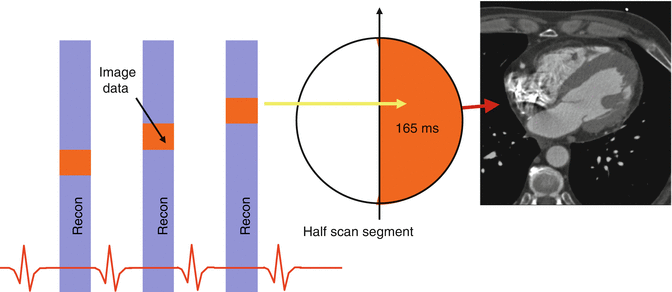
The main components of a CT scanner are the gantry (containing the detector row/photon source unit), table, and the computer software/hardware to process the raw data. The gantry is donut-shaped and contains a photon source opposite a panel of detectors that both rotate around the patient/table in the x–y plane as a fixed unit opposite each other (Fig. 1.1). Dual source scanners have two such units at roughly 90° offset in the x–y plane. Typically the speed of this rotation ranges from 0.2 to 0.35 s/rev in most modern scanners and is the most important determinant of true temporal resolution in CT, which is calculated as half the time for a full rotation plus an angular correction for the fan beam geometry (Fig. 1.2). This yields temporal resolutions of roughly 100–175 ms with single source and 75 ms with dual source scanners. The source detector unit is continuously moving throughout the entire exam; however the delivery of photons can be turned off and on quite rapidly, as well as the mA (amount of photons) adjusted (e.g., automatic tube current modulation and EKG gated tube current modulation). Although slower, the kVp can also be changed to different energies on dual energy scanners.


Fig. 1.1
Gantry with radiation tube (photon source) and detector rows, also depicting cone beam angle and fan angle (Picture Courtesy of Michael Poon MD)

Fig. 1.2
Reconstruction of an image using data from half gantry rotation. To create an axial image, we only require an approximate data from half of the scan rotation plus fan angle. This then gives us a an approximate temporal resolution of 165 ms based on a gantry rotation of 330 ms. The orange boxes are image data reconstructed at the same phase of the cardiac cycle (Picture Courtesy of Michael Poon MD)
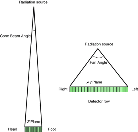
Similar to MRI, when describing a CT scanner, it is customary to consider the long-axis of the table the z-axis, and the short axis the x–y plane. The photon source is a point source, in that it creates an Elliptical cone of photons from a focal spot. The angle of the elliptical cone in the x–y plane is called fan angle, and in the z-plane is called cone angle. Fan angle is typically around 40–50° and determines the maximum x–y plane of image reconstruction or scan field of view (SFOV) of the study. Manufacturers typically allow you to choose SFOV (sometimes called calibrated field of view) for a scan. Ranges vary from 18 to 50 cm. For CCTA, typically 320–400 mm is used as this covers the majority of patient x–y axis size. Cone angle is very small with 64 detector row CT scanners, but become substantially larger with the use of 256 × 0.625mm or 320 × 0.5 mm collimation. Cone angle and the number of detectors in the z-axis determine the amount of z-axis coverage acquired with one gantry rotation (Fig. 1.3) [1].


Fig. 1.3
Simplified representation of cone beam angle and fan angle. Typically there are several hundred detectors which are concave towards the radiation source. For a 64-detector row scanner, cone and fan angles are usually around 2.4 and 60 degrees, respectively
There are a few scanning techniques available on current CT scanners. A scout tomogram is obtained without rotation of the gantry, just with table movement and a few detector rows. The image has an appearance grossly similar to a standard AP, PA, or lateral radiograph. It is performed on all exams to plot the z-axis and x–y plane coverage needed. Once the gantry is spinning, two acquisition methods are available, depending on whether or not the table is moving during scanning. If the table is moving during image acquisition then it is called “helical” or “spiral” acquisition. If the table is not moving during imaging acquisition then it is called “step and shoot,” “sequential,” “axial,” or “volume scanning.” Currently (except for in dual-source scanners), the prospectively triggered “step and shoot” acquisition is preferred in most routine applications of CCTA [2].
1.2 Resolution
1.2.1 Temporal Resolution
Temporal resolution is simply defined as the shortest acquisition time necessary to reconstruct an image. It is analogous to the shutter speed of your camera. It can be thought of as having hardware (gantry rotation speed in rev/msec) and software (i.e., multisegment reconstruction, half scan reconstruction) components. Further discussion on its effect on image quality is elaborated in the coronary motion artifact section.
1.2.2 Spatial Resolution (High Contrast Resolution)
The ability to discern the edges between adjacent small objects that differ greatly in attenuation. It is typically thought of as intrinsic to a scanner and defined by a bar phantom (in line pairs per centimeter). Although, there are also postprocessing/reconstruction methods that may increase apparent spatial resolution (sharper kernel, overlapping slices, etc.). It is defined in both in the x–y and z planes. It corresponds to typical voxel/pixel values of around 0.3–0.6 mm on today’s scanners. Spatial resolution is crucial in coronary CTA because the contrast filled coronary artery lumen (250–500 HU) demonstrates high contrast with the background of epicardial fat (−30 to −100 HU).
1.2.3 Contrast Resolution (Low Contrast Resolution)
The ability to distinguish between objects of similar attenuation; for example a 10 HU liver lesion in the background of 50 HU liver parenchyma. It is typically dependent on image signal to noise ratio and is quantitatively defined by a low-contrast phantom for a given technique/scanner. For enhancing structures on contrast enhanced exams, it may be improved utilizing lower kV (80–100 kVp) technique. Typically, low contrast resolution is not as important in coronary CTA as spatial resolution because the contrast filled coronary artery lumen (250–500 HU) demonstrates high contrast with the background of epicardial fat (−30 to −100 HU). It is more relevant in CT myocardial perfusion imaging.
1.3 Basic Principles of CCTA Image Acquisition
CCTA fundamentally differs from most routine CTs in that on top of it being respiratory gated (utilizing a breath hold) – it is EKG gated. EKG gating simply means synchronizing CT data acquisition to a specific cardiac “phase.” Phase is defined as a percentage of the R-R interval, so that for a person with a heart rate of 60 bpm 30 % would be near end systole and 75 % would be near end diastole. Although it is arbitrary, it is a more specific nomenclature than the traditional phases of the cardiac cycle taught in physiology. There are two modes of ECG synchronized acquisition:
1.
Prospective ECG triggering
2.
Retrospective ECG gating
1.3.1 Prospective ECG Triggering with Step and Shoot Technique
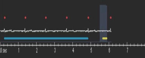
This is a technique where the previous few heart beat R-R intervals are used to predict the expected future R-R interval. Typically this is utilized with step and shoot scanning. The data are only collected at a predefined phase (typically 750 ms at 60 bpm), and for a predefined time interval (minimum 350 ms at 60 bpm), which is determined by a user defined delay before acquisition (Fig. 1.4). Depending on the scanner z-axis collimation per rotation, the step and shoot will continue until the scanning is completed in the z-axis. For example, if the region of interest (heart) being scanned is 16 cm, for a 64 detector-row single source scanner with 0.625 mm detectors (4 cm coverage during a single gantry rotation), it will take 4 scans or “steps” to cover the z-axis of the entire heart (Fig. 1.5). Vis-a-vis a 320 detector-row scanner with a maximum of 16 cm z-axis coverage per rotation will acquire the entire z-axis of the heart in one scan (Fig. 1.6).
 < div class='tao-gold-member'>


Only gold members can continue reading. Log In or Register to continue
Stay updated, free articles. Join our Telegram channel

Full access? Get Clinical Tree


