Intracranial Vessels
Hans Henkes
Jörg Reinartz
Elina Miloslavski
Steven Lowens
Dietmar Küuhne
Catheter-based therapy of neurovascular disorders started in the early 1960s1 but remained in a rudimentary state until the mid-1980s. Since then the ideas and collaborative efforts of individual physicians and engineers have helped create a completely new technology within <20 years.
The clinical practice of neuroendovascular therapy is today still far from being a standardized process. The indications, concepts and strategies of treatment, techniques, and results still vary widely from center to center and even from one physician to another. This situation is also reflected in this chapter, which summarizes some of the personal experiences of the two senior authors (HH, DK) who have performed or supervised several thousand neuroendovascular procedures. The reader will not find a universal “cookbook” on how to perform neurovascular interventions, but rather our perspective and our representation of the field. Some of our statements are based on scientifically documented evidence, but all of them are justified by our clinical practice, even if some may appear more or less speculative and are only confirmed by our personal observations.
Training Requirements and Quality Assurance
Currently, there are no formal criteria or guidelines regarding facility and training requirements, just as there are no quality standards for neurovascular interventions, although several guidelines regarding the performance of specific neurovascular procedures have been advanced.2 The question of who should be entitled to carry out neuroendovascular procedures is still unanswered. The two major regulatory mechanisms (the medicolegal system and reimbursement policies) and the efforts of professional societies are only beginning to have an impact. For example, the initiatives of the European Society of Neuroradiology (ESNR) and of the American Society of Neuroradiology (ASNR) are still in their early stages.3,4
During the past 15 to 20 years, a number of centers dedicated to neurovascular interventions have been established worldwide. No fewer than 200 intracranial procedures per year should be performed at centers providing formal training, and both the technical success and the clinical outcome of these procedures, including complications, should be documented in standard protocols to permit quality control and assurance.
The technical results and clinical outcome of neuroendovascular procedures depend on a number of factors, including the patient selection criteria, technical equipment, and quality of instrumentation. Most important are, however, the experience and technical skills of the operator and the competence of the entire team.5 Critical features that are probably beyond the realm of any formal criteria are whether the operator has the cognitive and intellectual skills to analyze clinical and anatomic case scenarios, the abilities to draw proper conclusions, and the ability to implement concepts of endovascular treatments. Given the frequently mutilating or even fatal outcomes of complications from neuroendovascular treatments, physicians performing these procedures should have undergone a minimum of 2 years of full-time supervised training in a dedicated high-volume center. One should keep in mind that this is still a fraction of what is required until a neurosurgeon is able and allowed to operate on an intracranial aneurysm.
There is a broad consensus that emergency endovascular procedures such as selective intra-arterial thrombolysis or coil occlusion of ruptured aneurysms should be offered in neuroradiology departments servicing neurosurgical and neurological clinics. An unresolved issue is how more specialized
treatments, such as embolization of brain arteriovenous malformations (AVMs) without acute intracranial hemorrhage, and infrequent procedures, such as stent percutaneous transluminal angioplasty (stent PTA) of intracranial atherosclerotic stenoses or the management of newborns with vein of Galen malformations, should be performed. One might expect that clinical results are better in high-volume centers and in those that can refer to their own historical data.6
treatments, such as embolization of brain arteriovenous malformations (AVMs) without acute intracranial hemorrhage, and infrequent procedures, such as stent percutaneous transluminal angioplasty (stent PTA) of intracranial atherosclerotic stenoses or the management of newborns with vein of Galen malformations, should be performed. One might expect that clinical results are better in high-volume centers and in those that can refer to their own historical data.6
General Considerations
Most of the endovascular procedures described in this chapter can be standardized up to a certain degree, but some personal aspects and preferences will always remain.
Technical standards facilitate a procedure and make incidental mistakes or errors less likely. These standards may, within limits, apply to individuals and institutions and can later form the basis of our “common sense.”
The use of high-resolution digital subtraction angiography (DSA) instead of film-based angiographic technology, manufactured microcatheters instead of self-assembled ones, and detachable coils instead of balloons in the treatment of aneurysms are just a few examples of established technical standards.
The duration of a procedure represents a critical quality factor. Every neuroendovascular treatment should be finished as quickly as reasonably possible, and any voluntary delay should be avoided. Adherence to the principle of simplicity helps to avoid complications. Although the simultaneous use of several microcatheters, balloons, and wires is sometimes required in order to treat challenging lesions, in most cases the use of just a single microcatheter is sufficient for successful treatment. Thorough familiarity with the radiographic equipment, the ability to generate and to interpret high-quality diagnostic angiograms,7 and the ability to properly handle the endovascular devices employed are preconditions for successful neurovascular interventions. It is important to realize that the fortunate supply of constantly new equipment for neuroendovascular interventions always opens a new learning curve, which only in retrospect can be justified by improved technical and clinical outcomes. The conservative expert use of well-selected and familiar catheters, wires, coils, and embolic agents is probably superior to the habit of immediately pursuing each and every unproven new trend or fashion. The conservative selection of equipment appears to be particularly important during the learning phase of less experienced operators. The meticulous evaluation of clinical and technical results is the best source of knowledge and the most accomplished means of validating and establishing new standards. The teaching value and intellectual yield of follow-up angiograms are frequently more important for education and sharpening cognitive skills than the technical performance of the underlying treatment. The rigorous analysis of complications is the only way to avoid their repetition.
Preinterventional Evaluation of Patients
Not all patients referred to our centers are really suitable for endovascular treatment, but sometimes this only becomes evident in retrospect. Meticulous documentation is required in order to understand as much as possible about a patient, his disease, his complete medical history, and his expectations. Speaking to the patient and his family is the key. The patient’s file has to include his complete neurological status, comprising handedness, his history of stroke and epilepsy, and also that of his ancestors. Known diseases (family and personal), medication, previous imaging findings, and previous procedures of all kinds (surgery, irradiation, and endovascular) are actively queried. It is not sufficient to just collect what a patient spontaneously reports. Images from previous examinations are sometimes decisive and should be available. The results of laboratory examinations such as serum electrolytes, creatinine, thyroid gland hormones, and standard coagulation tests are updated if necessary. Before undergoing a procedure, the patient is examined by a specialized neurologist or neurosurgeon; examination by a neuroanesthesiologist is very helpful. It is important to emphasize that everything not clearly documented in the patient’s file is literally nonexistent, especially from a legal standpoint.
Patient Consent for Neuroendovascular Treatment
Informed consent is required in all elective procedures, but is sometimes difficult to obtain.4,8 Whereas in emergency situations the physician does whatever he assumes would be the best for the patient, the opposite attitude is required in elective treatments. The patient should be fully informed about his disorder, all aspects of its natural course, and all the available treatment options with their respective pros and cons. The patient must have sufficient time (minimum 1 day) to consider these options before the initiation of treatment. This is best achieved if the first consultation takes place on an outpatient basis. All explanations have to be kept as simple as possible.
The information provided to the patient as a basis for his informed consent should include a clear statement about the chance for cure or at least improvement, on both a subjective and an objective level. This differentiation is sometimes critical. If we embolize, for instance, an asymptomatic AVM of the occipital lobe that is afterward excised surgically, the patient may regard the anticipated limitation of his visual field to be an impairment of his previous condition despite the fact that the lifelong risk of a potentially devastating hemorrhage has been removed.
Information about the risks of a proposed treatment concept should be as precise as possible. Risks that are common to all neurovascular diagnostic and interventional procedures include:
Puncture site: bleeding, infection, vascular dissection, and/or occlusion, need for surgical intervention
Contrast medium application: severe and even fatal allergic reaction, impaired renal function, renal failure, induced hyperthyroidism, toxic effects on the brain including transient severe neurological deficit (e.g., hemiplegia, aphasia, blindness)
Vessel injury in the groin or to pelvic, abdominal, thoracic, cervical, or intracranial vessels, with occlusion, bleeding, or both as a consequence
Brain ischemia or intracranial hemorrhage potentially from any procedure involving the intracranial vasculature directly or indirectly
Direct or induced intracranial vessel occlusions or vessel perforation potentially from any intracranial endovascular procedures
Ischemic or hemorrhagic stroke that can cause
Transient or permanent neurological deficits
The need for temporary or permanent support in the activities of daily life
Death
Statistical probabilities should be quoted for these risks. For example, for a diagnostic angiography of the supra-aortic and intracranial vessels, the cumulative risk of permanent morbidity and mortality should be 0.1% or less.9
The patient and his family should also be told that the success of a neuroendovascular procedure can never be guaranteed. Misfortune always remains a possibility.
Our informed consent catalogue further contains items such as the potential need to extend the procedure in unexpected directions (e.g., open surgery), to administer transiently or permanently any medication (e.g., anti-platelet-aggregation drugs), or to use medical products that are not certified for this specific indication (e.g., polymer tissue glue or coronary stents not approved for neurovascular use).10
The potential complications of specific procedures are described later and should as such be integrated into the informed consent list.
The patient’s desire for treatment in accordance with the chances and risks that have been explained should be documented by his personal signature. A printed form specific for any disorder with a handwritten supplement is acceptable. The physician who obtains the inform consent and interviews the patient should be the same one who will later perform the procedure.
Principles of Neurovascular Imaging
Only high-resolution (i.e., 1024 × 1024 pixel matrix) DSA units are acceptable for neuroendovascular procedures.4 In DSA units, the roentgen image is generated from roentgen rays that have been subject to variable attenuation by the penetrated tissue and are measured by an electronic image intensifier. The signal from the image intensifier is transferred to a computer that generates the angiogram.
High-quality good systems have sufficient memory to store several thousand pictures. The standard picture frequency (frame rate) is 2 per second for at least 40 seconds. For specific purposes (e.g., any kind of pathologic high-flow situation), increased frame rates of 6 to 10 frames per second are useful. A system’s contrast setting and spatial resolution may deteriorate over time and should be maintained by experienced company technicians. High magnification is frequently very helpful. The image intensifiers with a nominal diameter of 6.5 cm that are now available allow sufficient visualization of most intracranial vessels relevant to endovascular treatments. The “road map” is an important electronic function of DSA systems.11 It is an image generated after the injection of contrast medium into the relevant vessel displayed with inverted contrast (i.e., the vessel later appears white). During the subsequent manipulation, this “road map” view is superimposed onto the actual fluoroscopic image. During “road map” and fluoroscopy guided interventions, any movement by the patient or the table must be avoided. It is helpful to store road map images during intermittent DSA runs. Geometric misregistration is sometimes an issue with a high-magnification road map. For the standard projections of neuroangiography and the angiographic vascular anatomy, refer to the existing textbooks.12,13
Modern DSA units provide the option of three-dimensional image reconstruction based on rotational angiography. The value of this technology generally seems to be overestimated, but it is clearly useful for the rapid definition of the relationship between an aneurysm, its parent artery, and the adjacent vessels.14
The Typical Angiographic Findings and Their Interpretation
Intracranial Aneurysm
An aneurysm of an intracranial artery is generally an enlargement (mostly saccular) of the vessel wall. The large majority of aneurysms are located on or adjacent to the circle of Willis. Frequent locations are the origin of the posterior communicating artery from the internal carotid artery, the anterior communicating artery, and the middle cerebral artery bifurcation (Fig. 6-1).
The diameter of an aneurysm sac (fundus) may vary between <2 mm and >20 mm. Equally important for treatment are the
aneurysm neck (i.e., the transition from the sac to the parent artery) and the relation between fundus and neck. A fundus-to-neck ratio of ≤1 or a neck width >4 mm is frequently not ideal for coil occlusion alone. In this case, balloon remodeling or stent deployment prior to coil occlusion may substantially improve the result of endovascular treatment. The rupture site of an aneurysm or the weakest point of its wall can frequently be recognized as a small bleb in the aneurysm contour (“daughter aneurysm”). This site should not be touched by the microcatheter or microguidewire during the catheterization of the aneurysm. The coils inserted into the aneurysm fundus should by all means cover the daughter aneurysm.
aneurysm neck (i.e., the transition from the sac to the parent artery) and the relation between fundus and neck. A fundus-to-neck ratio of ≤1 or a neck width >4 mm is frequently not ideal for coil occlusion alone. In this case, balloon remodeling or stent deployment prior to coil occlusion may substantially improve the result of endovascular treatment. The rupture site of an aneurysm or the weakest point of its wall can frequently be recognized as a small bleb in the aneurysm contour (“daughter aneurysm”). This site should not be touched by the microcatheter or microguidewire during the catheterization of the aneurysm. The coils inserted into the aneurysm fundus should by all means cover the daughter aneurysm.
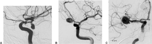 FIGURE 6-1. Aneurysm of the internal carotid artery at the origin of the posterior communicating artery (A), of the anterior communicating artery (B), and of the middle cerebral artery bifurcation (C). |
Large aneurysms frequently contain an intra-aneurysmal thrombus. Contrast-enhanced computed tomography (CT) and T1- and T2-weighted magnetic resonance imaging (MRI) may show the thrombus as a nonperfused compartment of an aneurysm. Partially thrombosed aneurysms always require several endovascular treatment sessions. Circumscribed narrowing of the parent artery proximal to the aneurysm, possibly in combination with a fusiform instead of a saccular vessel dilatation, indicates that an underlying dissection is the cause of aneurysm formation (Fig. 6-2). Dissecting aneurysms carry a particular risk of hemorrhage, re-hemorrhage, and continued growth after endovascular treatment.
Brain Arteriovenous Malformations
AVMs of the brain are congenital direct connections between pial arteries and the regional draining veins (arteriovenous shunt, AV shunt). The key finding on angiography is the opacification of veins during the early arterial phase (Fig. 6-3). The underlying cause is the absence of capillaries in a brain region of variable volume. An AV shunt is associated with locally decreased blood-flow resistance and increased blood-flow volume. The size of brain AVMs varies from a few millimeters to the size of a complete hemisphere. In the majority of AVMs, the diameters of both the feeding arteries and the draining veins are increased.
The connection between arteries and veins (nidus) may consist of a network of pathological vessels (plexiform nidus). Direct connections of varying caliber are also found (macro- or microfistula) (Fig. 6-4). In many AVMs the nidus shows both components. Further findings of interest are associated aneurysms, which may be found in the standard locations on the circle of Willis (proximal). Aneurysms close to or inside the AVM nidus (perinidal, intranidal) are sometimes less obvious. Peri- and intranidal aneurysms carry a high risk of bleeding and should be prime targets for the embolization.
In addition to the direct supply, leptomeningeal anastomoses may contribute to the AV shunt. This pattern is frequently associated with a proximal occlusion of cortical branches. The leptomeningeal collaterals to an AVM are less suitable for endovascular occlusion but can be obliterated during microsurgical excision of the AVM with relative ease. After partial embolization or incomplete surgical excision, but also independent of prior treatment, transdural feeding arteries may contribute to the AV shunt. These vessels can mostly be obliterated by endovascular means without further difficulty. Analysis of the venous drainage of an AVM sometimes shows stenoses or saccular dilatations (varix) of the draining veins, both of which may indicate an increased risk of bleeding. Since the course of the draining veins is important for the planning of the surgical excision, proper documentation of the phlebogram is mandatory.
Acute Thromboembolic Occlusion of Intracranial Vessels
A thrombus within an intracranial artery obliterates the vessel lumen partially or completely (Fig. 6-5). Angiography, which is almost always carried out as an emergency procedure, will show the site of artery occlusion. If the lumen is completely filled by the embolus, it will be impossible to recognize the length of the thrombus. Complete angiography of all intracranial vessels is required prior to further endovascular considerations. The diagnostic workup should show the available collaterals to the occluded artery and eventually associated lesions (e.g., atherosclerotic occlusions of supra-aortic vessels, intracranial aneurysms). Chronic occlusions, as opposed to acute embolic occlusions, which are not suitable for revascularization, can be recognized by the presence of extensive collaterals. In endovascular treatment, the thrombus can almost always be penetrated with a suitable microcatheter. Gentle injection of contrast medium distal to the thrombus will show the length of vessel occlusion (Fig. 6-5C). Atherosclerotic stenoses proximal to or at the level of the thrombotic vessel occlusion may warrant stent PTA after local fibrinolysis in order to avoid early reocclusion.
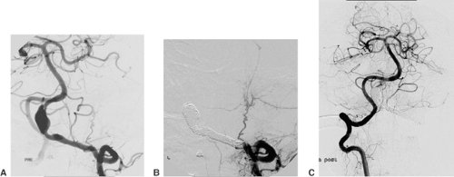 FIGURE 6-2. Fusing dissecting aneurysm of the vertebral artery (A), treated by coil occlusion of aneurysm and parent artery (B). The contralateral vertebral artery supplies the brain stem and cerebellum (C). |
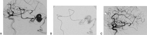 FIGURE 6-3. Brain arteriovenous malformation (AVM) with a plexiform nidus (A) and early opacification of the draining vein. The feeding artery was catheterized with a Marathon microcatheter (B). Subsequent injection of polymer glue (Histoacryl/Lipiodol mixture 1:5) resulted in a complete interruption of the arteriovenous shunt (C). |
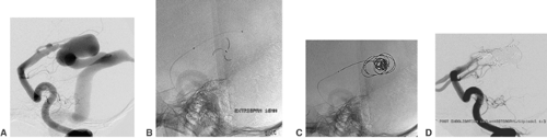 FIGURE 6-4. Macrofistula type of an AVM nidus in a child. Direct, large-caliber connection between the left posterior cerebral artery and the draining vein (A). Two TriSpan coils (16 mm) were detached in the varix (enlarged vein) adjacent to the fistula (B). The TriSpan devices prevented regular coils, which were subsequently inserted, from venous escape (C). The coils within the varix and at the level of the fistulous arteriovenous connection induced a sufficient reduction of the shunt. Complete occlusion of the fistula was achieved by the injection of 0.1 cc Histoacryl/Lipiodol 1:3. AVM, arteriovenous malformation (D). |
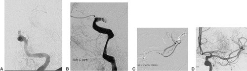 FIGURE 6-5. Internal carotid artery (ICA) and middle cerebral artery (MCA), obliterated by an embolus. Injection of the left internal carotid artery shows embolic occlusion of the vessel distally to the ophthalmic artery [(A,B); posterior and lateral view]. Penetration of the thrombus with a microcatheter was easily possible (C). Disintegration of the thrombus with a Catch device, partial thrombus removal with a 4F aspiration microcatheter (Penumbra device) and dilatation of a proximal M1 stenosis resulted in a complete restoration of the patency of the ICA and MCA (D). |
Atherosclerotic Intracranial Arterial Stenosis
Atherosclerotic stenoses relevant for endovascular treatment concern the intracranial internal carotid artery, the proximal middle cerebral artery, the intracranial vertebral artery, and the basilar artery (Fig. 6-6). Angiography should define the degree, the length, and the wall contour of the stenotic vessel segment. It is important to understand the collaterals to the stenosis and the vasculature proximal and distal to it. Extreme vessel tortuosity or a long (>10 mm) and irregular stenosis are arguments against endovascular treatment. Angiographic images that show the stenosis without foreshortening and that are free from superimposed vessels must be obtained. Because of the variability of vessel anatomy, no standard projections can be proposed for this purpose. Exact measurement of the vessel diameter proximal and distal to the stenosis is helpful for
balloon and stent sizing. Most DSA units provide integrated measurement software for calibrated vessel diameter determination and quantification of stenoses.
balloon and stent sizing. Most DSA units provide integrated measurement software for calibrated vessel diameter determination and quantification of stenoses.
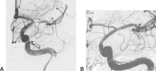 FIGURE 6-6. Stenosis of the left middle cerebral artery, incidentally observed with rapid progression during the angiographic follow-up of a ruptured and subsequently coiled MCA bifurcation aneurysm (A). The stenosis was successfully treated by undersized balloon dilatation, followed by the deployment of a self-expanding Neuroform stent (B). MCA, middle cerebral artery. |
Occipital Dural Arteriovenous Fistula
In so-called occipital dural AV fistulas, angiography of the ipsilateral external carotid artery shows early opacification of the sigmoid/transverse sinus (Fig. 6-7). The potentially supplying branches are the occipital artery (mastoid perforators), the stylomastoid artery, the retroauricular artery, the ascending pharyngeal artery (neuromeningeal branch), the middle and/or posterior meningeal artery, and the marginal tentorial branches of the meningohypophyseal trunk. Further supply from dural branches of the vertebral artery and from pial arteries (e.g., the posterior communicating artery) is frequently found. The occipital sinus can be completely patent and allow drainage of the fistula. Alternatively, sequelae of previous thromboses can be present and may obstruct the sinus to varying degrees. This can cause drainage of the fistula through the sinus in a retrograde direction (i.e., toward the torcular instead of the jugular bulb). The outlet of the arteries supplying the fistula is in the wall of the venous sinus, adjacent to the draining veins. This neighborhood allows the establishment of a direct AV shunt from the supplying arteries into cortical draining veins. The likelihood of this cortical drainage pattern increases with more prominent thrombotic changes of the sinus. Accelerated perfusion of superficial veins in a retrograde direction (i.e., away from the dural venous sinus) is the key finding of cortical venous drainage and associated with a significant risk of intracranial hemorrhage.
Arteriovenous Fistula Between the Carotid Artery and the Cavernous Sinus
The common feature of fistulas between the carotid artery and the cavernous sinus (carotid cavernous sinus fistula, CCF) is the AV shunt into the cavernous sinus and the afferent veins. Direct fistulas either are related to a head trauma with an injury of the wall of the internal carotid artery or result from the rupture of an aneurysm of the cavernous segment of the internal carotid artery into the cavernous sinus (Fig. 6-8). Dural fistulas are completely different in nature. Their supply may come from dural branches of the internal carotid artery and the external carotid artery of one or both sides. The fistula is generally located on the posterior aspect of the cavernous sinus of one side or on the intercavernous sinus. The shunt volume of dCCFs may vary over a wide range but is mostly only a fraction of the shunt volume of direct CCFs. The drainage runs through the superior and inferior ophthalmic veins, which are perfused in a retrograde direction (i.e., from the cavernous sinus toward the angular vein). Further possible routes of drainage are all veins connected to the cavernous sinus (e.g., superior and inferior petrosal sinus, sphenoparietal sinus) (Fig. 6-9). The CCF drainage via cortical veins implies a risk of intracranial hemorrhage. Postthrombotic changes of the orbital veins are associated with a reduced shunt volume and more severe ocular symptoms.
Standard Procedure
Any endovascular procedure starts with a predefined treatment plan, based on the analysis of available CT, MRI/MRA, and DSA examinations. Other decisions concern preprocedural
medication (e.g., antiaggregation prior to stent deployment), preparation for treatment under general anesthesia or with local anesthesia, and the size and number of guiding catheters. From the beginning of the treatment, it is usually obvious whether one or several sessions will be required. If more than one session is needed, the most dangerous (part of the) lesion should be addressed first. It may, however, be necessary to deal first with less threatening lesions in order to get a well-controlled access to the main pathology. A typical example for this situation is the stent PTA of a proximal stenosis of the internal carotid artery in order to provide optimized conditions for the catheterization and coil occlusion of an intracranial aneurysm.
medication (e.g., antiaggregation prior to stent deployment), preparation for treatment under general anesthesia or with local anesthesia, and the size and number of guiding catheters. From the beginning of the treatment, it is usually obvious whether one or several sessions will be required. If more than one session is needed, the most dangerous (part of the) lesion should be addressed first. It may, however, be necessary to deal first with less threatening lesions in order to get a well-controlled access to the main pathology. A typical example for this situation is the stent PTA of a proximal stenosis of the internal carotid artery in order to provide optimized conditions for the catheterization and coil occlusion of an intracranial aneurysm.
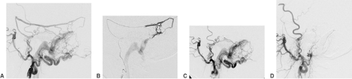 FIGURE 6-7. So-called occipital dural arteriovenous fistula. Injection of the left ECA shows the enlarged middle meningeal and occipital arteries, with multiple branches converging to the sigmoid sinus (A). Within the lumen of the sigmoid sinus, remnants of a previous thrombotic occlusion are still visible as streaky defects in the opacification. The direction of venous drainage is orthograde toward the jugular bulb, without drainage via cortical veins. The arterial supply was reduced by selective catheterization of the middle meningeal and occipital arteries with injection of Histoacryl/Lipiodol (B,C). Complete interruption was achieved by dense filling of the affected sigmoid sinus with electrolytically detachable fibered coils (D). ECA, external carotid artery. |
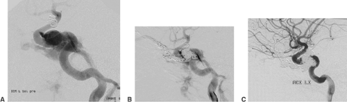 FIGURE 6-8. Direct carotid-cavernous sinus fistula following a car accident with head injury in a 14-year-old boy, presenting with chemosis and proptosis of the left eye. The injection of the left ICA shows an early opacification of the surrounding cavernous sinus and the inferior petrosal sinus (A). (The coils projecting on the distal ICA are within a dissecting aneurysm of the right ICA.) Via a transvenous access through the inferior petrosal sinus the left superior and inferior ophthalmic veins and the left cavernous sinus were occluded with electrolytically detachable fibered coils (B). Despite dense filling of the veins, complete interruption of the arteriovenous shunt was not achieved during the procedure. Angiographic follow-up 2 weeks later confirmed the patency of the left ICA and occlusion of the pre-existing arteriovenous fistula (C). The ocular symptoms had completely resolved. ICA, internal carotid artery. |
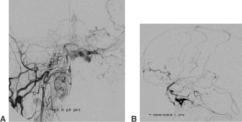 FIGURE 6-9. Dural carotid-cavernous sinus fistula without ocular but with extensive cortical drainage. Injection of the right ECA (frontal view) shows several dural branches, converging toward the left cavernous sinus, with venous drainage via cortical veins (A). Microcatheter injection of the left cavernous sinus confirms both the complete thrombotic occlusion of the left ophthalmic veins and the drainage via the sphenoparietal sinus and the basal vein of Rosenthal (B). ECA, external carotid artery. |
The vast majority of procedures can be carried out using standardized access products. They comprise a 6F or 8F sheath (11 cm long; e.g., Cordis), a 6F or 8F guiding catheter (e.g., Guider Softip, Boston Scientific), and a 0.035-in. guidewire (e.g., Radiofocus, Terumo). As steerable microcatheters, we prefer Nautica, Echelon14, and Echelon10 together with SilverSpeed16, -14, or -10 microguidewires (MTI/ev3). Another good option with a remarkable atraumatic tip is Synchro14 or -10 (Boston Scientific).
The two most frequently used self-expanding stents for intracranial vessels are Neuroform (Boston Scientific) and Leo (Balt). The Neuroform stent has an open cell design, comes premounted in a two-microcatheter set, and is very flexible and atraumatic. A drawback is the need for an inner 0.010-in. or 0.014-in. microguidewire (X-celerator10, MTI/ev3, works best). Distal vessel injury from this wire remains a serious concern. The stent itself is not very stable and can easily be destroyed after deployment by forced catheterization.
The braided Leo stent is introduced through a microcatheter (Vasco, Balt) without an inner guidewire, is quite robust, and has radiopaque markers along two struts. Aneurysm coverage is better with the Leo. The Vasco microcatheter for this stent is less flexible than the Neuroform catheter (Renegade Hi Flo, Boston Scientific), and the Leo stent appears more traumatic and thrombogenic. There are several coil systems available that differ in the mode of detachment and the shape, stiffness, and surface of the implant. Electrolytic detachment is convenient and reliable. The efficacy of so-called bioactive coil surfaces (e.g., Matrix, Boston Scientific) and hydrogel-coated coils (Hydrocoils, Microvention) is questionable. Coils with an imprinted three-dimensional shape are most useful for the treatment of wide-necked aneurysms (e.g., from Micrus or MTI/ev3). Soft coils are provided by several companies (e.g., Boston Scientific, Micrus, MTI/ev3). We have achieved very good results with detachable nylon fibered coils (MTI/ev3).
Intracranial Aneurysms
The incidence of intracranial aneurysms in the general population has been estimated to be 3% to 6%.15 The frequency of aneurysmal subarachnoid hemorrhage (SAH) is in the range of 6 to 10 per 100,000 persons per year. The mortality from SAH is about 50%.16,17 Although the frequency and clinical relevance of intracranial hemorrhage secondary to previously unruptured aneurysms have been a matter of debate in recent years, no conclusive recommendations are available at present. Initially, a very low rupture rate was reported for aneurysms
≤10 mm in diameter,18 but these figures were later updated, and the actual rate of rupture may be higher. The reported rate depends on the site and size of the aneurysm and the patient’s specific risk factors.19
≤10 mm in diameter,18 but these figures were later updated, and the actual rate of rupture may be higher. The reported rate depends on the site and size of the aneurysm and the patient’s specific risk factors.19
The presence of an intracranial aneurysm may be confirmed by a contrast-enhanced CT or an MRI examination.20 CT angiography has been significantly improved and is now frequently employed diagnostically. Final decision making, however, is still mostly based on a selective catheter angiography. Angiography should comprise a series of oblique and magnified views of the aneurysm. Rotational angiography with three-dimensional rendering is sometimes quite useful. A pretreatment angiogram should clearly reveal the size, shape, location, and adjacent vessels of the target aneurysm.
In patients with a ruptured aneurysm, the need for treatment is evident. Empirical data has revealed that the clinical results after endovascular treatment of ruptured aneurysms are better than after surgical clipping.21 In unruptured aneurysms, the decision regarding treatment has to take several factors into account. Statistical data is of limited help in individual patients. During surgery of unruptured aneurysms, it became evident that among aneurysms with essentially the same angiographic appearance some could have a thick, fibrous wall, insinuating a low tendency to rupture, whereas others have very thin and fragile walls. Because current diagnostic techniques do not allow any reliable distinction between thick- and thin-walled aneurysms, this feature can only be evaluated after surgical preparation. At present, the decision to treat is favored by a majority of patients.
Other important factors to be considered are the patient’s age, coexisting illnesses, and the anticipated technical ability to exclude a given aneurysm by either surgical or endovascular means. Ultimately, however, the patient decides which treatment option he or she prefers. In general, we offer patients with an unruptured aneurysm—regardless of its size—either endovascular or surgical treatment whenever it appears technically feasible. The location of the aneurysm is irrelevant for the chances and risks of endovascular treatment. Technical difficulty may be anticipated in the case of very tortuous proximal vessels, in very small (i.e., ≤2 mm diameter) and in giant (>25 mm diameter) aneurysms, in those with a very wide neck (>4 mm), and in the case of a fundus-to-neck ratio <1. Proximal vessels without severe atherosclerosis and aneurysms with a well-circumscribed neck are ideally suitable for endovascular coil occlusion.
Technical Aspects of Coil Occlusion of Intracranial Aneurysms
It is necessary that the guiding catheter has stable, atraumatic, and controlled access to the respective supra-aortic artery. After insertion of the sheath into the right and/or left femoral artery, a standard 5F or 6F diameter guiding catheter (e.g., Guider Softip, Boston Scientific) that is 90 or 100 cm long is positioned using a 0.035-in. guidewire such as Radiofocus (Terumo). A continuous flush with a heparinized saline solution via a rotating hemostatic valve (RHV) is required to prevent formation of thrombi.
Self-mounted coaxial systems are an alternative; examples are a 100-cm-long 6F guiding catheter inside another (90-cm-long 8F), or a 100-cm-long 8F guiding catheter inside a 90-cm-long 10F guiding catheter. Direct puncture of the common carotid artery, using a LeaderCath G14 (Vygon), provides even better support and stability and can be used in the case of difficult peripheral access. Since direct puncture of the common carotid artery may result in vessel dissection and stroke, accurate puncture and gentle insertion of the guidewire and the Teflon sheath under fluoroscopy without increased force are mandatory. Options for alternate access to the posterior circulation are insertion of a 6F sheath into the axillary artery and the use of a 6F internal mammaria artery guiding catheter.
Before beginning treatment, the angiographic images of the target aneurysm must be thoroughly analyzed. Most important is that the appropriate working projections are acquired, showing if possible the aneurysm in its full length, without overlying vessels, and in clear relation to the parent artery and to vessels originating in its proximity. Although rotational angiography with three-dimensional rendering is sometimes helpful for determining the presence, location, and geometry of the aneurysm,22 its importance appears to be overestimated. Factors that are likely to be more important for successful endovascular aneurysm treatment are high image magnification, low image noise, optimal spatial resolution, and a road-map function with a well-adapted contrast setting.
As soon as a suitable angiographic working projection has been determined, a dual marker microcatheter (i.e., with two radiodense markers, one at the distal tip of the microcatheter and one marker 3 cm proximal to it) will be selected based on the location and geometry of the target aneurysm. The outer diameter (OD) of the microcatheter appears in most cases to be of lesser importance. The microcatheter should, however, be stable in its later position with the tip adjacent to or inside the aneurysm. During insertion of the coils, it may become necessary to pull or to push the microcatheter, which should follow these intended movements as precisely as possible. Inner diameters (IDs) that are too small may restrict the choice of usable devices. These requirements are sufficiently met by microcatheters such as Nautica (OD 2.2F, 0.71 mm; ID 0.018-in., 0.46 mm, MTI/ev3) or Excelsior1018 (OD 2.0F, 0.66 mm; ID 0.019-in., 0.48 mm, Boston Scientific). Preshaped microcatheters such as the Echelon14 (MTI/ev3) with a given tip angulation of 45 degrees or 90 degrees remain quite stable in this position. Vessels with a naturally small caliber or whose lumen is reduced due to vasospasm may require a thinner microcatheter. Echelon10 (OD 1.7F, 0.57 mm; ID 0.017-in., 0.43 mm, MTI/ev3) and Excelsior SL-10 (OD 1.7F, 0.56 mm; ID 0.0165-in., 0.43 mm, Boston Scientific) are among the suitable ones. If a straight microcatheter is used, proper shaping is important. The shape to be imprinted on the catheter tip by steam or dry heat has to anticipate the route the microcatheter has to follow until reaching the aneurysm, as well as the angle at which the microcatheter will enter the aneurysm neck. Wrong shaping can result in failure to coil an aneurysm. Proper shaping relies on skill and experience.
The microguidewire that is used with the microcatheter should be sufficiently radiopaque, should precisely follow applied torque movements, and must not cause significant friction in the microcatheter or the intracranial vessel. An atraumatic tip is most important. The SilverSpeed10 and SilverSpeed14 wires (MTI/ev3) are our standard micro-guidewires. The Synchro10 and Synchro14 microguidewires (Boston Scientific) follow torque movement in an excellent
way, and the tip is very soft. The Synchro wire is recommended for more challenging vessels. All these wires come straight and require individual shaping. A more or less steep curve, similar to the shape that was given to the microcatheter, is usually appropriate.
way, and the tip is very soft. The Synchro wire is recommended for more challenging vessels. All these wires come straight and require individual shaping. A more or less steep curve, similar to the shape that was given to the microcatheter, is usually appropriate.
Catheterization of the aneurysm is then carried out using the just-mentioned working projection under road-map fluoroscopy. Slow advancement of the microcatheter and micro-guidewire is crucial. Most frequently, the microguidewire is slightly pushed forward, and the microcatheter is then pushed while pulling on the guidewire gently. Perfect control of both movements is the key. The reason for any resistance has to be found and removed. Potential sources of increased resistance include inadvertent proximal looping of the microcatheter, displacement of the tip of the guiding catheter from the internal into the external carotid artery, or vasospasm anywhere in the course of the microcatheter. Under no circumstances should the operator be tempted to overcome the resistance by pushing harder.
The aneurysm is then partly entered by the tip of the microguidewire. Any contact between the aneurysm wall and the tip of the wire should be avoided. Daughter aneurysms (i.e., small additional sacs, bulging out of the contour of the aneurysms) are very fragile and may not be touched with either the wire or the tip of the following microcatheter. In most aneurysms the ideal position for the tip of the microcatheter is at the level of the aneurysm neck. The aneurysm is filled with coils from its neck inward (Fig. 6-10). This again underlines the importance of a stable microcatheter and explains why the diameter of the aneurysms is generally irrelevant in selecting the size of the microcatheter.
The selection of the coils to be inserted has to address several aspects. The most frequently used implants are electrolytically detachable platinum coils (GDC, Boston Scientific; NXT MTI/ev3), in which direct current is used to separate the platinum coil from an insertion wire. The original concept of electrothrombosis, induced by the application of direct current (which is also used for coil detachment), turned out to be nonfunctional.23 Mechanically detachable coils (Detach, Cook) are not well suited for aneurysms. These coils are attached to an insertion wire via a winding. Detachment is achieved by turning the insertion wire against the coil with a potential transmission of this movement to the coil. Two coil systems are based on hydrodynamic detachment (Microvention, Cordis). The coil is attached to a thin tube using a distal valve mechanism. The valve is opened, and the coil is detached by injecting saline solution or diluted contrast medium. The Micrus coil system uses an electrothermal mechanism (i.e., electric heating of a wire with disruption of a polymer fiber) for coil detachment.24
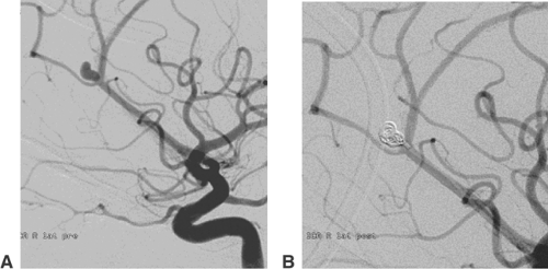 FIGURE 6-10. Proper position of the tip of a microcatheter for filling an aneurysm with coils from outside. Small aneurysm of the right pericallosal artery (A). The position of the tip of the microcatheter adjacent to the neck but outside the aneurysmal sac was maintained throughout the entire procedure (B). This requires a robust microcatheter, resilient to “kick back” effects, in a stable position. |
The process of filling an aneurysm with coils may start with a regular coil or, in the case of a wide aneurysm neck (≥4 mm), with a coil with an imprinted three-dimensional shape.25,26 The diameter of the aneurysmal sac and of the first coil should be equal. Subsequent coils are inserted and detached until the aneurysm sac accepts no further coil material. Dense filling is mandatory for the result of treatment to be stable. In the case of wide-neck aneurysms, the parent artery can temporarily be protected by the inflation of a nondetachable compliant balloon (Fig. 6-11).27 Hyperglide and Hyperform (MTI/ev3) work very well for this purpose.28 During this “balloon remodeling,” parent vessel occlusion should be limited to intervals of <3 minutes, especially if the collaterals to the artery affected are absent or of dubious sufficiency. Balloon remodeling is mostly performed via an 8F guiding catheter. It is sometimes easier if the balloon catheter is first brought in front of the aneurysm and the microcatheter is introduced afterward. Several publications mention that the frequency of complications (thromboembolic or vessel dissection) is increased in balloon remodeling procedures.29
The coil treatment of wide-necked aneurysms can also be supported by deploying a self-expanding stent. Neuroform (Boston Scientific) is a very flexible nitinol stent with an open-cell design30 (Fig. 6-12). The Leo stent (Balt) is a more stable but also a more thrombogenic closed-cell device.31 The Solo stent is electrolytically detachable and fully retrievable (Fig. 6-13). Before stent deployment, profound medical antiaggregation has to be started. The usual protocol includes loading doses of 500 mg acetylsalicylic acid (ASA) and 300 mg clopidogrel 3 days before the treatment. Medical antiaggregation makes stent-assisted procedures less suitable for treatment in the acute phase after aneurysm rupture. With either device, it is possible to deploy the stent and catheterize the aneurysm afterward with a microcatheter.32 In this case, it is recommended that coil insertion be delayed for 6 to 8 weeks after stent deployment for unruptured aneurysms. In the meantime the deployed stent will become integrated into the wall of the parent vessel. Alternatively, it is possible to catheterize the aneurysm with a microcatheter, deploy the stent over the aneurysm orifice, and coil the aneurysm afterward (“jailed catheter”). The microcatheter can always be pulled out of the parent artery.
TriSpan (Boston Scientific) is a modified coil with three partly radiopaque nitinol petals33 (Fig. 6-14). These petals in the shape of a flower blossom are placed and opened in the neck level of the aneurysm. Wide-necked bifurcation aneurysms are frequently well suitable for this treatment strategy. The TriSpan coil is introduced and kept in place via a large-lumen and robust microcatheter (e.g., RapidTransit, Cordis; Excelsior1018, Boston Scientific; Nautica, MTI/ev3). For coil insertion, a second microcatheter is used. Simultaneous insertion of two microcatheters requires an 8F guiding catheter with a double RHV. The TriSpan remains attached to the insertion wire until coil insertion is completed. In order to avoid premature TriSpan detachment, it is required that the detachment zone of the TriSpan remain covered by the
microcatheter until voluntary detachment. We usually open the TriSpan proximal to the final level of occlusion. Via a second microcatheter a slightly undersized three-dimensional coil (e.g., Boston Scientific, Micrus, MTI/ev3) is inserted. As soon as this three-dimensional coil is fully pushed out of the microcatheter, the TriSpan device together with the concerning microcatheter is gently advanced until the three-dimensional coil starts to be compressed. The three-dimensional coil is detached as soon as the TriSpan device achieves stabilization. During the following process of coil insertion, the TriSpan coil can be manipulated in a way that avoids coil displacement out of the aneurysm into the parent vessel. Fibered coils (MTI/ev3) are especially useful for the treatment of these aneurysms. The fibers facilitate fixation of the TriSpan pedals at the coil mesh and prevent major recurrence due to coil compaction.
microcatheter until voluntary detachment. We usually open the TriSpan proximal to the final level of occlusion. Via a second microcatheter a slightly undersized three-dimensional coil (e.g., Boston Scientific, Micrus, MTI/ev3) is inserted. As soon as this three-dimensional coil is fully pushed out of the microcatheter, the TriSpan device together with the concerning microcatheter is gently advanced until the three-dimensional coil starts to be compressed. The three-dimensional coil is detached as soon as the TriSpan device achieves stabilization. During the following process of coil insertion, the TriSpan coil can be manipulated in a way that avoids coil displacement out of the aneurysm into the parent vessel. Fibered coils (MTI/ev3) are especially useful for the treatment of these aneurysms. The fibers facilitate fixation of the TriSpan pedals at the coil mesh and prevent major recurrence due to coil compaction.
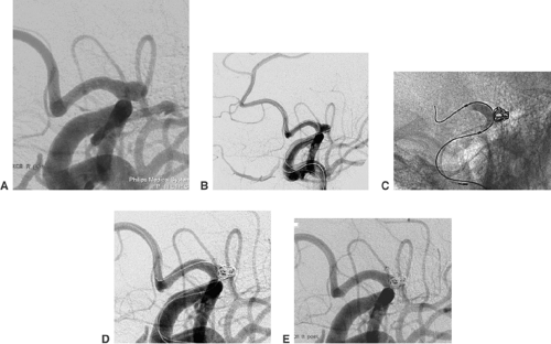 FIGURE 6-11. Balloon remodeling for the treatment of a wide necked aneurysm. Aneurysm of the proximal A1 segment without a circumscribed neck (A). Catheterization of the right ACA with a Hyperglide balloon microcatheter while the tip of a second microcatheter is already within the aneurysm sac (B). Temporary filling of the balloon during insertion of coils into the aneurysm (C). The aneurysm is already filled, while balloon-catheter and microcatheter are left in place for several minutes (D). Patency of the parent artery and complete occlusion of the aneurysm after gentle withdrawal of both catheters (E). ACA, anterior cerebral artery. |
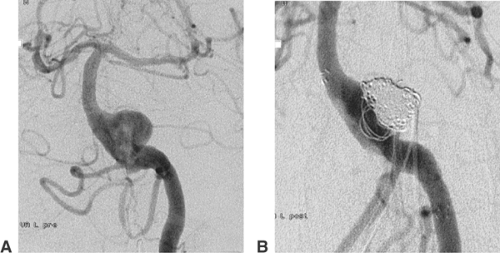 FIGURE 6-12. Treatment of a wide-necked aneurysm of the proximal basilar artery with stent-assisted coil occlusion. Injection of the left vertebral artery shows a wide-necked aneurysm immediately distal to the vertebral artery junction (A). After deployment of a self-expanding Neuroform stent, the aneurysm was filled with platinum coils (B). |
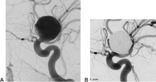 FIGURE 6-13. Treatment of a wide-necked aneurysm with a Solo stent. Large and wide-necked aneurysm of the right internal carotid artery in paraophthalmic location (A). Deployment of a self-expanding stent, followed by complete coil occlusion of the aneurysm (B). |
An underexploited strategy for the treatment of dissecting and fusiform aneurysms is the parent vessel occlusion (PVO) with coils. PVO is feasible whenever a sufficient collateral circulation is available. Even fusiform aneurysm of the trunk of the basilar artery can be treated by PVO if at least one posterior communicating artery and the P1 segment concerned have a significant diameter34 (Fig. 6-15). Mycotic aneurysms mostly result from infected cardiogenic emboli in brain arteries. A transient embolic occlusion of the parent artery is part of the specific pathogenesis. For these lesions, the appropriate treatment is usually the occlusion of the aneurysm and parent vessel with coils or/and polymer glue.35
Alternatives to Coil Occlusion
The use of the liquid embolic agent Onyx HD 500 (MTI/ev3) together with temporary balloon protection of the parent vessel, which was advocated by several authors, has now been
widely abandoned because of unacceptable high complication rates.36 The available stent grafts (e.g., GraftMaster, Abbott) are not optimized for intracranial purposes. They are too stiff and require excessive inflation pressures (16 atm), and should therefore only be used for intracranial aneurysms if other options have failed.37 If there is no alternative to using such a stent graft, medical antiaggregation is required (loading dose 500 mg ASA, 300 mg clopidogrel). Sufficient backup has to be provided by the guiding catheter. A coaxial system with a 100-cm-long, 6F catheter inside a 90-cm-long, 8F guide catheter may work. It has proved helpful to make the extracranial internal carotid artery straighter and stiff by preparatory deployment of a self-expanding stent (e.g., a 7 mm/40 mm Protegé, ev3). Direct puncture of the common carotid artery using a 14 G Leader Catheter (Vygon) set provides optimal support but is considered more invasive than a transfemoral approach. Adding nimodipine to the guiding catheter flush (15 mL nimodipine [Nimotop] per 1000 mL saline solution) and the prophylactic injection of glycerin trinitrate (2 mg per injection diluted in 8 mL saline solution) are helpful. A 0.014-in. guidewire has to be inserted far distally into a cortical branch of the middle communicating artery or posterior communicating artery, which always bears the risk of a vessel injury. The passage of these stent grafts is usually easier through the atlas loop than through the cavernous segment of the internal carotid artery. Short stent grafts (e.g., 9 mm or 12 mm) follow much more easily than longer ones.
widely abandoned because of unacceptable high complication rates.36 The available stent grafts (e.g., GraftMaster, Abbott) are not optimized for intracranial purposes. They are too stiff and require excessive inflation pressures (16 atm), and should therefore only be used for intracranial aneurysms if other options have failed.37 If there is no alternative to using such a stent graft, medical antiaggregation is required (loading dose 500 mg ASA, 300 mg clopidogrel). Sufficient backup has to be provided by the guiding catheter. A coaxial system with a 100-cm-long, 6F catheter inside a 90-cm-long, 8F guide catheter may work. It has proved helpful to make the extracranial internal carotid artery straighter and stiff by preparatory deployment of a self-expanding stent (e.g., a 7 mm/40 mm Protegé, ev3). Direct puncture of the common carotid artery using a 14 G Leader Catheter (Vygon) set provides optimal support but is considered more invasive than a transfemoral approach. Adding nimodipine to the guiding catheter flush (15 mL nimodipine [Nimotop] per 1000 mL saline solution) and the prophylactic injection of glycerin trinitrate (2 mg per injection diluted in 8 mL saline solution) are helpful. A 0.014-in. guidewire has to be inserted far distally into a cortical branch of the middle communicating artery or posterior communicating artery, which always bears the risk of a vessel injury. The passage of these stent grafts is usually easier through the atlas loop than through the cavernous segment of the internal carotid artery. Short stent grafts (e.g., 9 mm or 12 mm) follow much more easily than longer ones.
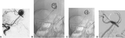 FIGURE 6-14. TriSpan procedure for the endovascular treatment of a wide-necked bifurcation aneurysm. Injection of the right ICA shows an unpaired ACA (A2) with an aneurysm, located at the ICA bifurcation (A). The aneurysm is catheterized with two microcatheters. 3D coils are inserted into the aneurysm, held in place and occasionally compressed by a TriSpan coil (B,C). The final injection of the ICA confirms complete filling of the aneurysm with reconstruction of the parent artery bifurcation (D). ICA, internal carotid artery; ACA, anterior cerebral artery. |
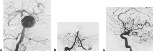 FIGURE 6-15. Fusiform aneurysm of the basilar trunk after partial coil treatment in another institution several years before (A). The aneurysm was excluded from circulation by endovascular coil occlusion of parent artery and aneurysm after tolerated balloon test occlusion (B). The upper part of the basilar artery and both superior cerebellar arteries are supplied via the posterior communicating artery (C). |
The injection of rapidly solidifying polymer glue has great potential for treating intracranial aneurysms. In contrast to the precipitating Onyx HD 500, which remains separated from the aneurysm wall, the polymer glue becomes firmly attached to it. Although occlusion of intracranial aneurysms has been achieved using this technique, unresolved issues are the precise control of the injected glue volume and reproducible avoidance of escape of glue to the distal vessels.38
Stay updated, free articles. Join our Telegram channel

Full access? Get Clinical Tree


