Intracoronary Ultrasound
Anuja Nair
M. Pauliina Margolis
Stephen C. Davies
D. Geoffrey Vince
The ideal in vivo imaging technique for atherosclerosis and guiding interventions should be safe, relatively inexpensive, and portable, and it should provide high-resolution images in real time. In addition, the image data should provide information that is comparable to the microanatomical and histological gold standard to allow appropriate clinical decisions in the course of vascular catheter-based interventions. Whereas contrast angiography has been the traditional mode of viewing coronary arteries in interventional settings, clinical intravascular ultrasound (IVUS) represents a relatively recent development in the field that has already gained significant acceptance over the past decade (for review, see reference 1).
This chapter aims to explain the principles of IVUS technology and image acquisition and the valuable information that can be obtained from ultrasound signal backscatter. Analysis of ultrasound signal backscatter can be used to create color-coded tissue maps of a plaque or VH-IVUS images, which provide crucial knowledge of the vascular disease at a target lesion or target artery.
Principles of Ultrasound
The term ultrasound indicates sound of frequency higher than the extent of human hearing range, which is 20 Hz to 20 kHz. Barring bats, dolphins, whales, and certain rodents, most animals can hear up to only approximately 45 to 50 kHz. Any sound of frequency higher than the human range of hearing (usually >20 kHz) is considered to be ultrasound. Sound energy moves through media like a wave and is therefore subject to laws of wave motion. Since the propagation is also dependent on the medium the sound energy transverses, any changes to the original wave are indicative of the properties of that medium. Therefore, by studying these changes to the ultrasound waves, one can reasonably derive conclusions about composition of any such media. However, it is important to understand the underlying principles of ultrasound waves to extract information from them.
The first instance of cardiac imaging with ultrasound was perhaps the development of echocardiography by Elder in the early 1950s (for review, see reference 2). Like other ultrasound research in that period, medical diagnosis suffered from poor ultrasound transducer design and primitive algorithms for image display. As a result, the images could be interpreted to detect major tissue outlines but lacked information about detailed tissue texture. With the pulse-echo mode of operation, a single ultrasound beam is transmitted in tissue, and the resulting echoes that “bounce” off the different tissue interfaces are acquired by the ultrasound console. The distance between these echoes is indicative of the dimensions of the tissue structures. Their amplitudes and frequency content can be further analyzed to determine the type of tissue or its composition. The usage of medical ultrasound and its development increased tremendously following improvements in image processing techniques.3,4 Currently, a major characteristic of the typical gray-scale IVUS images is that they are a result of envelope-detection and log compression of the backscattered data. Briefly, envelope detection is a technique where the amplitude of a signal is noted along distance or time. All the highs and lows are then log compressed and the amplitudes are mapped to a value between 0 and 255, resulting in 8-bit resolution or 256 gray-scale levels in one image (see Fig. 3C-1 for schematic). Thus, IVUS images are only representative of the amplitude or strength of signals and they do not represent the frequency content of the signals. Subsequent subsections of this chapter explain why both signal strength and frequency are important in interpreting ultrasound data.
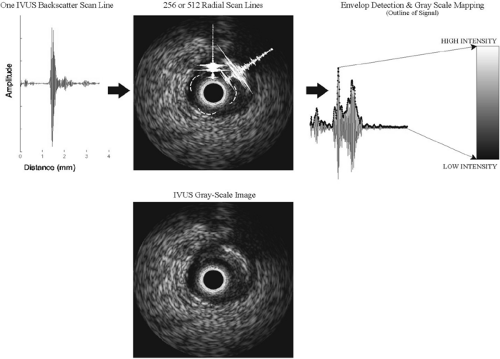 FIGURE 3C-1. Conventional intravascular ultrasound (IVUS) images are reconstructed from 256 or 512 single backscatter scan lines that span 360 degrees for one cross-sectional image. The “peaks” and “valleys” of these backscatter signals are identified by a technique called envelope detection. The lowest value of this signal is assigned black, and the highest value is assigned white. All signals in between are various shades of gray, resulting in a gray-scale cross-section IVUS image. |
Ultrasound Propagation in Tissue
In the pulse-echo mode of operation, the ultrasound transducer is excited with a certain voltage, which makes it oscillate and produce an ultrasound pulse. This is characteristic of piezoelectric materials, which are commonly chosen as ultrasound transducers. The reflected or scattered echoes of the original ultrasound are converted to an electrical signal and called the backscatter. With IVUS, an ultrasound pulse or wave is sent out into the vessel wall to be imaged in the radial direction. In the clinically available consoles, the backscatter is acquired by the transducer, with typically 256 or 512 such A-scans (backscattered signals) forming one IVUS arterial cross-sectional image (Fig. 3C-1). Analysis of these A-scans holds potential for tissue characterization.
Ultrasound propagation is generally approximated as a compression or longitudinal wave. For simplicity, this propagation can be approximated in one dimension using equations of wave motion where the speed of sound, c, in the medium is:
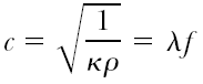 with κ being the compressibility of the surrounding medium and ρ its density; λ is the wavelength and f is the frequency of ultrasound.2,3 This simple representation of sound-wave propagation demonstrates how backscattered signals acquired with ultrasound medical systems are attributed to the tissue properties they are reflected from, namely density and compressibility, both contained in the amplitude and frequency spectrum of the ultrasound backscatter. The backscattered signals are composed of two types of signal echoes that are visible in IVUS gray-scale images. These are specular reflections and diffuse scattering.4,5 The specular echoes are a result of strong ultrasound reflections and refractions from an interface and are governed by a relationship between the angles of incidence, reflection, and refraction and the acoustic impedances of the two tissues at the interface. Such reflections are obvious in major tissue transitions, such as the blood-plaque or the media-adventitia wall interface (see Fig. 3C-2). In addition, in ultrasound systems where the same transducer is also the receiver for the backscatter (e.g., the current IVUS catheters), detection of specular echoes are highly dependent on the angle of incidence. If the angle is large, the reflected wave will not be detected; only
reflections off perpendicular interfaces and those with small angles are received by the IVUS catheter and hence displayed in an image. Studies have been conducted to examine the effect of angle of incidence of ultrasound with respect to the plaque, and results have indicated some dependency to tissue characterization.6,7 The second type of ultrasound scattering, called diffuse scattering, is from tissue microstructure at cellular or subcellular levels. Diffuse scatter is due to a phenomenon of scattering from structures smaller in dimension than the ultrasound wavelength, often called Rayleigh scattering.8 These reflections are independent of the angle of incidence and they result in the speckled appearance of tissue in IVUS gray-scale images.4,9 Since the ultrasound scattering is in many directions, only a small portion of the signal is reflected back to the ultrasound transducer. Given the low intensities observed with diffuse scattering, in comparison to specular reflections, diffuse scatter is often attributed to noise in the signals. Detailed studies have demonstrated that ultrasound attenuation due to diffuse scattering is small. However, this phenomenon is considered important for discerning soft tissue detail.10,11 It is observed as “speckle” in the log compressed gray-scale ultrasound images. IVUS images of atherosclerotic plaques constitute mostly diffuse scattering, except for the specular reflections off the vessel-wall boundaries or in plaques with large areas of dense calcium (as shown in Fig. 3C-2).
reflections off perpendicular interfaces and those with small angles are received by the IVUS catheter and hence displayed in an image. Studies have been conducted to examine the effect of angle of incidence of ultrasound with respect to the plaque, and results have indicated some dependency to tissue characterization.6,7 The second type of ultrasound scattering, called diffuse scattering, is from tissue microstructure at cellular or subcellular levels. Diffuse scatter is due to a phenomenon of scattering from structures smaller in dimension than the ultrasound wavelength, often called Rayleigh scattering.8 These reflections are independent of the angle of incidence and they result in the speckled appearance of tissue in IVUS gray-scale images.4,9 Since the ultrasound scattering is in many directions, only a small portion of the signal is reflected back to the ultrasound transducer. Given the low intensities observed with diffuse scattering, in comparison to specular reflections, diffuse scatter is often attributed to noise in the signals. Detailed studies have demonstrated that ultrasound attenuation due to diffuse scattering is small. However, this phenomenon is considered important for discerning soft tissue detail.10,11 It is observed as “speckle” in the log compressed gray-scale ultrasound images. IVUS images of atherosclerotic plaques constitute mostly diffuse scattering, except for the specular reflections off the vessel-wall boundaries or in plaques with large areas of dense calcium (as shown in Fig. 3C-2).
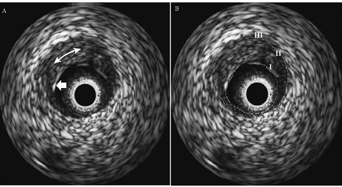 FIGURE 3C-2. A: Intravascular ultrasound (IVUS) image with specular reflection (block arrow) and diffuse scattering (double-headed arrow). B: Same image with segmented plaque illustrating the three-layer appearance of IVUS images. I, echogenic lumen-plaque boundary; II, echolucent media; III, echogenic adventitia. |
Ultrasound-Tissue Interactions
Ultrasound energy propagates through tissue during imaging and is also reflected from various tissue interfaces based on differences in acoustic impedance.4 Besides the phenomena of propagation and reflection, there are other effects on the ultrasound signals caused by tissue type. These are absorption and scattering, both resulting in weakening of the signals as a function of the ultrasound frequency.4 Hence, an IVUS transducer operating at a lower frequency, for example 20 MHz, produces signals that are less attenuated and is useful in viewing small or larger arteries (range about 2 to 9 mm diameter). Conversely, IVUS at higher frequencies, at about 45 to 50 MHz, causes increased attenuation and is well suited to imaging smaller coronary arteries (see later discussion).
The dominant part of ultrasound attenuation in tissue results from absorption of ultrasound energy. The specific absorption due to different macromolecules varies significantly and is related to the structure of the biological macromolecule and its hydration level, and it can also vary with heat denaturation and pH.11 Energy is lost through absorption mainly due to viscosity of the medium.4 Absorption is almost linearly dependent on the frequency of ultrasound. Ultrasound scattering, on the other hand, has been researched extensively by many groups5,8,9,13,14 and is dependent on the following:
Density of tissue
Size and spacing of tissue components
The homogeneity or heterogeneity of the plaque/tissue components
Acoustic impedance differences between them
Water content and distribution
The frequency of ultrasound
Spectral analysis techniques (see later discussion) can be used to calculate certain acoustic properties of tissues, such as relative acoustic impedance or the attenuation coefficient. Prior knowledge of such tissue properties is a tremendous help in classification of ultrasound backscatter. To date, no detailed studies have been performed for atherosclerosis; however, many studies have documented the trends in acoustic attenuation and speed of sound in various gross human organs and tissues.11,15 An important aspect that was highlighted in these studies is that there is significant overlap in acoustic properties of gross human tissues, indicating the difficulty of tissue characterization at the molecular level for small structures such as vascular tissue. A few studies performed with scanning acoustic microscopy (SAM) determined key properties of vascular tissues, since SAM entails very high frequency evaluation of tissue microstructure (100 to 2,000 MHz).12,16 These studies reported the range of speed of sound in vascular wall to be between 1,500 and 1,760 meters per second. The speed of sound was found to be 1,568 meters per second in normal intima, 1,760 meters per second in calcified plaques, 1,677 meters per second in fibrous or stable plaques, and 1,526 meters per second in lipidic regions. Current IVUS systems do not allow speed of sound calculations with high precision, therefore limiting such detailed evaluation to ex vivo analysis with equipment capable of very high frequencies, such as SAM. Results from similar studies and the theoretical aspects of acoustics emphasize the importance of frequency-based analysis in ultrasonic tissue characterization and interpretation of images with current commercially available IVUS systems.
Intravascular Ultrasound
The potential of IVUS to quantify the structure and geometry of normal and atherosclerotic coronary arteries is well documented.1,17,18,19,20 In IVUS images, the three-layer appearance of the normal muscular-artery wall is formed by (I) the echogenic lumen/intimal interface; (II) the echolucent zone that represents the media, and (III) the echogenic outer adventitial region of connective and adipose tissue, as illustrated in Figure 3C-2. Current IVUS catheters, which are as small as 0.9 mm in diameter, permit the interrogation of most areas of the human coronary vasculature. In addition, spatial resolution is on the order of 80 to 120 μm radially (axial resolution) and 160 to 250 μm
around the circumference (lateral resolution).21,22 IVUS clinical systems are designed to be portable; the procedure is relatively inexpensive, and the images are acquired in real time at the rate of 30 frames per second. Several studies have compared geometric parameters (i.e., plaque area and thickness of gross features) measured by histological evaluation or by angiography to IVUS images.19,23,24 These studies dispelled much of the initial skepticism toward the accuracy and reliability of IVUS images. At the same time, these studies caused the clinical field to take a more critical look at the traditional imaging modality of angiography. Many investigations have indicated difficulty in obtaining consistent agreement between the data from IVUS and angiography. Of those studies that did obtain good correlations, the data produced regression fits with slopes far from unity, indicating that angiography and IVUS are correlated, but do not provide quantitatively identical results. A large number of researchers contend that IVUS is, in fact, the more accurate of the two coronary imaging modalities.25,26,27
around the circumference (lateral resolution).21,22 IVUS clinical systems are designed to be portable; the procedure is relatively inexpensive, and the images are acquired in real time at the rate of 30 frames per second. Several studies have compared geometric parameters (i.e., plaque area and thickness of gross features) measured by histological evaluation or by angiography to IVUS images.19,23,24 These studies dispelled much of the initial skepticism toward the accuracy and reliability of IVUS images. At the same time, these studies caused the clinical field to take a more critical look at the traditional imaging modality of angiography. Many investigations have indicated difficulty in obtaining consistent agreement between the data from IVUS and angiography. Of those studies that did obtain good correlations, the data produced regression fits with slopes far from unity, indicating that angiography and IVUS are correlated, but do not provide quantitatively identical results. A large number of researchers contend that IVUS is, in fact, the more accurate of the two coronary imaging modalities.25,26,27
Intravascular Ultrasound Devices
IVUS devices work using the same principles as conventional external B-mode ultrasound scanners. The salient differences between intravascular devices and external devices are the size of the probe, 360-degree radial imaging, and the operating frequency. As mentioned in the section on “Principles of Ultrasound,” ultrasound imaging utilizes variations in the acoustic properties of the tissue to generate a map of backscatter intensity with respect to time. A backscatter echo is generated when ultrasound is reflected at interfaces where there is a change in the acoustic properties of the tissues on either side of the interface. The strength of the echo is proportional to the differences in the acoustic properties of the materials. For example, differences between acoustic properties of blood and plaque are large, leading to a clearly defined blood-plaque border. In contrast, differences in properties of atherosclerotic tissues (fibrous, fibrofatty, necrotic core, or dense calcium) within a heterogeneous plaque are subtle, leading to speckle in gray-scale images and no clear boundaries between plaque components (Fig. 3C-2).
Ultrasound imaging devices utilize piezoelectric materials to generate and receive the ultrasound energy. A material commonly used in such devices is lead zirconate titanate (PZT). Piezoelectric materials possess specific electrical properties that cause the material to change in dimension when subjected to an electric field of a specific orientation. Conversely, when the material is stretched or compressed it generates an electric field or voltage across opposite surfaces. This electromechanical phenomenon is used to both generate and receive ultrasound energy in imaging applications. The PZT is subjected to a very short pulse of electrical energy, leading to a rapid change in its thickness that subsequently results in the generation of an ultrasound pulse. Sound energy is simply the propagation of regions of compression and expansion through any material: solid, liquid, or gas. As the pulse of ultrasonic energy passes through the tissue, a portion of it is reflected at all incident interfaces. The resultant reflected energy or echoes propagate back toward the PZT, causing it to contract and expand resulting in the generation of electrical energy and a signal or backscatter that can be interpreted by the imaging console. As mentioned earlier, IVUS systems do not allow precise measurement of speed of sound through various tissues. In fact, all ultrasound imaging systems assume constant speed of sound in all tissue types. This being the case, the elapsed time between the generation of an ultrasound pulse and the reception of the resultant echoes is directly proportional to the distance between the PZT and the tissue interface generating the echo. It is this relationship that makes it possible to generate a spatial ultrasound intensity map or a gray-scale IVUS image from the backscatter signals (Fig. 3C-1 shows a schematic).
Intravascular Ultrasound Mode of Operation
The ultrasonic field generated by a single piece of piezoelectric material is strongly directional. Therefore, it is necessary to scan the ultrasonic field through 360 degrees to generate a full cross-sectional image. Commercially available IVUS devices achieve this in two ways, either by mechanical scanning (rotation) of a single PZT transducer or by electrical scanning of a solid-state cylindrical array of multiple PZT transducers (see Fig. 3C-3).
Intravascular Ultrasound Catheters
Mechanical Devices
Mechanically scanned IVUS devices typically comprise a single PZT transducer that is located at the distal end of a length of the drive cable, all of which is surrounded by a flexible catheter sheath along its length. The drive cable enables the transducer to be rotated using a drive unit that is external to the patient. The desired refresh rate of current IVUS systems for real-time imaging is approximately 30 frames per second. The speed of rotation of the transducer and drive cable necessitate the need for a sheath that prevents direct contact between the moving parts and the patient. For the sheath to work effectively it must have the mechanical durability and strength to accommodate the drive cable for running durations of up to 1 hour. It must also be transparent to acoustic energy so as not to impede the ultrasound and compromise the IVUS data.
In addition, it should be flexible enough to reach the target site(s). The material properties necessary to achieve all of these requirements are not available in any single material. As a consequence, sheaths typically comprise a number of different materials. This presents a unique problem for mechanical IVUS devices. In order for the PZT transducer to be able to rotate freely within the catheter sheath, it is necessary that both components be free to move with respect to each other, resulting in a gap between the transducer and the catheter sheath (Fig. 3C-3). If the gap were to be occupied by air, this would represent a layer of significantly different acoustic properties compared to the materials on either side. Consequently, image quality could be severely compromised. However, this problem is overcome by flushing the lumen of the catheter sheath with saline immediately prior to imaging. In most cases it is also necessary to flush the device periodically throughout the procedure, as air trapped within the drive cable becomes mobile and travels toward the distal end of the catheter.
In addition, it should be flexible enough to reach the target site(s). The material properties necessary to achieve all of these requirements are not available in any single material. As a consequence, sheaths typically comprise a number of different materials. This presents a unique problem for mechanical IVUS devices. In order for the PZT transducer to be able to rotate freely within the catheter sheath, it is necessary that both components be free to move with respect to each other, resulting in a gap between the transducer and the catheter sheath (Fig. 3C-3). If the gap were to be occupied by air, this would represent a layer of significantly different acoustic properties compared to the materials on either side. Consequently, image quality could be severely compromised. However, this problem is overcome by flushing the lumen of the catheter sheath with saline immediately prior to imaging. In most cases it is also necessary to flush the device periodically throughout the procedure, as air trapped within the drive cable becomes mobile and travels toward the distal end of the catheter.
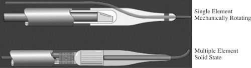 FIGURE 3C-3. Diagrams of typical single-element mechanically rotated and solid-state multiple transducer intravascular ultrasound catheters. |
Most commercially available mechanically rotating IVUS catheters operate at frequencies between 30 and 45 MHz with high axial resolution (80 to 100 μm).21,22 One of the main drawbacks of these devices currently is the lack of range dynamic focusing due to the single transducer element.22 The fixed-focus ultrasound imaging does not enable use of these devices with large peripheral vessels, which require a greater imaging depth.
Cylindrical Array Devices
Solid-state cylindrical transducer array devices comprise an array of PZT transducers that are mounted circumferentially around the distal end of a catheter body. Typical commercially available catheters have an array comprising 64 transducer elements (Fig. 3C-3). The individual transducer elements are operated sequentially to scan the ultrasound energy around the device. After each element or groups of elements have operated in “transmit mode,” they are then operated in “receive mode” to obtain backscatter information. The adjacent element or groups of elements then perform the same operation until the process has been completed through 360 degrees for the entire artery cross-section. A full scan of 360 degrees occurs approximately 30 times per second, resulting in a real-time image refresh rate similar to that of the mechanical IVUS devices.
The solid-state devices do not have any moving parts. As such, the construction of phased array devices does not include any air-filled voids, and therefore, their usage does not require saline flushing prior to or during usage. This aspect of the cylindrical array device operation greatly reduces the preparation time required prior to a procedure compared with that of the mechanical devices. The currently available solid-state devices operate at lower frequency compared to the mechanical devices. Hence, the axial resolution is somewhat compromised with the solid-state devices. However, electronic focusing is implemented with these devices, and the ultrasound energy can be focused at varying depths, favoring the array devices for imaging of both large and small vessels.
Operating Frequency
A key feature that sets IVUS devices aside from conventional noninvasive ultrasound devices is the operating frequency. Most external ultrasound imaging devices operate within 3 to 12 MHz. IVUS devices operate in the range of 12 to 50 MHz. The operating frequency has a major impact on two aspects of the IVUS images: (a) resolution, and (b) image depth. The resolving power of the IVUS system increases with the frequency of operation. The trade-off with increasing frequency is the depth of penetration in the vessel wall (see Fig. 3C-4). Therefore, the higher the frequency of ultrasound, the faster the backscatter is weakened as it propagates through tissue. The effect of this phenomenon is that high-frequency IVUS cannot penetrate far into the vessel wall and surrounding adventitia. The lack of penetration is usually not an issue in coronary arteries, since IVUS is used to visualize tissue that is relatively close to the transducer. However, this trade-off is apparent in instances where it is desirable to image very large peripheral arteries.
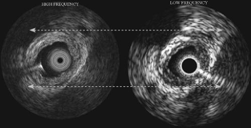 FIGURE 3C-4. Two intravascular ultrasound (IVUS) images of the same plaque (ex vivo) with IVUS catheters operating at high (left) and low (right) frequencies. The higher frequency image displays better resolution but lacks in depth of penetration, whereas the lower frequency image displays less resolution but one can observe information further out into the surrounding tissue. |
Atherosclerotic Tissue Characterization with Intravascular Ultrasound
Many studies have recognized the importance of IVUS in clinical assessment of atherosclerosis.1,25,28,29,30,31 Multiple efforts are underway to employ IVUS for gaining better understanding of:
Plaque/arterial wall mechanical properties (for review, see reference 40 or recent work by Tajaddini et al.41).
This chapter focuses mainly on techniques for determining plaque composition. Over approximately the past 15 years, extensive research has been conducted on image- and signal-based analysis methods for plaque characterization. The following sections describe some of these approaches, including their pros and cons. Finally, a description of the novel VH-IVUS technique is provided.
Image Analysis
Fibrous or “hard” plaques are generally advanced lesions that contain dense fibrous tissue, collagen and elastin fibers, and proteoglycans. Similar to calcified regions of plaque, dense fibrous plaque components reflect ultrasound energy well and
thus appear bright and homogeneous on IVUS images (see Fig. 3C-5).42 One of the major problems with many of the image-based studies is their dependence on plaque brightness as a discriminator of fibrous tissue content. This parameter is highly dependent on the gain setting of the IVUS console and its transmit power. Therefore, direct comparison of brightness in IVUS images acquired at different times may not be possible. In an attempt to overcome this problem, Hodgson et al. suggested comparing the echo reflectance of the plaque with that of the adventitial reflectance.28 Unfortunately, the signal produced by the adventitia may be significantly attenuated by the intervening tissue and consequently produce a dimmer image.
thus appear bright and homogeneous on IVUS images (see Fig. 3C-5).42 One of the major problems with many of the image-based studies is their dependence on plaque brightness as a discriminator of fibrous tissue content. This parameter is highly dependent on the gain setting of the IVUS console and its transmit power. Therefore, direct comparison of brightness in IVUS images acquired at different times may not be possible. In an attempt to overcome this problem, Hodgson et al. suggested comparing the echo reflectance of the plaque with that of the adventitial reflectance.28 Unfortunately, the signal produced by the adventitia may be significantly attenuated by the intervening tissue and consequently produce a dimmer image.
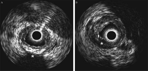 FIGURE 3C-5. Intravascular ultrasound images of diseased human coronary arteries, ex vivo. A: Calcified plaque distinguished by high echogenicity followed by a shadow (asterisk). B: (Asterisk) An echolucent region considered to be representative of a lipid-laden necrotic core. |
Lipidic or “soft” plaques have been implicated in acute ischemic syndromes such as plaque rupture. In IVUS images, regions of low echo reflectance are usually labeled soft plaque (Fig. 3C-5).28,43 Echolucent regions believed to be lipid pools were first reported by Mallery et al.44 and later by Potkin et al.42 In a similar study comparing ex vivo IVUS images to histology sections using 40-MHz transducers, IVUS detection of lipid deposits was shown to have a sensitivity of 88.9% and a specificity of 100%.45 However, this study did not demonstrate data comparing the size of lipid deposits in IVUS images with those in histology, nor was the vessel pressurized during pullback, making comparisons between the data sets difficult. In addition, this study utilized paraffin-embedded tissue, which requires dehydration and “clearing” stages that dissolve and elute lipid. In another study by Zhang et al., automated image processing techniques were applied to IVUS images captured from video in an attempt to classify lesions as soft plaque, hard plaque, or hard plaque with shadow (i.e., calcified).46 The technique’s performance was assessed by comparing the results with those determined by manual interpretation. Other IVUS image analysis studies with high-order, statistical texture-based algorithms have been shown to perform well in determining plaque.46,47,48,49 However, image-based analysis techniques are slow, and they are limited to offline processing.49
Backscatter Signal Analysis
Analysis of the ultrasound backscatter signals eliminates the need to postprocess the IVUS images and affords an entry to the important frequency information contained in the backscatter. Studies have shown that differentiation between vessel layers and tissue types is possible ex vivo.11,33,36,50,51


Stay updated, free articles. Join our Telegram channel
Full access? Get Clinical Tree
