Intracardiac Ultrasound
Jonathan S. Steinberg
Kataneh Maleki
Jayanthi Koneru
Farooq Chaudhry
Vascular-based ablation procedures require the accurate placement of catheters at target tissues to deliver ablative energy to interrupt arrhythmia circuits, create lines of block, or destroy triggering foci. Many contemporary ablation procedures depend less on mapped electrophysiologic recordings and instead on targeting the critical anatomic elements necessary for arrhythmia initiation or perpetuation. Traditional tools used for guiding catheters into proper target zones have been electrical recordings and fluoroscopic imaging. The latter of course provides at best only indirect information, as judged by catheter position in relationship to the imaged cardiac silhouette, known anatomic relationships, and ancillary local recordings. Another disadvantage is the risk of exposure to ionizing radiation for the patients, support staff, and electrophysiologist during prolonged or repeated procedures.
Intracardiac ultrasound (ICUS) is a relatively new EP imaging modality, fueled by the miniaturization of technical probe components with lower imaging frequencies and greater depth of field, which allows continuous safe direct ultrasonic visualization of natural cardiac structures and intravascular catheters, and for monitoring of unwanted complications, all online and instantaneous. These characteristics offer the potential to enhance the success and the safety of catheter ablation procedures, especially when complex like those designed for atrial fibrillation (AF).
ICUS uses a catheter-based ultrasound probe, which allows visualization of the heart from within the cardiac chambers or the great vessels. The imaging catheter is passed into the right heart chambers from the femoral vein. Over the years, ICUS catheters have become more miniaturized and image quality has improved dramatically from single element transducers to the current phased-array transducers. Newer transducers allow for higher resolution 2-D imaging with both pulse and continuous wave spectral Doppler and color Doppler imaging capabilities.
Other ultrasound methods were not as useful as ICUS. Transthoracic echocardiography is not helpful because it interferes with the sterile field, does not ideally image all patients and all important anatomic regions, and often requires technical assistance during prolonged procedures. Transesophageal echocardiography has been utilized in some EP laboratories but has the disadvantages of patient discomfort, need for anesthesia (sometimes prolonged), and often requires the assistance of an anesthesiologist and echocardiographer in the EP lab.
In this chapter, we describe the uses and advantages of ICUS, including accurate visualization of cardiac anatomy and endocardium, visualization of intracardiac catheters and devices, monitoring for complications, determination of hemodynamic function using Doppler features, reduction in ionizing radiation exposure, and simple vascular placement of probe suitable for prolonged procedures. Specifically, we detail the technical aspects of ICUS equipment, venous access, and ICUS catheter positioning; the value of ICUS-assisted transseptal puncture; use of ICUS to describe pulmonary vein (PV) and left atrial (LA) anatomy and function; the use of ICUS to position mapping and ablation catheters and for effective delivery of radiofrequency energy; and the early detection of serious complications and their treatment. Use of the ICUS modality for ablation procedures requires substantial experience and skill acquisition to maximize its clinical utility and allow the EP operator to function independently.
Historical Perspective
Historically there have been significant developments in ICUS, specifically in miniaturization and maneuverability of catheter and phase array electric crystal technology to optimize intracardiac imaging. Real-time M-mode echocardiography was used for intracardiac imaging as early as the late 1970s to the early 1980s (1,2). In 1990, intracardiac imaging using high-frequency transducers (20 MHz) with better resolution was developed but tissue penetration was limited and thus unacceptable (3). To overcome this, in the early 1990s, catheter-based imaging techniques using 12.5 MHz (6 F) and 10 MHz (10 F) mechanical devices were developed. Due to the lower frequencies of these transducers, the penetration to visualize distant cardiac structures improved with acceptable resolution (4,5).
The imaging frequency for ICUS was further reduced to 9 MHz (9 F catheters) (Boston Scientific Company, Watertown, MA), which improved the ultrasound penetration even further (6, 7, 8, 9, 10, 11). More recently, an electronic longitudinal phasedarray-based ultrasound catheter (10 F, 90 cm length), with a wide dynamic frequency range (5.5-10 MHz) and with both pulse and continuous wave spectral Doppler and color-flow imaging, was developed (AcuNav, Siemens Medical Solutions, Inc., Mountainview, CA) (Fig. 5.1). The AcuNav utilizes single-plane imaging, with a
single-use probe that can be connected to a standard ultrasound imaging system. The variable frequency, steerability, and flexibility of the probe provide both higher resolution and deeper penetration, and the ability to image most of the cardiac structures from the right atrium (RA), right ventricle, or inferior vena cava.
single-use probe that can be connected to a standard ultrasound imaging system. The variable frequency, steerability, and flexibility of the probe provide both higher resolution and deeper penetration, and the ability to image most of the cardiac structures from the right atrium (RA), right ventricle, or inferior vena cava.
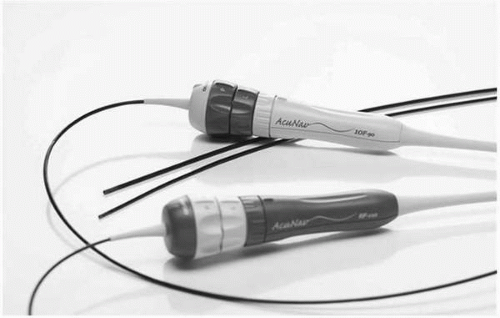 Figure 5.1. AcuNav phased-array ultrasound catheter with a dynamic range of 5.5 to 10 MHz with both pulse, continuous wave spectral Doppler and color-flow imaging. (Courtesy of Siemens Medical Solutions, Inc, Mountainview, CA.) |
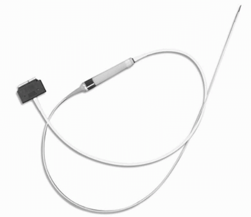 Figure 5.2. ViewFlex phased-array catheter with M-Mode, 2-D, spectral and color-flow Doppler imaging capability. (Courtesy of EP Medical Systems, West Berlin, NJ.) |
Similarly, the View Flex catheter (EP Medical Systems, West Berlin, NJ), a single-use 64-element linear phased-array (10 F, 110 cm length) imaging catheter with bidirectional steerability and M-mode, 2-D, spectral and color-flow Doppler, is also clinically available (Fig. 5.2).
Ultrasound Principles and Techniques
Ultrasound waves, as the name suggests, are sound waves with frequencies far above the upper limits of the normal range for human hearing (20 Hz-20 KHz) (Fig. 5.3). Image resolution and penetration of the ultrasound beam is based on the frequency of the imaging probe (Fig. 5.4). As the frequency of the transducer increases, the
resolution of the image improves but at the expense of decreased penetration (Fig. 5.5 and Table 5.1). Thus it is important to trade off resolution for penetration depending on which structures need to be imaged. For transthoracic (surface) echocardiography, for example, because penetration through the lungs and the rib cage is required, a lowerfrequency probe is used as compared with transesophageal or intracardiac echocardiography, where the penetration requirement is lower as the probe is positioned right behind the heart or within the cardiac chambers respectively. Understanding these basic concepts is important for any physician involved with ultrasound imaging.
resolution of the image improves but at the expense of decreased penetration (Fig. 5.5 and Table 5.1). Thus it is important to trade off resolution for penetration depending on which structures need to be imaged. For transthoracic (surface) echocardiography, for example, because penetration through the lungs and the rib cage is required, a lowerfrequency probe is used as compared with transesophageal or intracardiac echocardiography, where the penetration requirement is lower as the probe is positioned right behind the heart or within the cardiac chambers respectively. Understanding these basic concepts is important for any physician involved with ultrasound imaging.
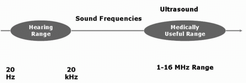 Figure 5.3. The normal hearing range of ultrasound frequency for the human ear is from 20 Hz to 20 kHz. Ultrasound frequencies used for imaging purposes are much higher (1 MHz-16 MHz). |
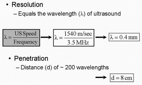 Figure 5.4. The resolution of an image at a specific frequency is determined by dividing the wavelength of the ultrasound beam (1540 m/sec, a constant) by the frequency of the imaging probe. In this example, using a 3.5 MHz probe, the resolution is 0.4 mm and the penetration is 8 cm, approximately 200 times the wavelength of the ultrasound. |
Although transesophageal echocardiography using multiple planes can provide excellent images and detailed intracardiac anatomy for increasingly complex interventional procedures, it has certain disadvantages when compared with intracardiac echocardiography. The transesophageal echo requires prolonged placement of the probe in the esophagus, which requires significant sedation and/or general anesthesia resulting in significant discomfort to the patient from prolonged intubation, thus limiting its role in interventional procedures. Furthermore, the images obtained by the current longitudinal phased-array ICUS can provide comparable images to transesophageal echocardiography, especially of the left heart, the interatrial septum, the valves, and the pulmonary veins (PVs). Due to the variable ultrasound frequency of the ICUS probe (5.5-10 MHz), images of distant structures can be captured with greater detail even in patients with enlarged hearts. Furthermore, Doppler and color-flow imaging for the atrium, ventricles, valves, and great vessels can be easily obtained. With intracardiac echocardiography the catheter is positioned in the RA during the entire procedure with excellent patient tolerance (12, 13, 14, 15, 16).
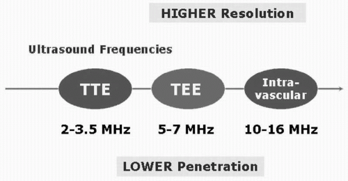 Figure 5.5. As the frequency of the transducer is increased, the resolution improves but penetration decreases. Thus, depending on which structure needs to be imaged, resolution and penetration need to be balanced for optimal image acquisition. |
TABLE 5.1 Resolution versus Penetration | ||||||||||||||||||||||||||||
|---|---|---|---|---|---|---|---|---|---|---|---|---|---|---|---|---|---|---|---|---|---|---|---|---|---|---|---|---|
|
Limitations
The major limitations of ICUS are the risk of an invasive procedure and the significant cost of single-use disposable ICUS catheters. As the catheter sits within the RA, the near field may be difficult to visualize. However, this can be overcome by manipulating the catheter. There is also a learning curve for catheter manipulation to obtain views of the cardiac structures outlined below.
ICUS is increasingly used to assist in invasive cardiac procedures, specifically in the cardiac catheterization and electrophysiological laboratories. The intracardiac catheter is typically inserted via a femoral venous sheath and advanced to the RA using fluoroscopy to guide accurate placement as the probe does not accommodate a guide wire system. The intracardiac echo probe can then be manipulated to acquire different views by advancing, withdrawing, and rotating the probe similar to monoplane transesophageal imaging. Furthermore, the tip of the probe can be flexed or tilted using dials at the base of the probe to further optimize the imaging planes (Fig. 5.6). From the RA location, multiple critical structures are readily imaged, including the tricuspid valve and the right ventricle, the mitral valve and the left ventricle, the short axis of the aortic valve, the interatrial septum, and the LA and the PVs.
In all these views, 2-D measurements as well as pulse and continuous wave spectral Doppler and color Doppler measurements can be obtained. The probe can be further advanced into the right ventricle to view the right ventricle outflow tract and the pulmonary artery as well as imaging the left ventricle for assessing regional and global wall motion. If the probe is pulled further back to the inferior vena cava (IVC), the abdominal aorta can be readily visualized.
The 10 F ultrasound catheter is introduced through an 11 F sheath inserted in the femoral vein, and advanced to the RA. Upon entry in the RA, the probe is positioned in the mid-RA in a neutral position, 1 to 2 cm above the IVC/RA junction. This position (Fig. 5.7) will be a common start point for many of the anatomical destinations used in the electrophysiology laboratory.
From the mid-RA, the catheter can be rotated very slightly clockwise, and the interatrial septum will begin to appear. An imaging frequency of 8.5 MHz is optimal. Some posterior deflection may be required. The septum has a thicker area (limbus) and a thinner area, the fossa ovalis. By further clockwise rotation, the left atrial appendage (LAA) will be visualized (Fig. 5.8). Sometimes it is difficult to distinguish the LAA from the left superior PV, and if so, pulsed wave or color Doppler can help differentiate the two structures. Imaging the LAA and the left PVs is facilitated by a frequency of 5.5 to 7.5 MHz. If the catheter is rotated clockwise slightly, the left PVs are visualized. From this position, the left common PV can be differentiated from two separate PVs (upper and lower) (Fig. 5.9). If the junction between the upper and lower PVs joins the plane of the LA wall, two separate left PVs are defined; if the junction falls short of the plane of the LA wall, a common trunk is defined. This differentiation is very important because the ablation strategies will be based on this information. While imaging the left PV(s), pulsed wave Doppler and color flow can be obtained to confirm venous structures from LAA. Subtle clockwise/counterclockwise rotation may be necessary to obtain images of each PV and the LAA. The left PVs can usually be seen in their long axis.
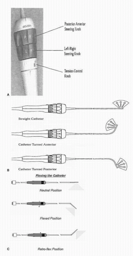 Figure 5.6. A: The AcuNav catheter has two steerable knobs; a posterior-anterior knob (P&A) and a left-right knob (L&R). Steerable knobs allow you to bend the tip of the catheter during imaging for acquisition of different imaging planes. B: The imaging face of the AcuNav catheter faces anteriorly and the scanning plane is longitudinal. The catheter can be steered anteriorly/posteriorly or left to right by maneuvering the respective knobs. C: The ViewFlex catheter offers a bidirectional curve with a deflection angle of up to 60°. The neutral position is obtained by aligning to the white line on the catheter knob. The flexed position is obtained by turning the catheter knob clockwise. The retroflexed position is obtained by turning the catheter knob counterclockwise. |
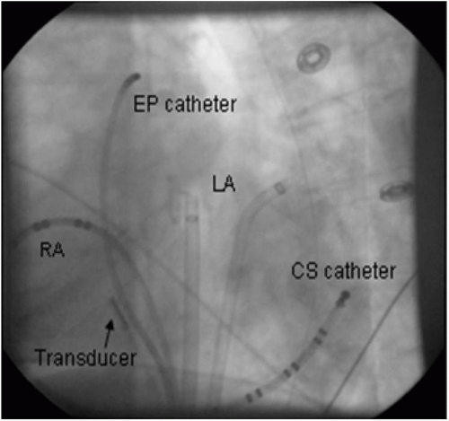 Figure 5.7. Fluoroscopic image demonstrating ultrasound transducer in the mid-right atrium (RA) in LAO view. Left atrium (LA) and coronary sinus (CS) sheaths and catheters are also shown. |
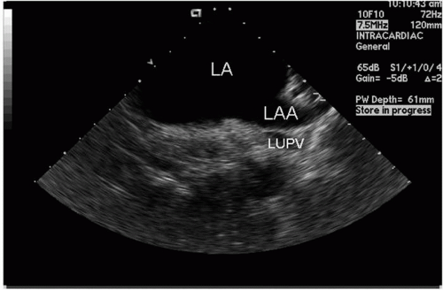 Figure 5.8. Left atrial appendage (LAA) and adjacent left atrium (LA) recorded from the transducer positioned in the mid-right atrium; part of the left upper pulmonary vein (LUPV) is also seen. |
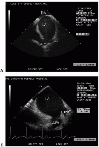 Figure 5.9. A: Image recorded with the probe near fossa ovalis in right atrium (RA), showing left atrium (LA) with a common left-sided pulmonary vein (orifice delineated by “+” signs) with left lower pulmonary vein (LLPV) and left upper pulmonary vein (LUPV). B: Independent left lower (LLPV) and left upper(LUPV) veins emptying into left atrium (LA). |
When the catheter is in the mid-RA and is rotated more posteriorly, the right PVs are identified in sagittal view. They may look like “owl’s eyes” in the near field of the image (Fig. 5.10). Sometimes, the right superior PV is located more posteriorly and imaging of this vein can be more challenging; therefore, advancing the catheter to the junction of superior vena cava (SVC)/RA or SVC and anterior flexion of the catheter can help visualize this structure. The right inferior PV usually can be visualized in its long axis but the RSPV is often more difficult.
The diameter of each PV can be measured at the LA-PV junction from leading edge to edge. Color and pulsed wave Doppler information can be recorded to qualify venous flow. Pulsed wave Doppler tracings are performed by obtaining a sample volume 1 to 2 cm into the mouth of the PV. The typical tracing in sinus rhythm has three components: the forward flow components represent systole (S) and diastole (D), and a retrograde flow represents atrial contraction (AR) (Fig. 5.11).
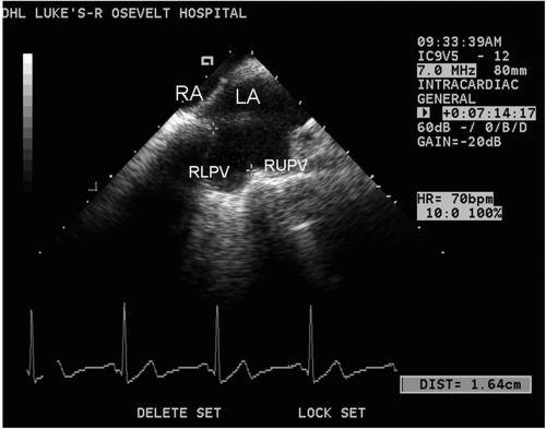 Figure 5.10. Image recorded with the probe in high right atrium (RA), showing right upper (RUPV) and right lower (RLPV) pulmonary veins simultaneously and adjacent left atrium (LA). |
Transseptal catheterization is a procedure performed to gain access to the LA and occasionally the left ventricle. It was commonly used in cardiac catheterization laboratories prior to the advent of retrograde left heart catheterization. However,
technological advances and refinement in the techniques of left heart catheterization made this procedure virtually obsolete in many catheterization laboratories until the recent past.
technological advances and refinement in the techniques of left heart catheterization made this procedure virtually obsolete in many catheterization laboratories until the recent past.
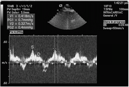 Figure 5.11. Pulsed Doppler velocity signals recorded with transducer in right atrium with sampling volume in ostium of the RLPV prior to ablation, showing peak flow velocity during systole (S) as well as flow during diastole (D) and atrial reversal (Ar). |
Transseptal catheterization has been employed more consistently in the electrophysiology laboratory to gain access to the left side of the heart and initially to ablate left-sided accessory pathways and other LA foci or arrhythmogenic circuits. Because catheter ablation of AF has become an increasingly important therapy in recent years, transseptal procedures have become a mainstay in many labs. Transseptal catheterization is performed by accessing the LA from the RA by crossing through the fossa ovalis. In approximately 10% to 15% of patients, this maneuver is performed via a probe-patent foramen ovale (17). In the remainder, mechanical puncture of this area with a needle and catheter combination is required to enter the LA. Transseptal puncture is safe but an inherent danger of this procedure is the potential of the catheter or the needle to puncture adjacent structures. These include the posterior wall of the RA, the coronary sinus, the aortic root, or the posterior wall of the LA. Inadvertent puncture of any of these structures is a dreaded and potentially deadly complication especially when anticoagulant therapy is started. Other complications of transseptal puncture include systemic arterial embolism and perforation of the inferior caval vein. Herein lies the importance of utmost accuracy in identifying the regional anatomy of the atrial septum. This regional anatomy may vary depending on the underlying structural disease in an individual patient.
Traditionally, localization of the fossa ovalis was achieved by fluoroscopy. However, fluoroscopy-guided anatomic localization for electrophysiological procedures suffers from certain drawbacks. They include failure to identify the endocardium and the anatomic detail required for catheter positioning. Transthoracic echo and TEE have also been reported to be useful in guiding transseptal puncture; however, there are limitations to both imaging modalities. Traditional transthoracic echocardiogram is suboptimal for the visualization of the interatrial septum. Furthermore, the placement of the transducer on the patient’s chest interferes with the fluoroscopic images. TEE is a semiinvasive tool that requires considerable sedation and increases the risk of lung aspiration, stress to the patient, and esophageal injury. The advent of ICUS has vastly simplified transseptal access during electrophysiological procedures and can supplant other imaging modalities.
Transseptal Technique
We recommend a phased-array ultrasound catheter, which consists of a miniaturized 64-element, phased-array transducer, incorporated in a single-use catheter. The transducer scans in the longitudinal monoplane, providing a 90° sector image with tissue penetration of up to 15 cm. The latter makes imaging of the LA from RA position feasible. Two planes of bidirectional steering (anterior-posterior and left-right, each to an extent of 160°) are possible. The high-resolution multiple frequency transducer (5.5-10 MHz) allows tissue penetration enhancement, and thus depth control. Measurements of hemodynamic and physiologic variables can be made using Doppler imaging. The catheter is connected to a standard console.
The classic approach for transseptal catheterization is from the right femoral vein, although left femoral vein and transjugular approaches have been described. The ICUS images are displayed on a monitor and can be recorded on videotape or on the system’s hard drive. A transseptal sheath (for example, SL1 or Agillis; Daig Corp, St Paul, MN) is introduced via the femoral vein and guided to the SVC over an introducer wire. The transseptal sheath is loaded with a Brockenbrough needle (Daig
Corp), which is advanced to within 1 cm of the dilator tip. We typically monitor the position of the sheath in two fluoroscopy planes—anteroposterior and left anterior oblique. The ICUS catheter is positioned in the mid-RA, providing a clear view of the interatrial septum (see above). The septum consists of a thicker part, the limbus, and the remains of the primary atrial septum, the fossa ovalis, which is the safest target for the transseptal puncture. The ICUS catheter is moved slightly to gain a full view of the fossa in the center (Fig. 5.12). Some posterior deflection of the ICUS catheter might be required. The fossa ovalis is clearly delineated, and its size, length, and proximity to the LA wall are noted, along with the presence or absence of any LA thrombus. Interatrial septal aneurysm can be visualized, if present. If abnormal or variant patient anatomy does not easily allow optimal ICUS catheter positioning, an angled sheath can be advanced and torqued to bring the ICUS catheter into the correct position.
Corp), which is advanced to within 1 cm of the dilator tip. We typically monitor the position of the sheath in two fluoroscopy planes—anteroposterior and left anterior oblique. The ICUS catheter is positioned in the mid-RA, providing a clear view of the interatrial septum (see above). The septum consists of a thicker part, the limbus, and the remains of the primary atrial septum, the fossa ovalis, which is the safest target for the transseptal puncture. The ICUS catheter is moved slightly to gain a full view of the fossa in the center (Fig. 5.12). Some posterior deflection of the ICUS catheter might be required. The fossa ovalis is clearly delineated, and its size, length, and proximity to the LA wall are noted, along with the presence or absence of any LA thrombus. Interatrial septal aneurysm can be visualized, if present. If abnormal or variant patient anatomy does not easily allow optimal ICUS catheter positioning, an angled sheath can be advanced and torqued to bring the ICUS catheter into the correct position.
Stay updated, free articles. Join our Telegram channel

Full access? Get Clinical Tree


