Fig. 2.1
Adult multiplane transesophageal echocardiography transducers (on the left) and pediatric biplane transducers. (on the right) available 10–15 years ago
In the last 10 years, multiplane TEE probes have become widely available for both adult and pediatric patients, allowing stepwise study of an area of interest by fine mechanical or electronic rotation of the scanning plane through 180° [12–17]. With advances in technology, multiplane TEE probes have gradually decreased in size from 16 to 14, to 13, 10, and even 7.5 mm. These devices include phased array technology, with the array on a rotating turntable at the tip of the probe engineered to steer the ultrasound-examining plane through a 180° arc. This technology effectively provides a 360° “panoramic” image of the heart, but requires a flexible ribbon connector to the array probe to allow its rotation. All standard echocardiographic modalities discussed, including M-mode, color flow Doppler imaging, spectral Doppler (pulse and continuous wave), and color M-mode, typically can be obtained with a modern multiplane transesophageal scanner.
Probes for TEE
The early TEE probes were actually modified gastroscopes with fiberoptic visualization and suction ports. In contrast, modern transesophageal probes have been specifically manufactured for echocardiographic purposes only. The ultrasound beam is propagated from the transducer and the returning signals are processed in a manner identical to that used for transthoracic echocardiography. However, the transducer face is smaller than the transthoracic probe and there are fewer channels available for transmission.
The modern TEE probes cover multiple frequencies, typically ranging from 3 to 10 MHz. Today, all adult TEE probes as well as the smaller pediatric TEE probes are fully equipped with two-dimensional imaging, M-mode, and complete Doppler capabilities. In view of the unobstructed window for interrogation and the intrinsically high frequencies, the potential benefit of tissue harmonic imaging for TEE is probably less than that for transthoracic imaging. Table 2.1 gives a summary of the most widely available pediatric and adult size TEE probes in North America, including selected probe information, produced by the three largest echocardiography manufacturers.
Table 2.1
Currently available transesophageal echocardiography probes (adult and pediatric)
Tip dimensions (Width × Height × Length, mm) | Shaft dimensions (Width × Length, mm) | Number of elements | Imaging frequencies (MHz) | |
|---|---|---|---|---|
Philips (Hewlett Packard/Agilent) | ||||
Pediatric biplane (21366A) | 9.3 × 8.8 × 27 | 8 × 80 | 64 | 5.5–7.5 |
Pediatric mini-multiplane (T6207/S7–3t) | 10.7 × 7.2 × 25.4 | 7.4 × 70 | 48 | 4.0–7.0 |
Pediatric micro-multiplane (S8–3t) | 7.5 × 5.5 × 18.5 | 5.2 × 85 | 32 | 3.0–8.0 |
Adult multiplane (Omni III) | 14.5 × 11.2 × 42 | 10.5 × 100 | 64 | 4.0–7.0 |
Adult 3D TEE (X7–2t) | 16 × 12 × 40 | 10 × 106 | 2,500+ (Matrix) | 2.0–7.0 |
Siemens (Acuson) | ||||
Pediatric biplane (V7B) | 9.5 × 8.5 × 31 | 8.5 × 85 | 48 | 5.0–8.0 |
Pediatric mini-multiplane (V7M) | 10.7 × 7.2 × 25.4 | 7.4 × 70 | 48 | 4.0–8.0 |
Adult multiplane (V5M) | 14.5 × 11.5 × 45 | 10.5 × 110 | 64 | 3.5–7.0 |
General electric (Vingmed) | ||||
Pediatric multiplane (9T, MPTE, 9Tc/9T-RS) | 10.9 × 8.4 × 35.2 | 7 × 70 | 48 | 3.0–10.0 |
Adult multiplane (6T/6TV, 6Tc-RS/6Tc-RS) | 14 × 12.5 × 45 | 10.5 × 110 | 64 | 3–8.0 |
Adult 4D TEE (6VT-D)* | 14.3 × 12.7 × 45 | 10.5 × 110 | 2,500 (Matrix) | 3.0–8.0 |
The pediatric TEE probes provide high frequency, high quality imaging. Their small size and greater probe flexibility make them well suited for use in children and infants; however the same features so advantageous for the pediatric age group can limit their usefulness in adults. Specifically, the smaller probe size and greater flexibility can lead to difficulty maintaining constant wall contact in a larger (adult-size) esophagus, and the higher probe frequencies can reduce the effective depth useful for two-dimensional and color flow Doppler imaging. For these reasons, the pediatric TEE probes have limited utility in adult patients, though in some adults they can be used to image structures in the near to mid field [18].
History of TEE Probe Development for Children
The 1982 report of the first phased array TEE probe by Hanrath’s group included an example of an ostium secundum atrial septal defect [6]. Nonetheless, in its early stages the application of TEE for evaluation of CHD was limited due to several factors: (a) the large sizes of the early TEE probes precluded their use in patients less than 20 kg, i.e. infants and children in whom the vast majority of cardiac disease was congenital; (b) color flow and spectral Doppler evaluation, integral tools for CHD evaluation, were not yet available; (c) only a single TEE plane could be used, limiting optimal visualization of a number of cardiac structures. It was only after important technological advances in TEE probe and imaging technology in the late 1980s and early 1990s that the use of TEE for evaluation of CHD began to grow. Following the availability of higher resolution imaging and color flow Doppler mapping, Sutherland and colleagues [19] as well as other investigators [20, 21] demonstrated the ability of TEE to evaluate CHD using an adult size TEE probe. However the use of TEE for CHD evaluation remained limited until the development of a smaller TEE probe that could be used in pediatric size patients.
Single-Plane Probes
Single-plane TEE for pediatric patients was developed in the late 1980s. The first transesophageal probe for use in children, developed in 1988 by Omoto and colleagues, consisted of a single-plane, phased array, 24 element, 5 MHz unit mounted on an pediatric gastroscope measuring 6.8 mm in diameter [22]. This TEE probe produced a single, transverse scan plane and could only be used in patients who weighed more than 3.0 kg [23]. However, single plane TEE for pediatric patients was superseded by the rapid technological advances in the 1990s that made possible the development of small biplane and multiplane transesophageal probes appropriate for use in infants and small children with CHD [24–26].
Biplane Probes
In the biplane transesophageal probe for children, there are two sets of transducers, 48 × 48 or 64 × 64 elements mounted perpendicular to each other, one above the other, at the tip of the probe (Fig. 2.2). The centers of the transverse palette and the longitudinal palette are separated by less 1.0 cm depending upon the transducer size. Commercially available biplane transesophageal probes are about 7–10 mm in diameter. With biplane transesophageal imaging, one transducer set imaged in a transverse plane (0°), the other set imaged in a longitudinal scan plane (90°) orthogonal to the transverse plane. For these probes, the patients needed to weigh more than 3.0 kg as well, similar to single-plane probes [27–29]. While biplane adult TEE probes are no longer actively used (having been replaced by multiplane TEE probes), pediatric biplane probes are still available and used in some institutions. In some instances, these probes can be used when the slightly larger mini-multiplane probe (discussed below) cannot be inserted into the esophagus.
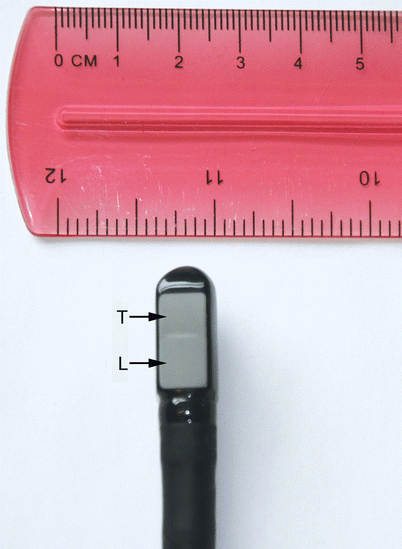

Fig. 2.2
Pediatric biplane probe tip. There are two sets of transducers, each imaging in a separate plane. The transverse plane (T) images at 0°, the longitudinal plane (L) at 90°, thus the two planes are orthogonal to each other
Multiplane Probes
Multiplane transesophageal transducer technology consists of a single array of crystals that is electronically or mechanically rotated about the long axis of the sound beam in a 180° arc, producing a circular continuum of tomographic, two-dimensional images [30]. Multiplane TEE probes were first introduced in early 1990s [12, 13, 16, 17]. Because of the 64 imaging elements and cabling needed to generate multiplane imaging, the early multiplane TEE probes were large, with diameters anywhere from 14 to 18 mm (Fig. 2.3), which limited their use to pediatric patients who weighed more than 20–30 kg (or even larger). Continued technological improvements, however, soon led to the development of multiplane TEE transducers suitable for small children, infants, and even neonates.
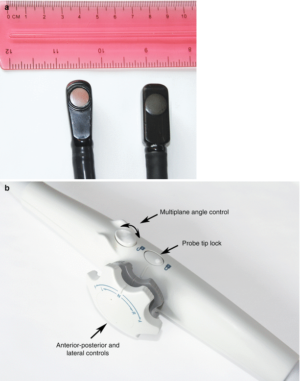

Fig. 2.3
Adult multiplane probes, tip and handle. (a) Shows two adult multiplane transesophageal echocardiography transducers. There is a single array of crystals that can be rotated in a 180° arc. Note that the large size of these transducers precludes their use in children under 20–25 kg. (b) Shows the probe handle, which includes controls for probe tip movements (anterior-posterior, right-left), multiplane angle rotation, and locking of the probe tip (one of the two probe tip locks on this probe is located on the other side of handle, and therefore not visible on this photograph)
Mini-multiplane
With the evolving approach of pediatric cardiac surgery to perform one-stage repairs in newborns or infants with CHD under the age of 3 months, the need for smaller TEE probes became clear and compelling. In the early 1990s, Dr. Charles Lancée of Erasmus University in Rotterdam and his team produced a prototype of a mini-multiplane TEE probe [31]. It involved 48 elements, 5 MHz and the smallest introduction diameter of 9.5–10 mm. This device subsequently went into original equipment manufacturer distribution, and was used by GE/VingMed, Philips, and Siemens (Fig. 2.4) as their main pediatric TEE product. It remains the mainstay of the pediatric TEE imaging systems for both Philips and Siemens (GE subsequently developed its own pediatric multiplane probe). This mini-multiplane probe produces very high quality images, and it can be used in weight ranges down to about 2.5–3.0 kg, which is adequate for many 90–95 % neonates requiring surgery (although some have used it successfully in neonates down to 2 kg in weight). For diagnosis and post-operative evaluation, the mini-multiplane was a liberating invention for neonates and infants with CHD (Figs. 2.5, 2.6, and 2.7). Its efficacy and durability have been documented in multiple studies, and it remains, up to the time of this writing, the predominant pediatric multiplane TEE probe in use [32, 33].
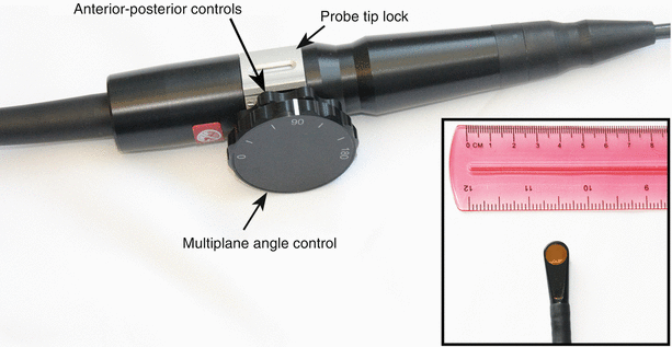
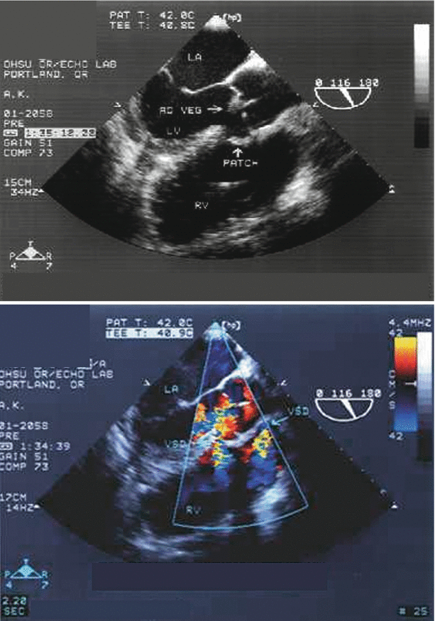
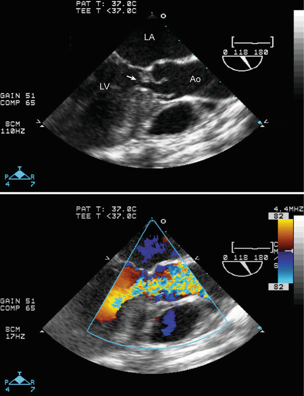
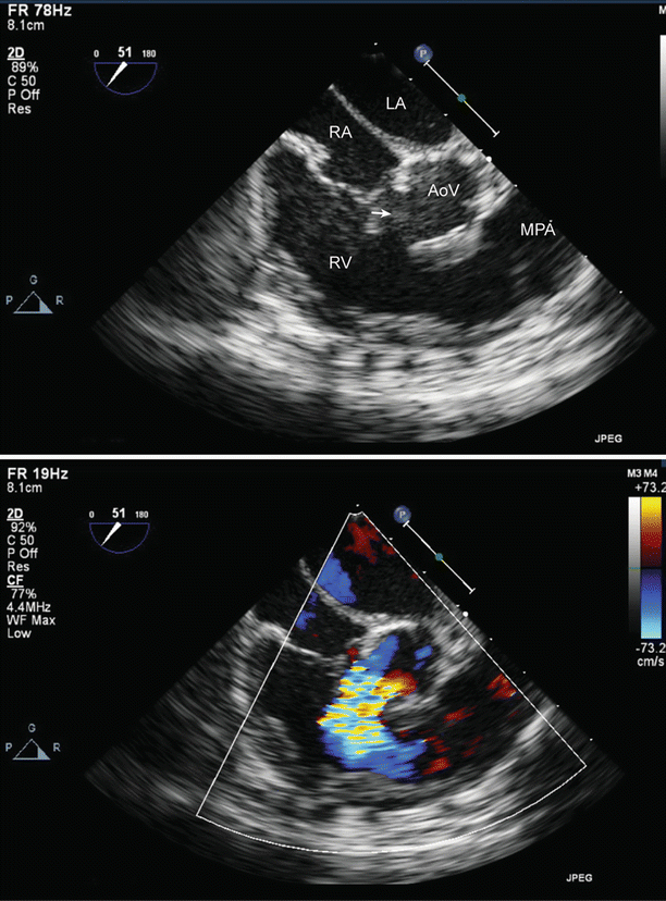

Fig. 2.4
Mini-multiplane transesophageal echocardiography probe and handle. The small probe size (inset) allows it to be inserted into neonates and young infants. The single array of crystals is rotated manually (mechanically) using the large outer dial, enabling adjustment of multiplane angle between 0° and 180°. The probe can flex only in an anterior-posterior direction, using the inner dial on the handle; lateral controls are not available on this probe. The probe tip can be locked/unlocked by the silver latch (shown in the diagram)

Fig. 2.5
Aortic valve endocarditis with subaortic ventricular septal defect (VSD), as seen from the mid esophageal aortic valve long axis view. This patient had undergone patch closure of the VSD. A vegetation is present on the aortic valve (top panel), and color flow Doppler shows a small amount of aortic valve regurgitation (bottom panel). In addition, a small residual VSD is seen at the inferior margin of the patch. Ao veg vegetation on aortic valve, LA left atrium, LV left ventricle, RV right ventricle

Fig. 2.6
Subaortic stenosis, as viewed with a preoperative transesophageal echocardiogram, using a mid esophageal aortic valve long axis view. Marked fibromuscular subaortic narrowing (arrow) is noted just below the aortic valve. There is also considerable ventricular septal hypertrophy (top panel). Color flow Doppler shows aliasing that begins at subaortic level (bottom panel). Ao ascending aorta, LA left atrium, LV left ventricle

Fig. 2.7
Large perimembranous ventricular septal defect (VSD), as noted from a modified right ventricular inflow-outflow view, multiplane angle 51°. A large ventricular septal defect is seen in the top panel (arrow). Left to right shunting is shown across the VSD by color Doppler (bottom panel). AoV aortic valve, LA left atrium, MPA main pulmonary artery, RA right atrium, RV right ventricle
Micro-multiplane
If one were to design a multiplane TEE probe that could safely be used in a wide range of neonates of different weights, what might be its specifications? The ideal device would be 7.5 MHz, and 8 mm or smaller, to allow safe probe placement even in neonates under 2 kg. It was on this basis that the high frequency array technology was developed, eventually becoming the micro-multiplane TEE probe. The micro-multiplane TEE probe, however, sets a specification of element size at 100-μm spacing and interconnects density in order to wire the array. This requires technology to achieve an adequate yield rate for 85 % or more of array pallets to be incorporated successfully into fully wired TEE probes, and to maintain their integrity for more than 2 years. As such, the specifications of the micro-multiplane TEE probe are a 6 MHz center frequency, 32 elements and 7.5 mm maximum tip diameter (Fig. 2.8). The probe offers full TEE ultrasound capabilities, including 2D imaging, color flow, pulsed and continuous wave Doppler, M-mode and color flow M-mode. It can be placed in very small neonates and young infants, and offers high quality imaging, as documented in studies interfacing this device with several different echocardiographic systems (Figs. 2.9 and 2.10) [34].
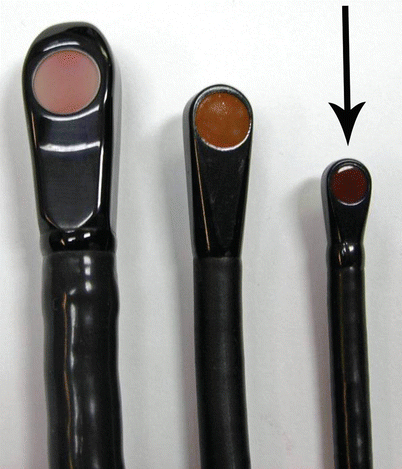
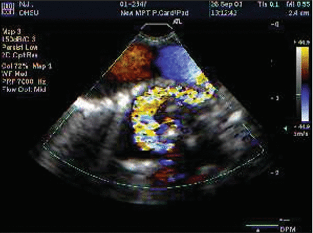
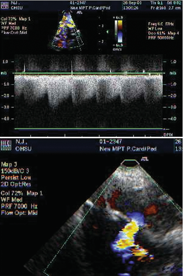
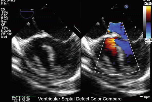

Fig. 2.8
Comparison of three different sized TEE probes. Adult multiplane (omniplane) 14.5 mm probe on the left, compared with a mini-multiplane 9.5 mm probe (center) and micro-multiplane 7.5 mm probe on the right (arrow). All three probes interface with the same echocardiographic platform from a single vendor


Fig. 2.9
Pulmonary atresia with ventricular septal defect. Intraoperative imaging of bronchial collateral vessels, by color Doppler (top panel), spectral assessment (middle panel), and evaluation of flow across a secundum atrial septal defect (bottom panel) using the micro-multiplane probe

Fig. 2.10
Ventricular septal defect viewed from mid esophageal four chamber view. These images were obtained with the micro-multiplane probe
Most believe that the mini-multiplane is small enough for pediatric TEE; but when the mini- and the micro-multiplane are viewed together, it is clearly and truly amazing what miniaturization has achieved with the micro-multiplane TEE probe. Figure 2.8 shows the relative sizes of three available multiplane probes: the micro-multiplane (arrow) next to the pediatric mini-multiplane and the adult multiplane (omniplane) probe. Several studies have validated the use of this probe in neonates weighing 2.5 kg [35–37]; some authors have reported successful use of the probe in patients as small as 1.7 kg [36]. Currently the micro-multiplane probe interfaces with only one echocardiography platform.
Clinical Experience—TEE for Children with CHD
In the early clinical experience with TEE for pediatric CHD patients, the major challenge was the lack of probes suitable for use in small infants. The first small probes used in children with CHD in the intraoperative setting were made available through Professor Ryozo Omoto [9]. These were single or biplane devices of 7 mm tip width. Maximal introduction diameter for these was kept up to 7 mm, with 24 × 24 or 32 × 32 element biplane configurations. Once multiplane imaging became available, it was obvious, from the feedback of our adult cardiology colleagues, that multiplane imaging provided flexibility that would be especially important in the TEE evaluation of CHD [38–40]. Early work with epicardial scanning by surgeons and subsequent TEE imaging during surgery for CHD demonstrated that intraoperative echocardiography positively affected patient outcome [41–44].
Over the past 20 years, the utility of TEE in the pediatric patient with congenital and acquired pathology has been well documented [32, 45–51]. Nonetheless despite the fact that TEE provides excellent detail of cardiac anatomy and hemodynamics in pediatric patients, the indications for TEE are more limited in scope, due to its semi-invasive nature [52, 53]. The most common application of TEE in children is for monitoring surgical and interventional procedures in CHD (see Chap. 3).
Multiple studies have documented the benefits of intraoperative TEE for surgical correction or palliation of CHD, noting its ability to alter patient management by visualizing virtually all areas of the heart, thereby allowing a highly accurate diagnosis for the majority of anatomic cardiac problems [54–57]. The benefits of intraoperative TEE include: (1) identification of additional anatomic or other diagnostic information preoperatively that alters the surgical repair or approach; (2) identification of significant residual anatomic abnormalities postoperatively that require additional surgical intervention, often with a return to cardiopulmonary bypass; and (3) identification of postoperative functional abnormalities, which require additional medical support, re-initiation of cardiopulmonary bypass, or use of other devices to support the circulation [58].
The combination of high resolution scanning and unobstructed visualization make TEE an ideal technique for identifying fine anatomic detail such as small congenital cardiac defects, valve chordae, vegetations in patients with suspected endocarditis, left atrial appendage thrombus, and evaluation of the thoracic portions of the aorta. As noted above, TEE serves as an important intraoperative tool to review the patient’s anatomy just prior to the surgical procedure, and an immediate reassurance to the surgeon of a good repair [59]. In addition to surgical intervention of patients for CHD, TEE has also been beneficial for interventional procedures in the cardiac catheterization laboratory [60], especially for those patients undergoing catheter-delivered atrial septal defect closure devices [51, 61–63], and ventricular septal defect closure either by transcatheter delivery [64–68] or by perventricular approach [69–73].
Three-Dimensional TEE
The early steps toward three-dimensional (3D) TEE are found in works by Steve Smith, Olaf von Ramm, Hanrath and Moser from Freiburg [74]. Initially 3D echocardiography relied upon a reconstructive approach, in which a sequential set of 2D tomographic planes was obtained using defined, discrete, incremental changes in the position of the image plane. The data from these planes was then reassembled into a 3D volume dataset, from which a volume-rendered 3D image could be extracted, as well as other user-defined 2D tomographic planes [75]. The reconstructive method capitalized on the rotational ability of the multiplane TEE transducer and the electronic steering of the rotating array. From the transesophageal approach, the probe position remained fixed, and the planar array was automatically rotated forward by 2–5° increments; at each increment new imaging data were collected. After a full stepwise collection of data through 180°, the images were assembled offline into a 3D, cone-shaped dataset, from which a 3D rendering could be generated of the cardiac structures within the dataset. It was obviously important that the transducer position and orientation within the esophagus remain absolutely stable. Even a slight motion of the transducer, due either to patient or operator motion, resulted in marked deterioration of imaging quality. Typically, 3–7 min were required to obtain a complete 3D dataset with this approach. For 3D echocardiography obtained via transthoracic imaging, a similar approach was undertaken by mounting the rotating TEE probe on a handheld transthoracic device that could be used to acquire a 3D dataset in exactly the same manner as that for 2D TEE.
In the early 2000s, real-time 3D echocardiographic imaging was introduced; initially this technology was available only for transthoracic transducers [76, 77]. However in 2007 a real-time 3D TEE probe (X7–2t, Philips Medical Systems, Andover, Massachusetts) became available for clinical use [78]. This 3D TEE probe provides a real-time, 3D display of cardiac anatomy, along with all of the modalities mentioned above including standard 2D imaging, spectral and color flow Doppler, M-mode, and Doppler tissue imaging (Fig. 2.11). The method of acquisition of 3D echocardiographic data is volumetric imaging. The transducer is constructed with a matrix array of transmitting and receiving crystals in a square grid, containing a total of about 2,500 elements. This allows for collection of a pyramidal image data set. This new generation ultrasound platform provides a true, real-time 3D image. For acquisition of a complete volume of cardiac data, sequential cardiac cycles (from 4 to 7) are typically captured and added together (“stitched”) to create a complete volume of information for full volumetric scanning [79, 80]. However, newer software allows acquisition of a full volume while performing live 3D imaging; this is known as “single beat” full volume scanning, and does not require ECG-gating. The development of 3D TEE is increasing: recently, a second adult-sized 3D TEE probe has been introduced as part of another cardiac ultrasound platform (6VT-D as part of Vivid E9 BT-12 system, GE Healthcare, Wauwatosa, Wisconsin) (Fig. 2.12).
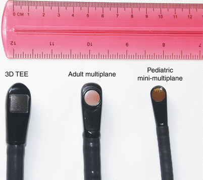
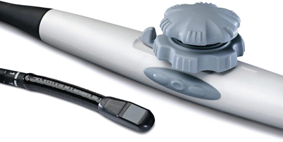

Fig. 2.11
Three-dimensional transesophageal echocardiography (3D TEE) probe on left, compared side by side with an adult two-dimensional (2D) multiplane probe (center), and pediatric mini-multiplane probe (right). Despite the fact that the 3D TEE matrix array has over 2,500 elements, the probe size is not much larger than the standard 2D adult multiplane probe (All probes from Philips Healthcare, Andover, Massachusetts)

Fig. 2.12
Four-dimensional transesophageal echocardiography recently introduced by GE Healthcare, as part of the Vivid E9 BT-12 cardiac ultrasound system. Like the 3D TEE probe shown in Fig. 2.11, this TEE probe also has a matrix array containing 2,500 elements (Photograph courtesy of GE Healthcare, used with permission)
Currently, 3D echocardiography is the newest TEE technology available. The new generation real-time 3D TEE probes avoids, the intermediate steps of “image reconstruction” and provide the option for simultaneous acquisition of true real-time biplane 2D imaging (X-plane). Although 2D TEE is still the predominant form of imaging used clinically, 3D provides a more complete spatial orientation. The additive value of 3D TEE has been well-documented in the evaluation of atrioventricular and semilunar valve disease in adult patients [81–85]. In addition, it can prove useful for identification of small ventricular septal defects, assessment of the size of an atrial septal defect, and creation of imaging planes that are not feasible using standard 2D imaging–such as an en face view of the atrial septum for visualization of the fossa ovalis or an atrial septal defect (See Chaps. 19 and 20). Quantitative accuracy for chamber volume determination is greater for 3D than 2D echocardiography. Because it avoids geometric assumptions, 3D echocardiography is particularly advantageous for the quantification of ventricular volume and function for the irregularly shaped right ventricle or abnormal left ventricle [79].
The major advantages for 3D TEE in CHD are best realized during interventional procedures involving atrial and ventricular septal defects, as well as for the evaluation of complex congenital abnormalities [86–90]. The use of 3D can provide novel views and imaging perspectives not available by the more conventional 2D TEE tomographic imaging planes. The applications for 3D TEE in CHD will be discussed further in Chapters. 19 and 20.
Care and Maintenance of TEE Probes
The TEE probe is a precision medical instrument with a number of components, including multiple moving parts. As with any mechanical device, some degree of wear and tear is inevitable. Thus the TEE probe must undergo routine and regular inspection and periodic testing to ensure probe integrity and continuing high-level functionality. A TEE probe is expensive and represents a considerable financial investment. It should be treated and handled carefully, especially the TEE probe tip because the piezoelectric elements are particularly susceptible to damage from physical trauma. Every TEE probe manufacturer provides detailed instructions regarding TEE probe care and maintenance; these should be reviewed and implemented. Regular preventative maintenance can help to avert or limit major problems. The more frequently a probe is used, the more careful the probe maintenance must be. Regular, rigorous probe care will help to maximize the life and utility of a TEE probe.
TEE Probe Handling During the Study
During the TEE study, a bite guard should be used if the patient is conscious to avoid biting and laceration of the probe housing. Anesthetic sprays and other chemicals should not be applied directly to any part of the TEE probe. The TEE probe should not be dropped or knocked against other objects during handling, transportation, and storage. Although the TEE probe tip and shaft are waterproof, the control housing (handle), cable and connector are not, so care should be taken not to spill fluids on these parts.
Cleaning, Disinfection and Storage
After the TEE probe has been removed from the patient, it must be cleaned and disinfected prior to its next use. Again, the following instructions pertain only to the TEE probe tip and shaft, not to the control housing, cable and connector. Once the probe is removed, it should right away be wiped and rinsed in lukewarm running water for about 1 min. Some TEE probe manufacturers recommend cleaning the probe by immersing it in an enzymatic cleaner (Klenzyme, Cidezyme) for a short period of time; the cleaning process, including soak times and dilution rates, should strictly follow the instructions of the enzymatic cleaner’s manufacturer. If this step is performed, the probe must then be rinsed once again for about 1 min in lukewarm running water to remove residual cleaner, and then wiped dry. The next step is disinfection. The probe tip and shaft should be immersed in a glutaraldehyde-based (Cidex, Omnicide) or non-glutaraldehyde (Cidex OPA, Perasafe) disinfectant solution for 20–30 min. Again, the chemical manufacturer’s instructions should be following regarding dilution rates and soak times, and the probe should not be left for longer than 1 h in the disinfectant, because probe damage could occur. Once the probe is removed from the disinfectant it should be rinsed thoroughly in running water for at least 1 min, then dried completely and stored in a clean, dry place. Many manufacturers recommend storing the probes vertically when not in use. TEE probes should never be sterilized with autoclave, ultraviolet, gamma radiation, gas, steam or heat sterilization techniques. These can result in severe damage to the probe.
TEE Probe Maintenance
Probe maintenance should be performed regularly to optimize and maintain TEE probe functionality, and also to assure patient safety. This testing should be performed in accordance with the manufacturer’s specifications, and includes the following:
Electrical leakage testing. This is a very important procedure that should be performed regularly, using appropriate testing equipment (sometimes supplied by the TEE probe manufacturer). Electrical leakage signifies a break in the integrity of the probe housing/insulation, which could potentially be harmful for the patient, and also could lead to leakage of fluids and subsequent damage to the interior of the TEE probe.
Regular visual inspection of the probe and shaft housing for breaks, bite marks, etc.
Inspection and testing of the connector for bent pins, cracks, etc.
Evaluation of the integrity of the connecting cable
Regular testing of the probe’s articulation mechanism (knobs on control handle)
It is highly recommend that, for each separate TEE probe, a regularly updated probe maintenance and inspection log be maintained.
Other Techniques Applicable to TEE, Intraoperative and Intraprocedural Imaging
Three-Dimensional Flow Quantification Methods
Three-dimensional flow quantification methods involving implementation of a digital 3D laminar flow stroke volume calculation method have been developed by the authors [91]. This is an accurate method for calculation of stroke volume. The 3D flow data is sectioned along an arc perpendicular to the direction of flow, and integrated over a Gaussian surface as pixels with a value of cm/s, over an area in cm2 to yield cm3/s as the value of the color disk shown. These discs are then integrated over the heart cycle to yield stroke volume/beat (Fig. 2.13). This method avoids the geometric assumptions behind spectral Doppler determination of cardiac output based upon 2D echocardiographic methods, such as the assumption of a circular cross-sectional area in the left ventricular outflow tract. In the operating room, this method of rotational acquisition during color Doppler imaging of an outflow tract, for instance from the deep transgastric views, could allow for estimation of stroke volume and cardiac output.
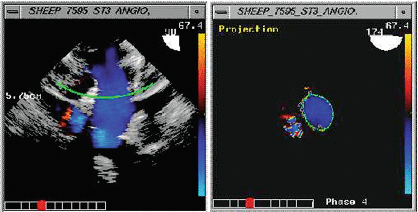

Fig. 2.13
(a) Rotational acquisition and (b) perpendicular Gaussian surface processing of three-dimensional stroke volume flow. This view is comparable to the TEE deep transgastric long axis view
Epicardial Echocardiography
In the late 1980s-early 1990s, epicardial echocardiography gained prominence as a method for real-time ultrasonic cardiac imaging in the perioperative setting [41, 92]. The epicardial approach required a standard transthoracic imaging probe encased in a sterile wrapping, and then placed directly upon the beating heart by the surgeon, who performed all probe manipulations. The surgeon or cardiologist could then monitor the images on the screen. While image quality was routinely excellent, the procedure was found to be logistically cumbersome for several reasons: (1) surgeons required a large number of cases (>200) to become proficient with the echo probe [43]; (2) since the surgeon needed to perform the scanning, the study interrupted the course of the operation, thereby prolonging surgery; (3) undesirable cardiac side effects (arrhythmias, hypotension) could occur with pressure of the probe upon the beating heart [93]. Thus as TEE technology evolved, it was not surprising that surgeons, anesthesiologists, and cardiologists alike expressed a preference for this method of intraoperative cardiac imaging, particularly as reports surfaced that TEE imaging quality and accuracy were comparable to that obtained by epicardial imaging [93, 94]. Though epicardial echocardiography still provided superior imaging of certain intracardiac structures such as the anterior ventricular septum and right ventricular outflow tract, TEE enabled a longer, more complete postoperative study, provided continuous imaging, and most importantly, did not interfere with the surgical field or the course of surgery. Thus TEE largely replaced epicardial echocardiography as the preferred modality for intraoperative echocardiographic imaging.
Nonetheless, epicardial echocardiography maintains a small but important role in the intraoperative/interventional setting. Guidelines published by the American Society of Echocardiography/Society of Cardiovascular Anesthesiologists specifically delineate training requirements, method of examination, and imaging planes for epicardial echocardiography [95]. These guidelines were subsequently endorsed by the Society of Thoracic Surgeons [96]. In adult patients, epicardial echocardiography provides important additional information in regard to the aortic valve and aorta [97–103] and pulmonary arteries [104]. For CHD evaluation, epicardial echocardiography can be helpful in those instances in which TEE cannot be performed due to small patient size or when there are congenital or acquired esophageal abnormalities. In pediatric patients, epicardial echocardiography can also be useful for the evaluation of extracardiac vascular abnormalities such as branch pulmonary artery and Glenn anastomosis obstruction [105]. It can also be helpful when performing hybrid interventional procedures [106–108]. Epicardial echocardiography has been reported with the use of a pediatric transthoracic 3D probe for the evaluation of mitral and aortic valves in adult patients [109, 110]. Comparable applications of epicardial 3D echocardiography for CHD have yet to be developed.
Intravascular Ultrasound and Intracardiac Echocardiography
Intravascular ultrasound (IVUS) and intracardiac echocardiography (ICE) are technologies that have undergone rapid changes and improvements since catheter-based ultrasound was first developed by Cieszynski in 1960 [111]. Bruce et al. broadly defined IVUS as the navigation and visualization of small blood vessels, such as coronary arteries, while the definition of ICE is the navigation and visualization of large blood-filled cavities or vessels in the cardiovascular system such as the right ventricle or pulmonary arteries [112]. Both IVUS and ICE use a catheter-mounted transducer to image the cardiac system.
Stay updated, free articles. Join our Telegram channel

Full access? Get Clinical Tree


