The physician implanting a cardiac rhythm device must have a thorough working knowledge of cardiac pacing, defibrillation, and resynchronization as well as a complete understanding of sterile technique and the specific surgical skills necessary for pulse generator implantation.1 For cardiac resynchronization therapy this also means thorough knowledge of coronary venous anatomy and techniques for cannulating and navigating the coronary venous system.
Also included in this chapter is a discussion of lead extraction as an implant-related procedure. Complications that may result from device implantation are discussed in Chapter 6: Implant-Related Complications.
Implantation Facility
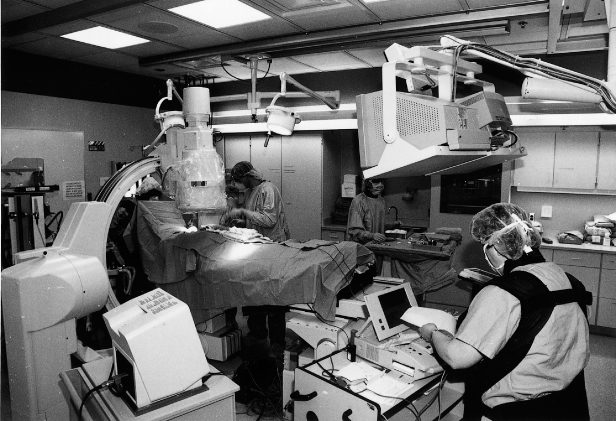
Pulse generators should be implanted in a surgical environment, whether a specially equipped operating room or a catheterization suite (Fig. 5.1). Requirements include excellent fluoroscopy, electrocardiographic monitoring, oxygen saturation monitoring (by finger plethysmography), and standby defibrillator and life-support equipment. Additional desirable features are facilities for simultaneous lateral and anteroposterior fluoroscopy projection, a fluoroscopy table capable of tilting, cineangiographic capability with freeze-frame, and intra-arterial pressure monitoring equipment.
Fig. 5.1 Pacemaker and implantable cardioverter-defibrillator implantation suite. Cardiac resynchronization therapy systems are implanted in a different area that is larger and has additional cine-angiographic capabilities.
Anesthesia
Local anesthesia is used for most adult patients unless contraindicated. Pediatric patients, uncooperative or confused patients undergoing device implantation, and patients with special circumstances may require general anesthesia. Lead extraction, discussed later in this chapter, is usually performed under general anesthesia.
Supplemental parenteral sedatives are used as needed for patient comfort.2 We commonly use intravenously administered midazolam and fentanyl, the dose depending on individual patient requirements, associated cardiopulmonary disease, other comorbidities, and age.
Conscious sedation may be administered by certified registered nurse anesthetists or registered nurses (RNs) trained specifically to perform this function. An expert consensus document is available that details the use of intravenous (conscious) sedation/analgesia by nonanesthesia personnel in patients undergoing device implantation and other electrophysiologic procedures.2
The Pulse Generator Pocket
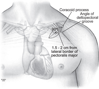
Forming the pulse generator pocket is an integral part of pulse generator implantation. The pocket is commonly developed in the prepectoralis fascia (Fig. 5.2). It should be large enough to allow for easy placement of the pulse generator and leads. It is important to avoid a pocket that is too tight, because it can result in erosion, or an oversized pocket, which can permit excessive movement and device migration (see Chapter 6, Implantation-Related Complications).
Fig. 5.2 Location of pacemaker pocket in upper left aspect of chest. Note that the incision is made parallel to and several centimeters below the lower clavicular margin.
(By permission of Mayo Foundation.)
The site of placement of the pulse generator is extremely important in providing long-term comfort and complete mobility for the adjacent shoulder. The pulse generator should be implanted in the subcutaneous tissue, deep to the fatty layer of the pectoral region. An inexperienced operator may not find the plane between the subcutaneous tissue and the pectoral fascia. Occasionally, the space developed may be subcuticular, with the subcutaneous fatty layer deep to the pulse generator. In that situation, the pulse generator presses on the undersurface of the skin, which may be continually painful. Characteristically, light touch of the overlying skin produces exquisite pain. An equally inexperienced evaluator of this circumstance may not understand the problem, which can be solved by repositioning the pulse generator into a deeper and subcutaneous site.
The pulse generator should be sufficiently inferior to the clavicle so that a full range of shoulder motion is not restricted by its impingement against the clavicle. The device should be sufficiently medial to keep it from approaching the anterior axillary fold. Otherwise, every anterior movement of the arm past the pulse generator will be uncomfortable.
Infiltration of local anesthetic in the deltopectoral groove (lateral incision) may also result in injury to the thoracoabdominal nerves and result in chronic pain. After dissection and development of the pocket it should be inspected for any bleeding and bleeding areas cauterized. A sponge soaked with saline or antibiotic solution may be kept within the pocket during placement of the leads in an effort to minimize oozing and blood in the field. However, removal of the sponge is mandatory before wound closure. We have discontinued this practice, given the potential for leaving a foreign object in the pocket (Fig. 5.3).
Fig. 5.3 Posteroanterior chest radiograph from a patient taken after a pacemaker implantation. The radiopaque material that is just superior and lateral to the pacemaker is a sponge that has been retained in the pocket.
As pulse generator size has decreased, this has become less of a selection parameter for most patients. The smallest available pulse generators may be of particular importance in pediatric patients, thin patients, and patients with cosmetic concerns. However, the downside of the smallest pulse generators is often a compromise in device longevity. If the prepectoral position is not suitable because the optimal pulse generator is too large or because cosmetic or other considerations predominate, other choices are possible. Although rarely necessary, the pulse generator can be placed deep to the pectoral muscle. When the implanting physician is experienced with this technique it can be accomplished with relative ease. It should not be performed by inexperienced implanters, because vascular and neural structures could be damaged if there is no familiarity with the anatomy encountered with this procedure.
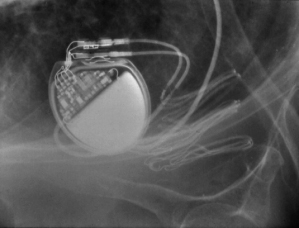
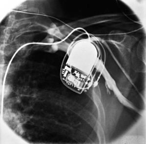
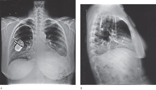
Retromammary pulse generator placement, a rarely used option, may be employed for cosmetic purposes or, in a thin person, for protection of the implant site by the fatty layer of the breast (Fig. 5.4). However, most contemporary pulse generators are small enough to be implanted prepectorally without causing any significant cosmetic concern. A potential disadvantage of a retromammary technique is that of potentially compromising breast imaging.
Fig. 5.4 Posteroanterior chest radiographs of a dual-chamber pacing system with the pulse generator located in a retromammary position.
Implantable cardioverter-defibrillators (ICDs) and cardiac resynchronization therapy (CRT) devices are larger than pacemakers and may cause more cosmetic concerns; placing either of these pulse generators in a retromammary position could potentially impair optimal mammography and therefore be of clinical concern. In fact, all devices should be implanted in such a way that the device obscures the minimum of breast tissue. It is also reasonable to be certain that a female patient has had recent mammography before ICD or CRT-D implantation.
Venous Approaches
Before 1979, transvenous pacing leads were almost always placed through a cephalic vein cutdown in the deltopectoral groove. If the cephalic vein was too small or friable, or had previously been used for implantation or if a second lead was required, the ipsilateral external or internal jugular vein was used. Rarely, subclavian or axillary vein cutdowns were performed. Deep dissection demanded precise surgical techniques – techniques in which cardiologists are not often skilled.
Each venous approach has its own particular advantages and disadvantages. The axillary, also referred to as the extrathoracic subclavian approach, subclavian puncture, and cephalic cutdown approaches, are most commonly used today. Placement through the external or internal jugular veins, in addition to more local dissection, requires the operator to tunnel the lead over or under the clavicle to the pulse generator and is largely of historical interest. Techniques for permanent lead placement via the iliac vein have also been described, and should be considered when there is limited venous access.
Axillary (Extrathoracic Subclavian) Approach
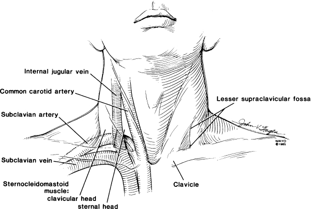
The introducer approach for axillary and subclavian venepuncture is frequently used, because this technique is fast, usually causes minimal trauma, and facilitates placement of multiple leads.3 The basic procedure, a modification of the Seldinger technique, requires detailed knowledge about the route of the axillary and subclavian vein and the relationship of the vein to the clavicle, first rib, arterial blood supply, and apex of the lung (Fig. 5.5). The ease, efficacy, and safety of the technique are directly related to adherence to specific guidelines and to the expertise of the physician performing the venepuncture.
Fig. 5.5 Relationships of clavicle, subclavian artery and vein, carotid artery, and internal jugular vein.
(From Holmes DR Jr. Permanent pacemaker implantation. In: Furman S, Hayes DL, Holmes DR Jr, eds. A Practice of Cardiac Pacing. Mount Kisco, NY: Futura Publishing Co., 1986:97–127, by permission of Mayo Foundation.)
Prepackaged kits containing a needle, guidewire, dilator, and peel-away sheath are available for venous puncture. The vein is entered through the incision with an 18-G needle (Fig. 5.6). (Placing the patient in the Trendelenburg position may facilitate entry, because the vein may be less distended in the recumbent patient with normal venous pressure. However, this is not an option with some tables used in the operating suite. Entry is even more of a problem if the patient has been fasting for several hours before the procedure and is volume-depleted.)
Fig. 5.6 The subclavian vein can be used for single- or dual-lead placement. The first step is to puncture the vein with an 18-G needle. Blood is aspirated to ensure proper positioning in the venous structure.
(By permission of Mayo Foundation.)
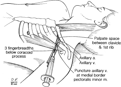
The axillary vein is a continuation of the brachial vein. The basilic and cephalic veins are tributaries of the axillary vein and the axillary artery courses alongside the axillary vein. The axillary vein terminates at the lateral margin of the first rib, at which point it becomes the subclavian vein, i.e., the axillary vein is extrathoracic. If venous access is accomplished in an extrathoracic position there is no risk of pneumothorax (Fig. 5.7).3 (Multiple techniques have been described for axillary puncture.4–6)
Fig. 5.7 Anatomic landmarks used for true axillary venepuncture.
(By permission of Mayo Foundation.)
The technique may be facilitated by inserting the needle in the lateral aspect of the incision. Under fluoroscopic guidance the needle is directed at the first rib, taking care not to cross the lateral margin of the first rib and thus avoiding entry into the intrathoracic space. The needle can be “walked” along the first rib. Venepuncture should be performed with a syringe with saline or 1% lidocaine attached to the needle. As the puncture is performed, a slight vacuum should be maintained on the syringe. The syringe should be constantly observed for the aspiration of air, blood, or other fluids. Once the vein is successfully punctured, the guidewire is advanced through the needle and into the right side of the heart under fluoroscopic control (Fig. 5.8). On occasion, this guidewire enters the jugular system and ascends. This error can usually be corrected by partial withdrawal of the wire, rotation, and readvancement under fluoroscopy. After removal of the needle, the introducer, dilator, and peel-away sheath are advanced over the guidewire into the central circulation (Fig. 5.9). Selection of the appropriately sized introducer is based on the size of the lead or leads to be used. After removal of the dilator and guide, the pacing lead or leads are advanced through the sheath into the right side of the heart. One should take care to avoid air embolism during this procedure. At a minimum, the patient should not talk during this portion of the procedure, and some implanters prefer to have the patient hold respiration until passage of the lead into the right side of the heart. The sheath is then peeled away (Fig. 5.10).
Fig. 5.8 The syringe is removed, the flexible guidewire is passed through the needle, and the proximal end of the wire is directed into the region of the right atrium.
(By permission of Mayo Foundation.)
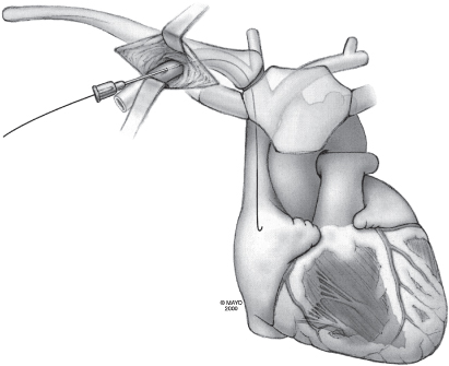
Fig. 5.9 With the guidewire in place, the needle is pulled back and off the guidewire. The dilator and peel-away sheath are then placed over the guidewire and passed into the subclavian vein. As the dilator and sheath are being passed into the vein, a hemostat is placed on the guidewire to prevent loss of the wire into the venous circulation.
(By permission of Mayo Foundation.)
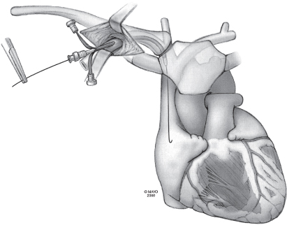
Fig. 5.10 The guidewire and dilator are removed from the sheath, and the pacing lead is quickly passed through the sheath into the right atrium. Arrows indicate pulling of the peel-away introducer from the lead.
(By permission of Mayo Foundation.)
If the vein is not successfully located by probing with walking the needle along the first rib, a peripheral contrast injection will allow visualization of the axillary vein and redirection of the needle to the point on the first rib where the vein is identified. Some implanters prefer to perform contrast venography before the initial puncture attempt.
Contrast venography requires no additional preparation with the exception of determining that the patient does not have a contrast allergy and placing an intravenous line (preferably 20 G or larger) in the arm on the side of the pulse generator implantation.7,8 The intravenous line should be checked for patency before injection of contrast material. The contrast injection can be carried out by anyone in the room with access to the peripheral, ipsilateral intravenous line. Approximately 10–20 ml of preferably nonionic, iodinated contrast medium is injected through the intravenous line in the forearm. A saline bolus may be used to flush the contrast agent into the venous system if necessary. It may also be helpful to massage the arm to assist in venous return and venous visualization. This can be done either under the sterile drapes by an assistant or over the sterile drapes by the implanter. The subclavicular area is monitored with fluoroscopy for the appearance of contrast, which usually takes 5–20 s (Fig. 5.11). Repeat injections are given as needed, although the total contrast burden should be monitored and kept to the minimum possible, and the implanter should be aware of the patient’s renal function. If the contrast venogram demonstrates a nonpatent vein, the implanting physician may need to choose a different venous route. This may be especially useful when a new lead needs to be placed due to a failed lead or when upgrading a system (Fig. 5.12).
Fig. 5.11 Contrast venogram obtained during venepuncture. With contrast in the vein, the venepuncture needle (arrow) can be positioned directly into the vein under fluoroscopic guidance.
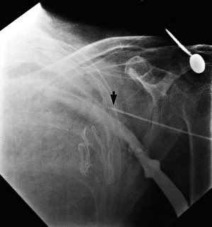
Fig. 5.12 Contrast venogram shows an occluded right subclavian vein in a patient with a long-term pacing lead in the subclavian vein. The venogram was obtained before attempted placement of an atrial lead and a dual-chamber pacemaker. The image was obtained approximately 15–20 s after contrast injection.
(From Holmes DR Jr. Permanent pacemaker implantation. In: Furman S, Hayes DL, Holmes DR Jr, eds. A Practice of Cardiac Pacing. Mount Kisco, NY: Futura Publishing Co., 1986: 97–127, by permission of Mayo Foundation.)
As noted, some implanters prefer to use contrast venography routinely. Alternatively, in patients with normal costoclavicular relationships, no prior permanent pacing leads, and no venous thrombosis, a “blind” venepuncture can be first attempted as previously described. In patients who may have unusual venous anatomy, it may be desirable to use contrast venography before the initial attempt to ensure venous patency and location. Such patients might include those with kyphoscoliosis, prior clavicular fracture, prior surgery in the vicinity of the puncture site, or previous lead implantation. For difficult cases, ultrasound can also be used to identify the position of the vein by placing the probe in a sterile sleeve.
Subclavian Approach
Although subclavian puncture was the preferred venous route at one time, many implanters have converted to an axillary approach to minimize the risk of pneumothorax. However, implanting physicians should be familiar and comfortable with the subclavian approach. Historically, it was taught that the subclavian vein was entered at the junction of the middle and inner thirds of the clavicle or even with a very medial approach, which was referred to as the “safe introducer technique.” A very medial approach predisposes the lead or leads to crush injury between the clavicle and the first rib.9 As with the axillary technique, some implanters prefer a contrast-guided technique. The anteroposterior location of the subclavian vein is not appreciated with anteroposterior fluoroscopy. Needle passes may occasionally be too anterior or posterior, despite appearing to be within the column of contrast. Varying the fluoroscopic view may aid exact visualization of the vein.
Potential complications of subclavian vein puncture include pneumothorax, hemopneumothorax, lung laceration, inadvertent arterial puncture, air embolism, arteriovenous fistula, thoracic duct injury, and brachial plexus injury. Pneumothorax is the most common complication, but, as noted above, use of contrast venography minimizes this risk. Contrast venography also lessens the risk of inadvertent subclavian artery puncture. Meticulous attention to technique is required to minimize any of these risks.
Cephalic Approach
Some implanters prefer the cephalic cutdown approach, which avoids the risks of a pneumothorax.10 The cephalic vein lies within the deltopectoral groove. The deltopectoral groove is a constant anatomic site between the deltoid and pectoralis major muscles. The cephalic vein always accommodates a single lead and often accommodates two leads. The operative skills required for the cephalic approach are modest and can be readily taught to anyone sufficiently skilled to perform subclavian puncture or other invasive cardiovascular procedures. Cannulation of the cephalic vein is free of significant complications. If damaged, the vein can be ligated, with prompt cessation of bleeding. In addition, the normal venous pressure and the venous valves prevent aspiration of air into the central circulation.
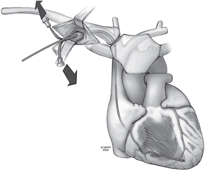
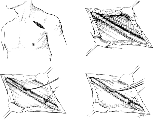
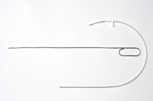
If the cephalic vein is too small to accommodate even a single lead, a guidewire technique may be useful. For this technique, the cephalic vein is opened in the usual manner, but instead of attempting to pass the lead, the implanter places a guidewire through the opening into the superior vena cava (SVC) or right atrium. The introducer is then placed over the guidewire, as in a conventional subclavian approach, and a lead or leads are introduced (Fig. 5.13).
Fig. 5.13 A partial cephalic cutdown and introducer technique involves exposure of the cephalic vein in the deltopectoral groove (upper left and upper right). If the vein is too small to accept a lead, a guidewire is placed (lower left) and an introducer over it (lower right).
(From Holmes DR, Hayes DL, Furman S. Permanent pacemaker implantation. In: Furman S, Hayes DL, Holmes DR Jr, eds. A Practice of Cardiac Pacing, 2nd edn. Mount Kisco, NY: Futura Publishing Co., 1989: 239–287, by permission of Mayo Foundation.)
Jugular Approach
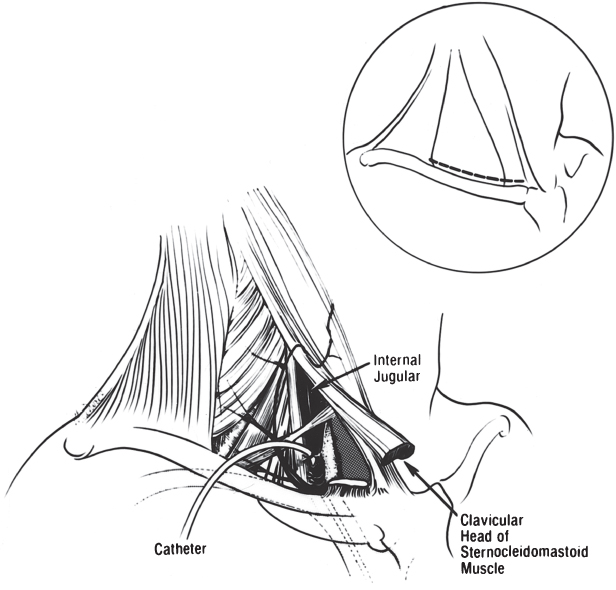
This approach is largely of historic interest and should be attempted only by someone with a thorough knowledge of the anatomy and required techniques. In the unusual situation where the external or internal jugular vein is selected, two incisions are required. An incision is made immediately above the clavicle, over the area between the posterior border of the sternocleidomastoid muscle and the anterior border of the trapezius muscle.1 External jugular access to the heart is usually easier by the right external jugular vein than by the left, because the vessel is often less tortuous. If no satisfactory external jugular vessel is found, the incision is extended to a point anterior to the clavicular head of the sternocleidomastoid muscle. The carotid sheath is exposed after the superficial fascia is opened behind the posterior border of the sternocleidomastoid muscle. The muscle is then elevated to visualize the carotid sheath optimally. On occasion, the clavicular head of the sternocleidomastoid muscle must be divided to expose the carotid sheath (Fig. 5.14). The carotid sheath is then opened; the internal jugular vein is identified and isolated with nonabsorbable ligatures. After venotomy, the lead or leads can be introduced. Use of either the external or the internal jugular vein requires that the lead be tunneled down to the pulse generator site, either superficial or deep to the clavicle. In addition, the internal jugular procedure requires more extensive dissection, with the possibility of damage to the subclavian artery and vein and the recurrent laryngeal nerve.
Fig. 5.14 Approach to the internal jugular vein. An incision (inset) is made immediately above the clavicle. The carotid sheath is exposed and then opened (see text for details).
(From Brodman R, Furman S. Pacemaker implantation through the internal jugular vein. Ann Thorac Surg 1980; 29:63–5, by permission of The Society of Thoracic Surgeons.)
An alternative method of placing a pacemaker lead via the internal jugular vein is with percutaneous access to the jugular vein and subsequent tunneling of the lead to an infraclavicular pocket. In this approach, cutdown of the jugular vein is not performed. Rather, a standard Seldinger technique with percutaneous access to the supraclavicular portion of the internal jugular vein is performed. Once access has been obtained, a peel-away sheath and, through this, the pacing lead is placed as described below. A small incision at the site of jugular venepuncture is created and the leads secured in the region of this incision. A second infraclavicular incision is made and the pacemaker pocket fashioned as usual. The pacing lead is now tunneled (usually over the clavicle) and secured with a sleeve onto the pectoralis muscle as well. Some operators may only secure the lead to the pectoralis muscle with no suturing of the lead above the clavicle. The lead is then interfaced with a generator in the usual fashion.
Iliac Vein Approach
Although rarely used at our institution, the iliac vein approach is worth knowing in the event that the more commonly used venous routes are not accessible (Fig. 5.15). Transiliac implantation has been described in patients with obstructed SVC, congenital cardiac anomalies, or infected prepectoral pacemakers requiring extensive débridement.11,12
Fig. 5.15 Schematic approach to the iliac vein and pulse generator positioning.
(By permission of Mayo Foundation.)
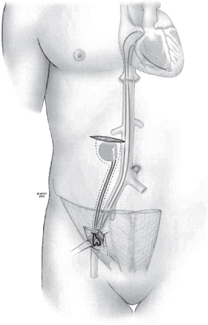
The recommended procedure is to puncture the iliac vein with a standard puncture technique after making a small incision just above the inguinal ligament and to carry the dissection down to the fascia above the vein. After the puncture is made and lead or leads placed, a purse-string suture is placed to provide hemostasis. A pocket, superficial to the rectus sheath, is created lateral to the umbilicus.13,14
Ventricular Lead Placement
Successful placement of a reliable right ventricular (RV) pacing system requires knowledge of, and experience with, the specific lead used, as well as knowledge of right heart anatomy and catheterization techniques. Great care must be taken during implantation to avoid damage to the lead. The lead stylet, in particular, should not be forced, because forcing may result in perforation of the stylet through the conductor coil and into the insulation. Keeping the stylet clean, free of blood, and moistened with saline helps avoid trauma to the lead during multiple stylet changes. Several placement techniques are used; all must result in a stable RV catheter position with adequate pacing and sensing thresholds. RV pacing leads have most commonly been positioned in the RV apex. However, a great deal of controversy exists over whether other positions, such as the septum or outflow tract, may be hemodynamically superior. A nonapical site may also need to be considered because of local myocardial problems, such as previous inferoapical infarction, or possibly to decrease the risk of perforation. In thin patients, a distal apical position may predispose towards costal muscle stimulation.
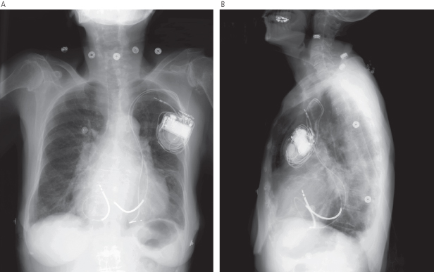
When any lead is initially advanced into the central circulation, it should first be seen to pass to the right of the vertebral column through the SVC. If the lead is introduced from the left side and passes to the left of the vertebral column, it is probably within a persistent left SVC, assuming venous (as opposed to arterial) access is confirmed (Fig. 5.16). If this occurs, there are two options. One is to continue to advance the lead or leads through the coronary sinus (CS) towards the right atrium. Although this approach has been used many times, lead placement can be difficult. This results because the lead will enter the right atrium from the CS at an angle that makes positioning in traditional atrial and ventricular sites challenging. The alternative is to abandon the procedure and then perform contrast venography from a peripheral intravenous line in the right arm to determine whether a right-sided SVC also exists. If it does, the implant site can be moved to the right and leads placed in a traditional manner. One should be more alert to the possibility of a persistent left SVC in a patient with associated congenital anomalies.
Fig. 5.16 Posteroanterior (A) and lateral (B) chest radiographs show leads placed through a persistent left superior vena cava.
The lead can be initially passed through the introducer with a straight or a curved stylet in place. A curved stylet is helpful in introducing the lead across the tricuspid valve and into the pulmonary outflow tract. (A curved stylet is created by wetting the stylet and the gloved index finger and thumb and pulling the stylet through the apposed fingers while rotating the fingers to impart a curve to the wire. A curve can also be formed by pulling the distal end of the stylet between the index finger and needle-driver or other instrument.) Initially placing the lead in the outflow tract ensures that the lead is indeed in the RV and not in the CS or in an extracardiac vessel, such as the hepatic vein. The lead may cause premature ventricular contractions as it passes through the RV, but these are usually inconsequential. Once the lead tip is in the outflow tract, the curved guidewire should be replaced with a straight stylet. The straight stylet is not passed completely into the lead initially. The lead should be slowly withdrawn from the outflow tract, allowing the lead tip to fall toward the RV apex. The stylet should be simultaneously advanced as the lead is slowly withdrawn, allowing the straightened lead to fall toward the apex. Once the lead falls from the outflow tract and is directed towards the apex, the lead, with stylet in place, should be advanced towards the apex. This maneuver may be assisted by asking the patient to breathe deeply, causing the RV apex to descend with the diaphragm, at which point the lead can be advanced.
Another technique involves using the curved stylet to advance the lead into the RV. Instead of continuing to advance the lead all the way to the outflow tract, the stylet is withdrawn in the inlet portion of the RV itself. By withdrawing the curved stylet, the lead tends to “straighten” and can be advanced towards the apex. If advance of the lead becomes hindered by an intracavitary structure such as the moderator band, then the curved stylet can be readvanced until the tip of the lead points upward and now can be advanced over the moderator band. By repeating the maneuver (withdrawing the stylet to straighten the leads and advancing when an obstruction is encountered), the lead tip can be “marched” towards the septal portion of the RV apex.
It is sometimes possible to position the lead without a curved stylet. Once the lead is in the right atrium, the straight stylet should be withdrawn about 5 cm and the lead moved inferiorly. It will often catch in the right atrium and be deflected toward the tricuspid valve (Fig. 5.17). If the lead passes the tricuspid valve, it will be in the inflow tract of the RV.
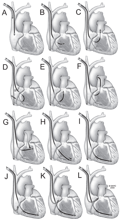
Fig. 5.17 Intracardiac manipulation is basic to successful pacemaker implantation. Implantation of a dual-chamber pacemaker involves placement of an atrial and a ventricular lead. (A) Both leads may be introduced via the subclavian, cephalic, or external jugular vein. Initially, both are in the superior vena cava or the right atrial appendage. (B) Because ventricular stimulation is usually more important than atrial stimulation, the ventricular lead is positioned first. The atrial lead can be introduced immediately after or simultaneously with the ventricular lead or introduced after the ventricular lead is positioned. If the atrial lead is introduced before ventricular lead positioning, the atrial lead can be left in the upper inferior vena cava or low right atrium until time to position the lead. (C) Once the ventricular lead is past the tricuspid valve and in the midright ventricle, it should be advanced into the pulmonary artery so that it is clear that it has not entered the coronary sinus (panel F). (D) If the lead tip will not pass the tricuspid valve, entry by deflection from the lateral atrial wall may be successful. (E) Advancing the bowed lead in the right ventricle and then the guidewire within the bow can flip the lead tip into the right ventricular outflow tract. Note that during this entire maneuver, the atrial lead is “parked” in the inferior vena cava. (F) As above, the lead is passed into the pulmonary artery. (G) Once there, the lead is slowly withdrawn so that it falls toward the right ventricular apex. (H) Once at the diaphragmatic surface of the ventricle, the lead is advanced into the apex. A deep breath angulates the apex downward and allows easier access. (I) When the ventricular lead has been positioned properly, the guidewire is allowed to remain withdrawn about 2 cm from the tip to hold it in position while the atrial lead is being manipulated. (J) Because the two leads often adhere lightly to each other, when one lead is manipulated, the other should be held so that it is not inadvertently displaced. The atrial lead should be pulled into the low right atrium and the guidewire withdrawn about 7 cm; the J will form. (K) The atrial lead should then be pulled upward slowly. Entry into the base of the atrial appendage is recognized by straightening of the J with gentle traction on the lead. (L) Additional traction is stopped, and the lead is advanced into the tip of the atrial appendage.
(By permission of Mayo Foundation.)
Another situation where a straight stylet alone is useful in getting a lead to the RV is with right-sided implantations and a torturous subclavian–SVC system. Here, because of the near right-angle turn from the right subclavian vein into the SVC, a curved stylet will tend to point the lead in the atrium and make it difficult to cross the tricuspid valve. In this situation, a straight stylet can be used to advance into the right atrium. Now, by pulling back the straight stylet, the lead is advanced until it curves in the right atrium itself. Now, the lead is rotated so that the heel of the curved lead begins to prolapse across the tricuspid valve. In a simultaneous maneuver, the straight stylet is then advanced while pulling back the lead. As the heel of the prolapsed lead now begins to be extended, the straight stylet reaches near the tip of the lead and the lead falls into the inflow portion of the RV, often close to the RV apex.
Alternatively, with the straight stylet withdrawn approximately 5 cm, the lead tip can be projected against the lateral atrial wall and the curved portion of the lead backed into the tricuspid valve.
These maneuvers are readily visible fluoroscopically and, if seen, ensure that the lead has traversed the RV. The lead occasionally enters the CS from the right atrium. A lead within the CS may appear to be within the RV, but the passage is not superiorly but rather more laterally toward the left cardiac border. Should the lead begin to curl about the left cardiac border, it is likely to be in the CS. In addition, no ventricular ectopy occurs if the lead is in the CS. Attempts at entering the pulmonary artery will be unsuccessful, but the most important clue is in the lateral fluoroscopic view. The outflow tract of the RV is an anterior structure, and a lead in it is seen in the retrosternal position. The CS is on the posterior wall of the heart, and a lead within it is visualized on the posterior cardiac border.
When the ventricular lead is positioned in the RV apex, radiographically, the end of the ventricular lead appears on the posteroanterior projection to be between the left border of the vertebral column and the cardiac apex. The position of the heart, vertical or more horizontal, largely determines the position of the lead in relation to the cardiac apex and varies among patients. The lateral view is necessary to distinguish between apical positions in which the lead tip is anterior and caudally directed, is posteriorly directed in the RV, and is on the posterior surface of the heart, i.e., within the CS. Fluoroscopically, in the right anterior oblique (RAO) view, the fat pad highlights the atrioventricular (AV) valve plane, and if the lead is in the CS it tracks along this plane, unless it falls into a ventricular cardiac vein. In contrast, a lead in the RV will have a course orthogonal to this radiographic view and will be seen going towards the apex. In the left anterior oblique (LAO) view, a lead in the RV is coming towards the image intensifier, whereas one in the CS has a distinguishing leftward trajectory. On the posteroanterior radiographic view, the ventricular lead should have a gentle curve along the lateral wall of the right atrium and cross the tricuspid valve to the ventricular apex (Fig. 5.18). Additionally, the LAO projection will help distinguish a septal from free wall (risk of perforation) location of the lead tip.
Fig. 5.18 Posteroanterior (A) and lateral (B) chest radiographs demonstrating gentle curve of the ventricular lead as it passes across the tricuspid lead.
If an atrial lead is not to be implanted, the guidewire can be removed from the ventricular lead and the lead can be checked for stability by deep breathing or coughing and by assessment of pacing and sensing thresholds. In addition, diaphragmatic stimulation should be assessed. Our technique is to pace at 10 V, the maximum voltage available on the pacing system analyzer used. During 10-V pacing, the left hemidiaphragm is assessed fluoroscopically for detection of pacing-induced excursions of the diaphragm. If an atrial lead is being tested, the right hemidiaphragm is assessed fluoroscopically. Alternatively, a hand can be placed over the appropriate hemidiaphragm to feel for diaphragmatic stimulation. If diaphragmatic stimulation occurs, the lead should be repositioned. Intercostal stimulation should also be looked for during high-output pacing.
As previously noted, it may be desirable to position the lead somewhere other than in the RV apex. The hemodynamic superiority of one position over the other has not yet been firmly established. However, so long as pacing and sensing thresholds are acceptable and the lead is secure, it can be positioned anywhere within the right ventricle.
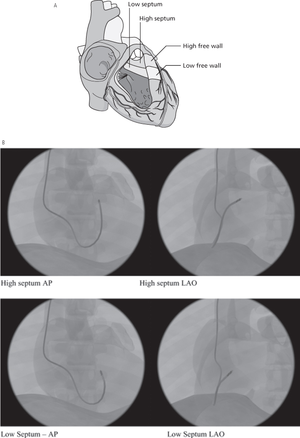
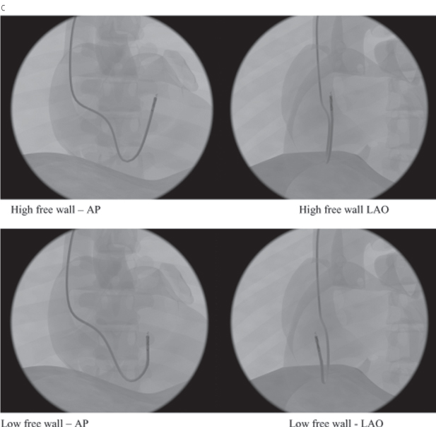
Because of the difficulty in comparing different ventricular pacing sites, nomenclature is necessary to allow uniform description of proposed alternative RV pacing sites (other than apical pacing).15 One approach would be to define the sites as high septal, low septal, high free wall, and low free wall16 (Fig. 5.19A). Radiographic representations of high and low septal (Fig. 5.19B), and high and low free wall (Fig. 5.19C) are also shown.
Fig. 5.19 (A) Schematic drawing of low and high septal and low and high free wall positions for right ventricular outflow tract lead positioning. (B) High and low septal lead positions in anteroposterior (AP) and left anterior oblique (LAO) projections. (C) High and low free wall positions in AP and LAO projections.
(From Vlay SC. Right ventricular outflow tract pacing: practical and beneficial: a 9-year experience of 460 consecutive implants. Pacing Clin Electrophysiol 2006; 29:1055–62, by permission of Blackwell Publishing.)
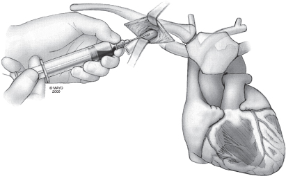
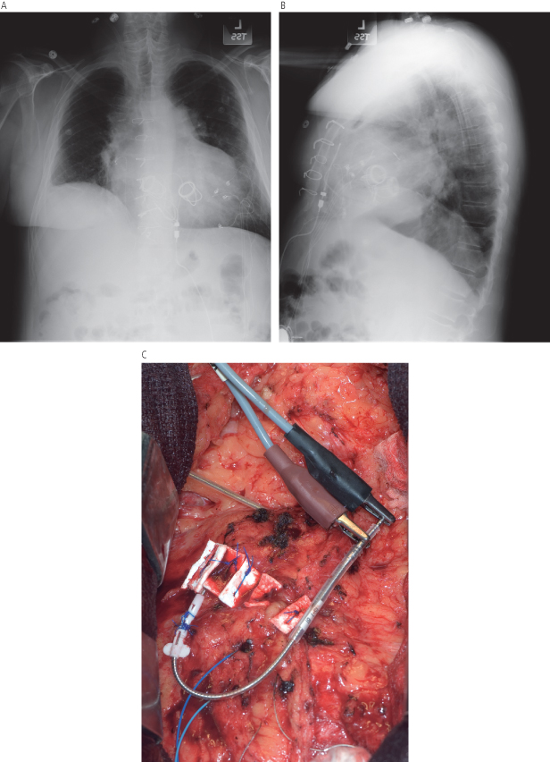
Special circumstances may lead to innovative lead positioning. One example would be the patient with a congenital anomaly or prosthetic tricuspid valve that prevents transvenous access to the nonsystemic ventricle. Although CS lead positioning may permit transvenous pacing in a patient in whom the right ventricle is not accessible, in some patients, especially those with a congenital anomaly, the CS may not be accessible. An approach that we have occasionally used for such a patient, in collaboration with our cardiovascular surgeons, is transmyocardial lead placement (Fig. 5.20).
Fig. 5.20 Posteroanterior (A) and lateral (B) chest radiograph from a patient with transposition of the great vessels and prosthetic valves in both the tricuspid and mitral positions and complete atrioventricular block with pacemaker dependency. An active fixation steroid-eluting transvenous lead was placed via a transmyocardial approach. (C) Photograph obtained in the operating room at the time the lead was placed.
The ventricular lead of an ICD system, whether single-chamber or dual-chamber, is placed in exactly the same manner as described above. However, alterations in technique may be required if defibrillation thresholds are unacceptable. Historically, we would routinely place the lead as apically as possible in most patients. If the patient requires bradycardia support there may be adverse hemodynamic consequences to RV apical pacing. The RV lead can be placed in any RV position where the lead is stable and pacing, sensing, and defibrillation thresholds meet expectations. Often, use of a low apical septal location results in acceptable function. If the defibrillation thresholds are unacceptable, the lead should be repositioned to an alternative RV site where thresholds are again acceptable. Acceptable thresholds can be obtained with a single RV lead in >95% of patients.17
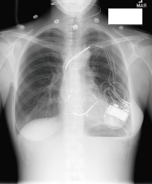
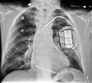
If adequate defibrillation thresholds cannot be achieved despite repositioning of the RV lead, retesting with reversal of polarity is often assessed, although its benefit has been questioned, particularly if the RV coil is the anode (positive electrode).18 If a single-coil lead is used, a SVC coil can be added either as a separate lead or more commonly by exchanging the single-coil lead for a dual-coil lead (Fig. 5.21). This results in acceptable defibrillation thresholds for most patients. In our pratice, we preferentially use dual-coil leads, and infrequently use single-coil leads. If defibrillation safety margins remain unacceptable, remaining options include using a pulse generator with programmable waveforms (St. Jude Medical), or the addition of another venous defibrillation electrode (such as the CS), or use of a subcutaneous array.19
Fig. 5.21 Posteroanterior chest radiograph of an implantable cardioverter-defibrillator system that has a superior vena cava coil in addition to the right ventricular lead.
A subcutaneous lead is infrequently needed to achieve an adequate defibrillation threshold. Two types of subcutaneous leads are currently available. A subcutaneous array consists of three electrically common multifilar coils that form one electrode (Fig. 5.22). The coils come together in an insulated cable that is connected to a terminal pin that can be connected to the connector block. The “array” provides a greater surface area over the lateral chest to facilitate defibrillation (Fig. 5.23). Our approach for the placement of the “array” is to make an incision near the midaxillary line at the level of the nipple. Dissection is carried to the level of the muscle. With a trochar that is supplied with the array, three tunnels are formed, one at a time, with a peel-away introducer over the trochar. The trochar is removed, and one of the three coils is placed within the sheath, which is carefully peeled away. Once all three are placed, each coil is secured to the underlying tissue with the sleeve provided, and the “yoke,” or point where the three coils join, is secured to the underlying tissue as well. The insulated cable is then passed into the inferior portion of the previously formed prepectoral pocket and connected to the ICD.
Fig. 5.22 The subcutaneous array is supplied with a three-coil lead that connects to a single body for connection to the cardioverter-defibrillator (left), peel-away sheaths for each of the three coils (center), and a trochar for lead placement (right).
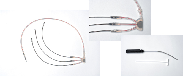
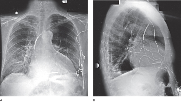
Fig. 5.23 Posteroanterior (A) and lateral (B) chest radiographs of an implantable cardioverter-defibrillator system that incorporates a subcutaneous array. Adequate defibrillation thresholds could not be achieved without the array.
A subcutaneous lead is also available as a single element or finger.20 This variety, also placed with a trochar as previously described, can sometimes be placed via the inferior portion of the pocket, obviating the need for a separate incision (Fig. 5.24).
Implantation of venous defibrillation electrodes has been described in the coronary sinus, inferior vena cava, azygous vein, and epicardial space.21,22
Coronary Sinus Lead Placement
CS lead placement for left ventricular stimulation is commonly used in patients who meet criteria for CRT. The hemodynamic implications of biventricular stimulation or cardiac resynchronization are discussed in detail in Chapter 2: Hemodynamics of Cardiac Pacing.
Familiarity with placing left ventricular leads as part of biventricular device implantation is important, as up to 50% of new ICD implants are CRT systems at some US centers. It is imperative that the implanting physician has a thorough knowledge of coronary venous anatomy (Figs 5.25–5.27).
Fig. 5.25 Coronary sinus (CS) and ventricular vein anatomy ideally are visualized in two orthogonal fl uoroscopic views. In the right anterior oblique (RAO) projection, the CS is viewed end-on. The ostium of the CS is just superior to the usually visualized translucency of the posterior fat pad. The body of the CS and great cardiac vein proceed end-on, separating the ventricles and atria. In this projection, the ventricular veins then proceed towards the sternum (towards the right, as depicted in the left image). In this view, right-sided and left-sided positions are not readily distinguished. In the left anterior oblique (LAO) projection, the ostium of CS is in the plane of the interatrial septum. The vein proceeds posteriorly from right to left, wrapping around the lateral wall of the heart. In this view, atrial and ventricular veins cannot be distinguished. The LAO projection is ideal for distinguishing lateral and septal locations of veins and contained leads. Thus, the LAO view defines left vs. right position, and the RAO view defines atrial vs. ventricular position.
(From Chapter 4, Biventricular device implantation. In: Hayes DL, Wang PJ, Sackner-Bernstein J, Asirvatham SJ, eds.Resynchroniszation and Defibrillation for Heart Failure: A Practical Approach. Oxford, UK: Blackwell Futura, 2004.)
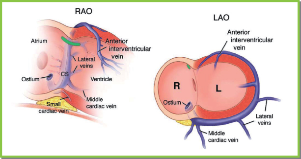
Fig. 5.26 The lateral left ventricle (LV) is drained by branches of the posterolateral vein (PLV) in most patients. It should be noted that lateral branches of the anterior intraventricular vein and lateral branches of the middle cardiac vein also drain this region. CS, coronary sinus; LA, left atrium.
(From Chapter 4, Biventricular device implantation. In: Hayes DL, Wang PJ, Sackner-Bernstein J, Asirvatham SJ, eds. Resynchronisation and Defibrillation for Heart Failure: A Practical Approach. Oxford, UK: Blackwell Futura, 2004.)
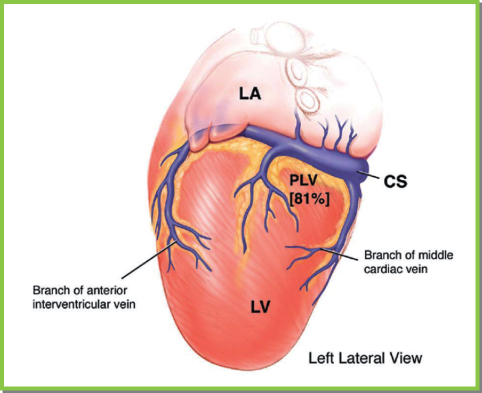
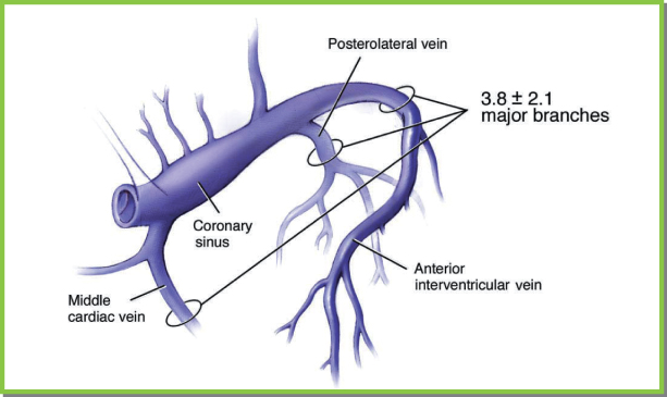
Fig. 5.27 Ventricular venous anatomy. Three to four ventricular veins are seen fairly consistently. The middle cardiac vein can be either close to or widely separated from the posterolateral vein. When the posterolateral vein is close to the middle cardiac vein, lateral branches of the anterior intraventricular vein or a separate lateral vein drain the left ventricular free wall.
(From Chapter 4, Biventricular device implantation. In: Hayes DL, Wang PJ, Sackner-Bernstein J, Asirvatham SJ [eds] Resynchronisation and Defibrillation for Heart Failure: A Practical Approach. Oxford, UK: Blackwell Futura, 2004.)
Left ventricular leads may be deployed by either a right-sided or left-sided implant. We generally place CS leads from the left side. If placing a CS lead from the right, there are specific differences in sheath and lead manipulation, discussed below.
We avoid placing multiple leads through a single venepuncture site because of the propensity for lead dislodgment while manipulating the nonleft ventricular leads, for an increase in backbleeding, and for difficulty with sheath or left ventricular lead manipulation.
The left ventricular lead may be placed before or after the right ventricular and right atrial leads have been placed. The advantages of placing the left ventricular lead first include greater ease in maneuvering the guiding sheath and lead, elimination of the risk of partial occlusion of the orifice of the CS with the RV lead, and prevention of inadvertent RV lead manipulation in the CS, resulting in spasm or dissection. The major advantages of placing the RV lead first include a fixed reference to the apex (thus delineating the interventricular septum) and tricuspid annulus and ventricular pacing support if the patient has extensive conduction system disease. We prefer to place the left ventricular lead first. In difficult cases, particularly with asymmetric dilatation of the left ventricle or clockwise rotation of the heart (or both), the RV lead is placed at the apex first to provide optimal orientation.
The RAO projection is used to define the tricuspid valve annulus, and the LAO projection is used to define the interventricular septum and apex. In patients with dilated cardiac chambers, the “usual” amount of RAO and LAO to achieve this orientation may be insufficient. The characteristic change in the contour of the RV lead at the tricuspid annulus and its placement at the apex can help to line up these views in a given patient.
Coronary Sinus Cannulation
Once venous access has been established, the CS must be cannulated with a guiding sheath. The ventricular lead is deployed through the sheath, after which the sheath is removed. Attention to detail and experience in troubleshooting problems that arise with cannulating the CS will decrease procedure time and minimize CS-related complications.23
The Guiding Sheath
Several varieties of guiding sheaths are available, but there are major differences in shape and method of sheath removal. Straight sheaths with no preformed curves typically require a deflectable catheter for initial cannulation of the CS. Preformed curves are available in several varieties; no one curve is ideally suited for all hearts. Generally, gentle curves are preferred to give flexibility if subselection of a coronary vein is required or multiple catheter exchanges are needed to cannulate the CS. The ideal curve allows the body of the catheter to rest against the free wall of the right atrium and yet engage the CS ostium. This type of stability allows torque application to probe the ostial septum anterior to the Eustachian ridge in both the anteroposterior and superoinferior directions.
Use of Angiographic Wires vs. Deflectable Electrophysiologic Catheters to Engage the Coronary Sinus
Angiographic wires that are soft-tipped and torquable are well suited for use with preshaped guiding sheaths.24 To engage the CS, the wire is advanced preferably as far as the natural curve of the CS, great cardiac vein, anterior vein, and interventricular vein will allow. The guiding sheath is then advanced along the wire while the wire is pulled back. The sheath should not be advanced when the wire has not freely advanced into the axis of the coronary veins. This is to avoid CS dissection. If the wire has not advanced sufficiently to allow it to be pulled back a substantial amount while the sheath is being advanced, then repeatedly pulling back the wire and readvancing the sheath in small increments will allow the CS to be safely engaged with the guiding sheath (Fig. 5.28).
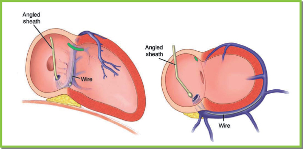
Fig. 5.28 Cannulating the coronary sinus with a guidewire. If a curved or angled sheath is employed, guidewire can be used to engage the coronary sinus and its tributaries. With the sheath rotated counterclockwise so that it points septally in the left anterior oblique projection, the wire is advanced gently, and it is seen to take the typical course of the vein in both the right and left anterior oblique projections.
(From Chapter 4, Biventricular device implantation. In: Hayes DL, Wang PJ, Sackner-Bernstein J, Asirvatham SJ, eds. Resynchronisation and Defibrillation for Heart Failure: A Practical Approach. Oxford, UK: Blackwell Futura, 2004.)
Deflectable electrophysiologic catheters can be used with either straight or preformed curved guiding sheaths. We often use deflectable catheters capable of recording electrograms and whose deflection mechanism allows bidirectional changes. After the CS has been cannulated, pulling back on the catheter slightly while advancing the sheath will allow the sheath to be deployed into the CS (Figs 5.29–5.31).
Fig. 5.29 Either straight or curved sheaths can be used with a defl ectable catheter to engage the coronary sinus. The catheter is deflected just above the posterior fat pad in an end-on manner in the right anterior oblique projection and points septally and leftward in the left anterior oblique projection. Care should be taken that once the catheter has engaged the coronary sinus, the sheath should be advanced to the ostium of the coronary sinus with gentle pulling back of the catheter (see text).
(From Chapter 4, Biventricular device implantation. In: Hayes DL, Wang PJ, Sackner-Bernstein J, Asirvatham SJ, eds. Resynchronisation and Defibrillation for Heart Failure: A Practical Approach. Oxford, UK: Blackwell Futura, 2004.)
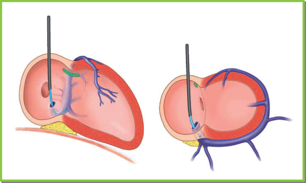
Fig. 5.30 Advancing the guiding sheath into the coronary sinus. After the sheath has been placed in the ostium of the coronary sinus, the defl ectable catheter is advanced to the region of the desired vein. While pulling back on the catheter, advance the sheath and then advance the catheter again. Repeat this maneuver until the desired location in the venous system has been obtained. LAO, left anterior oblique; RAO, right anterior oblique.
(From Chapter 4, Biventricular device implantation. In: Hayes DL, Wang PJ, Sackner-Bernstein J, Asirvatham SJ, eds. Resynchronisation and Defibrillation for Heart Failure: A Practical Approach. Oxford, UK: Blackwell Futura, 2004.)
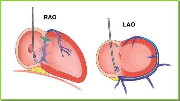
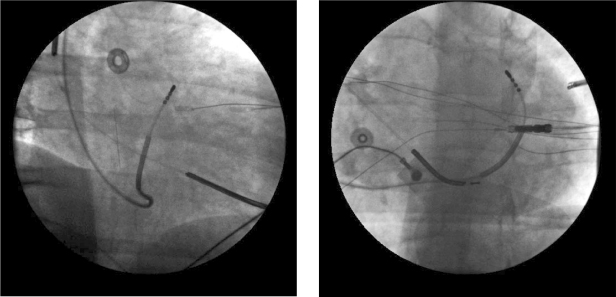
Fig. 5.31 Right anterior oblique (left panel) and left anterior oblique (right panel) projections showing cannulation of the great cardiac vein using a defl ectable catheter.
(From Chapter 4, Biventricular device implantation. In: Hayes DL, Wang PJ, Sackner-Bernstein J, Asirvatham SJ [eds] Resynchronisation and Defibrillation for Heart Failure: A Practical Approach. Oxford, UK: Blackwell Futura, 2004.)
A third option entails using preformed curved sheaths designed to facilitate CS access, in conjunction with gentle puffs of contrast to confirm cannulation. The sheath may have an obdurator within it to provide mechanical support, or a smaller sheath with a 50–90° bend at the distal end. Most commonly, such a sheath or sheath-within-a-sheath system is positioned in the RV at the septum. Gentle counterclockwise torque and slight retraction of the guiding sheath results in the distal tip approaching the ostium of the CS. Gentle puffs of contrast outline characteristic endocardial contours until the CS itself is seen. The advantage of this technique is that with current preformed guide catheters, CS access is rapid and reproducible. Disadvantages include the need for extra contrast, the risk of injury and/or dissection if contrast is injected too forcefully, and the fact that the large curves used to access the CS often are better suited for subsequently cannulating distal branches, making access to the middle cardiac vein more difficult.
In most cases, any technique – angiographic wires, contrast puffs, or deflectable electrophysiologic catheters – is successful. The advantage of angiographic wires is that their small size and soft tip allow repeated advancements into the appropriate radiographic planes; also, they engage and advance through tortuous, small-diameter, or partially dissected coronary veins. When the Eustachian ridge is prominent, the guiding sheath has to be placed clearly in the ventricle anterior to the prominent ridge so that counterclockwise torque will place the sheath in the sub-Eustachian isthmus (between the Eustachian ridge and the tricuspid valve). If the guiding sheath is placed on the floor of this structure, gently advancing the wire with slight changes in the torque applied to the sheath will allow cannulation of the CS. This can be a difficult maneuver. Deflectable electrophysiologic catheters have the advantage of recording electrograms, which should show a balanced atrial and ventricular signal to identify annular locations in the patient. Furthermore, catheters with bidirectional curves can be used to negotiate sharp bends over prominent Eustachian ridges and around near circumferential thebesian valves (Fig. 5.32).25
Stay updated, free articles. Join our Telegram channel

Full access? Get Clinical Tree


