Chapter 2 The SHD interventionalist needs to be familiar with all the imaging modalities available and clearly understand the strengths and limitations of each technique. The fundamental SHD imaging modalities include: fluoroscopy and angiography; echocardiography, including two-dimensional (2D) and three-dimensional (3D) transthoracic echocardiography (TTE), intracardiac echocardiography (ICE), and transesophageal echocardiography (TEE); cardiac CT; and CMR imaging. Table 2–1 outlines the basic imaging modalities used in SHD interventions and their respective strengths and weaknesses. Specific examples of SHD interventions highlight each of the different imaging techniques, many of which require a multimodal approach. As technology continues to evolve there will likely be more multimodal imaging approaches as well as the expansion of hybrid imaging techniques that combine the familiarity and excellent device visualization of fluoroscopy with the soft tissue definition of 3D TEE, CT, and CMR imaging. The cardiac catheterization lab was introduced in the 1970s, a time when fluoroscopy was the only imaging modality employed in routine practice. The fluoroscopic C-arm remains the centerpiece of most cardiac catheterization labs. Fluoroscopy is a vital component of any laboratory; however, integration of other imaging modalities into this space must be a consideration in today’s cardiac catheterization lab. SHD interventions often require real-time imaging guidance, often with TEE, ICE, or CT. Intravascular ultrasound, fractional flow reserve, and to a certain extent, ICE are conveniently designed as “plug and play” add-ons to the fluoroscopy system; however, this is not the case with the display and visualization components of TEE, CT, and CMR imaging. The modern cardiac catheterization lab should be large enough to accommodate the extra equipment and a team of sonographers and echocardiographers in addition to the interventional and anesthesia teams. The fluoroscopic C-arm is typically mounted at the head of the table where the echocardiographer and the anesthesiologist need access to the patient for their respective tasks. The room can often become crowded, and the various team members may not have an adequate view of the display monitors. When setting up an SHD laboratory of the future, the imaging components should be considered as important as the fluoroscopy unit.1 The SHD lab or hybrid operating room should ideally be at least 800 square feet. The monitors should be large enough and mobile enough to provide adequate visualization for the interventionalist, as well as the echocardiographer, who usually is positioned at the opposite side of the table. The monitors should be capable of displaying a large number of inputs at a very high resolution. With the integration of advanced imaging techniques such as the importation of preprocedure CT and CMR images, there should be enough workstations with the appropriate software capabilities. Lastly there must be an integrated imaging archive system that can store intraprocedure imaging clips from several modalities in a composite “case” for postprocedure review.1,2 The increasing use of imaging in interventional cardiology may also change the paradigm of how future interventionalists are trained. The interventional cardiologist must be capable of interpreting imaging studies, including advanced modalities for which there may have been no formal training. The authors recommend that SHD training expand to include an imaging curriculum. At minimum, this would include instruction in ICE and TEE, including real-time 3D TEE (RT 3D TEE). Box 2–1 outlines the requirements for a successful integrated imaging and catheterization lab suite. Intraprocedure imaging modalities must be portable, must not interfere with the set-up of the catheterization lab, and importantly, must provide real-time imaging that can be updated and changed as the procedure dictates. Imaging guidance has predominantly been an echocardiography-based task with ICE being the most familiar modality for navigation in the interventional lab. 2D TEE and, increasingly, RT 3D TEE are the preferred imaging modalities for complex SHD interventions. RT 3D TEE has been used to successfully guide most common percutaneous SHD interventions.3–6 It provides the necessary soft-tissue definition and can be rapidly updated and repositioned for new views to optimize and tailor the image guidance.7 An example of the emergence of image guidance is provided in Figure 2–1 depicting the transseptal puncture. This procedure was originally described by Ross, Braunwald, and Morrow over 50 years ago8 and has been commonly performed with fluoroscopy alone, without the addition of expensive imaging equipment. However, safety and confidence can be enhanced with the echocardiographic imaging of the interatrial septum either with ICE or with 2D TEE or RT 3D TEE. The interatrial septum is visualized in several planes, with care to puncture at the site of the fossa ovalis, which is easily visualized as the thin portion of the septum. The Brockenbrough needle is pulled back from the superior vena cava to the right atrium, and the site of puncture is directly visualized. Simultaneous pressure monitoring also confirms successful crossing to the left atrium. With the advent of complex navigation requirements for mitral valve interventions there is increasing reliance on not only a safe transseptal puncture but also a strategic placement of the transseptal puncture. Figure 2–2 shows the strategy of transseptal puncture for a MitraClip (Abbott Vascular Structural Heart, Menlo Park, Calif.) procedure. The correct alignment of the clip delivery system perpendicular to the plane of the mitral valve orifice is critical and requires adequate navigation room within the left atrium. A strategic transseptal puncture must be performed posterior and superior from what might be considered the standard target puncture site. Figure 2–1 Imaging guidance for transseptal puncture. Figure 2–2 Strategic transseptal puncture for Mitraclip procedure. Although image guidance is usually associated with a real-time imaging technology, CT is increasingly becoming an intraprocedure modality as well. CT has the benefit of excellent soft-tissue characterization and provides a full field of view. The limitation, however, is cardiac motion artifact and the need for electrocardiography (ECG)-gated acquisitions. Preprocedure CT scans can be used to outline navigation strategies for complex procedures. The CT data set can be rotated into an orientation, mimicking the fluoroscopic C-arm projection and can provide a preplanned viewing angle for image guidance. Figure 2–3 is an example of preplanning the intraprocedural navigation strategy for a mitral paravalvular leak closure using TrueView software (Phillips Medical, Andover, Mass.). The gantry position was predetermined for optimal viewing, and a roadmap of the catheter navigation to the mitral paravalvular leak was created. These data can then be imported into the angiographic suite and registered with fluoroscopy. As a result, the CT image will rotate with the C-arm during the procedure, providing real-time image guidance. This type of technology may limit radiation time and contrast dose and enhance procedural success. Table 2–2 describes the modalities used for intraprocedural guidance. These techniques have fundamentally changed how SHD interventions are performed with an increased emphasis on safety and operator confidence. Figure 2–3 Cardiac CT fusion imaging for intraprocedural guidance. Modality selection is based largely on the procedure planned and the capabilities and expertise of the institution. In many scenarios more than one imaging modality is adequate and appropriate for the procedure, and local practices predict the modality of choice. Outlined here are the most common imaging modalities employed in SHD interventions with examples of their use. Each imaging modality has unique features and limitations. The major procedures covered in this book are listed in Table 2–3 with the corresponding most appropriate and practical imaging modalities. Fluoroscopy is the most familiar imaging modality to any interventional cardiologist, and the SHD interventionalist must recognize the fluoroscopic projections of radio-opaque interventional devices and wires used in all procedures. Angiography and fluoroscopy may be used alone for vascular closure procedures, including closure of coronary artery fistulas as well as other congenital or acquired vascular defects such as a patent ductus arteriosis or pulmonary arteriovenous malformations. In the case of coronary artery fistulae, a complete angiographic assessment to look for aneurismal dilations proximal to fistulae and the size of the vascular defect should take place. Figure 2–4 shows a case where routine diagnostic angiography revealed a large coronary artery–to–pulmonary artery fistula. The lesion was successfully coiled with fluoroscopic guidance from an antegrade approach. Figure 2–4 Coronary artery fistula closure. Often angiography must be combined with other imaging modalities for guiding interventions. This is particularly the case with alcohol septal ablation for the treatment of hypertrophic cardiomyopathy. The angiographic imaging must be correlated to the echocardiographic imaging to correctly target the site of septal ablation and avoid complications. Routine cineangiography is performed with special attention to the septal perforating vessels. The interventional cardiologist selects the septal vessel felt to supply the obstructive portion of the hypertrophic septum. Before alcohol injection, the interventionalist inflates a balloon to completely obstruct the septal perforating artery and then injects agitated saline contrast (in our laboratory this is an agitated cocktail of dilute contrast, a small amount of heme, and atmosphere) through the balloon catheter. The agitated saline contrast brightens the portion of the septum supplied by the target septal vessel as visualized by TTE or TEE. The distribution of contrast is examined in real time, assessing for size and location within the septum and for any signs of enhancement in the right ventricle or papillary muscles that might be associated with complications of transmural infarction or severe mitral regurgitation (MR). Figure 2–5 shows an example of a patient with three large proximal septal perforating vessels. Each branch was assessed with the injection of agitated saline contrast. Once the appropriate septal perforator is determined, 100% alcohol is injected through the balloon catheter. Echocardiography is used to monitor the left ventricular outflow tract (LVOT) gradient and for reduction in systolic anterior motion of the mitral valve. Continuous monitoring of the left ventricle for new wall motion abnormalities or significant MR should be performed, as it may suggest the presence of alcohol in another vascular distribution. Often the visualization of third-degree heart block with cardiac standstill is seen by the echocardiographer before the rhythm can be recognized. Figure 2–5 Alcohol septal ablation (ASA) in hypertrophic cardiomyopathy. There are four echocardiographic modalities related to SHD interventions to discuss, including: (1) ICE; (2) 2D TTE; (3) 2D TEE, and (4) RT 3D TEE. TTE is relatively limited in SHD because of the physical constraints of the catheterization lab, location of the C-arm relative to the patient and echocardiographer, and suboptimal views obtained with the patient flat on his or her back as opposed to in the left lateral decubitus position. Its use in these authors’ laboratory is limited to alcohol septal ablation for defining the region of the septum to be targeted (see Figure 2–5), although it may also be used to assess for aortic insufficiency after balloon aortic valvuloplasty and to assess the result after mitral balloon valvuloplasty. The other echocardiographic modalities have important strengths and weaknesses and are discussed in detail in the next paragraphs. ICE is the only echocardiographic modality completely under the control of the interventional cardiologist without the need for other imaging personnel during the procedure. The interventionalist must be able to acquire, troubleshoot, and interpret the images. The most commonly used ICE catheters are 8F to 10F, 4.5 to 10 MHz phased-array transducers. The catheters typically have a depth of penetration of 10 to 20 cm making them well suited for near-field interventions such as ASD and patent foramen ovale (PFO) closures and less appealing for more distant structures such as the left atrial appendage (LAA). The ICE catheter is usually introduced via the femoral vein and positioned in the right atrium as the reference position. The catheter is maneuvered by rotation and flexion within the right atrium and right ventricle to acquire the diagnostic and navigational views. Its position can be locked to focus on a specific structure or target of intervention while the interventional cardiologist manipulates other wires and devices. The benefits of ICE are its good spatial and temporal resolution, Doppler capabilities, portability, and its “built-in” integration into the cardiac catheterization lab. Unlike TEE, there is no need for general anesthesia, keeping expense and procedure time at a minimum; however, there is the risk of the additional vascular access site and the catheter itself is an expensive single-use device. First generation 3D-capable ICE catheters create a narrow-angle 3D volume set unlike the broad angle of RT 3D TEE. At our institution, University of Colorado Hospital, the ICE catheter is generally used for PFO closures and occasionally for simple ASD closures; however, its use has been validated in many other SHD interventions, including mitral balloon valvuloplasty, electrophysiology ablations, and LAA appendage occlusion.9,10 It has been shown to be equally as effective as TEE in closing ASDs and PFOs without the need for anesthesia and additional operators.11 PFO closure favors ICE because the disks of most devices usually adequately capture the septum primum and secundum without the worry of inadequate rim tissue. The procedure can be performed efficiently without the need for general anesthesia. There are reports of safe PFO closure using only fluoroscopy12; however the PFO anatomy can vary widely with ranges of size, thickness of the septum secundum, presence of atrial septal aneurysm, or long tunnel length. All these anatomic variants can affect device seating,13 and the use of echocardiographic guidance, either with ICE or TEE, is standard practice. Figure 2–6 shows a PFO closure guided by ICE, illustrating the importance of echocardiographic guidance in this procedure for device sizing and complete closure. Figure 2–6 ICE guidance in PFO closure.
Imaging in Structural Heart Disease
2.1 Imaging Modalities
2.2 Imaging in the Catheterization Lab: Special Considerations
Facilities
Personnel, Core Knowledge, and Training
2.3 The Role of Imaging in SHD Intervention
Intraprocedural Imaging Guidance
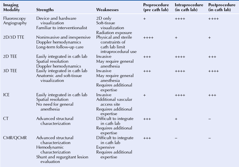
A, Fluoroscopic imaging of a transseptal puncture. In the anteroposterior position the wire (double red arrows) is pulled back from the superior vena cava (SVC) to the right atrium. Using a combination of tactile feedback and fluoroscopic orientation the septum is crossed. B, RT 3D TEE imaging during transseptal puncture. Note the wire (double red arrows) in the right atrium (RA). The arrowhead points to the fossa ovalis, the thinnest area of the septum. The fossa can often have the appearance of a septal defect as a result of echo drop-out. C and D depict biplane TEE imaging of the transseptal puncture in the bicaval (C) and midesophageal 4-chamber (D) views. The catheter “tents” the septum (∗) demarcating the position of puncture.
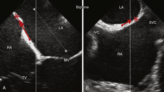
Biplane 2D TEE images of the interatrial septum. A midesophageal 4-chamber view (A) and the corresponding biplane bicaval view (B) of the interatrial septum. The red arrows demonstrate the direction of the ideal septal puncture site (∗) compared to a standard septal puncture site (•), ensuring more navigation room within the left atrium (LA). The additional anteroposterior navigation room within the LA is shown in A (dashed white line).
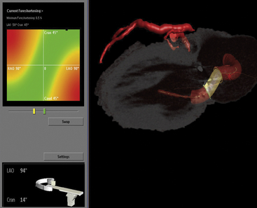
Fusion imaging of CT angiography (CTA) datasets with centerline data for preplanning the optimal fluoroscopic views at the time of percutaneous closure of a mitral paravalvular leak. Rotation of the image data provides the operator a 3D sense of the procedure. The gantry angulation can be predetermined, allowing for selection of an optimal perspective for target navigation without significant overlap of adjacent structures (LAO 94 CRAN 14 in this example). The left anterior descending coronary artery is shown on top (red line) for reference and orientation. The proposed pathway for closure is shown, with the paravalvular leak highlighted in yellow. Simultaneous RT TEE is used intraprocedure for wire positioning. This combined image guidance strategy provides maximal preprocedure and intraprocedural visualization to help successfully complete the task.
2.4 Modality Selection
Fluoroscopy and Angiography
Vascular Closure Procedures
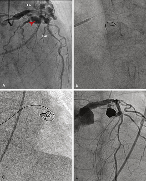
A, Diagnostic angiography reveals a large cavernous fistula (arrowhead) from the left anterior descending (LAD) to the pulmonary artery (PA). Fluoroscopy and cineangiography are used alone to guide the radio-opaque coils into the fistula’s feeder vessel via the antegrade approach (B and C). D, Complete closure of the fistula.
Alcohol Septal Ablation
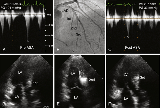
A and C depict post-premature ventricular contraction (PVC) left ventricular outflow gradients before and after ASA. Note that the gradient decreased from 100 mmHg to 30 mmHg. B highlights the first, second, and third septal perforators on this right anterior oblique (RAO) left coronary arteriogram. D, E, and F illustrate septal enhancement at different levels of the interventricular septum corresponding to the septal perforator injected with contrast. Note that injection of the first septal perforator (D) produced enhancement of the septum near its membranous portion; this was considered inappropriately proximal for a successful ablation. The injection of the third septal perforator (F), was considered to be inferior, beyond the point of systolic anterior motion of the mitral valve (SAM). E depicts injection of the second septal perforator, which was at the level of SAM, and was chosen for alcohol ablation.
Echocardiography
Intracardiac Echocardiography
Patent Foramen Ovale Closure
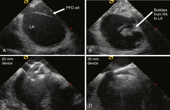
A, ICE image of a large PFO showing the opening created by the thin septum primum unattached to the septum secundum. B, Agitated saline readily crosses from the right atrium (RA) into the left atrium (LA) via the PFO. C, A 25-mm Amplatzer PFO device is inserted; however, with pushing of the delivery cable, the right atrial disc prolapses into the PFO tunnel. D, A 35-mm device is inserted with good capture of the thick septum secundum, providing device stability and closure of the PFO.![]()
Stay updated, free articles. Join our Telegram channel

Full access? Get Clinical Tree


Imaging in Structural Heart Disease