Imaging Artifacts and Pitfalls
Lori B. Heller
An artifact can be defined as any structure in an ultrasound image that does not have a corresponding anatomic tissue structure. Artifacts are a common occurrence in an ultrasound display because they are often the result of the physical properties of ultrasound itself. Recognizing artifacts is essential to proper ultrasound interpretation, because not identifying an artifact as such may lead to unwarranted clinical intervention or concern. Similarly, pitfalls may also cause improper diagnoses. Pitfalls are normal anatomic structures that are often erroneously interpreted as pathologic. This chapter will discuss the detection and avoidance of artifacts, as well as the identification of common echocardiographic pitfalls.
ARTIFACTS
Artifacts may be classified into four main categories: missing structures, degraded images, falsely perceived objects, and structures with a misregistered location.
MISSING STRUCTURES
The absence of an object or area that should be projected on the ultrasound display is considered an artifact. Missing structures occur for several reasons and can be related to the resolution of the ultrasound image. Resolution is defined as the ability to distinguish between two distinct structures that are in close proximity. Lateral resolution, or the ability to distinguish between two objects in a horizontal plane, is related to the bandwidth of the ultrasound beam. If two structures are closer together than the width of the lateral resolution, they will appear as a single image; in essence, the display is missing images. The best lateral resolution occurs at the focal zone, where the near field meets the far field and where the beam width is the narrowest (Fig. 3.1). Longitudinal, or axial, resolution is the ability to distinguish between two structures in the longitudinal direction. Longitudinal resolution is determined by the spatial pulse length. Because the smallest resolvable distance between two reflectors is one wavelength, higher frequency (and therefore shorter wavelength) transducers have greater axial resolution (1). It follows, then, that lower frequency transducers are less able to distinguish two separate objects in the vertical plane.
Acoustic shadowing may also create missing images. It occurs when the ultrasound beam reaches a strong reflector. This reflector decreases the beam intensity to distal structures, essentially blocking the beam to that area. Therefore, any image that lies deep to the strongly reflecting item cannot be seen. It places a shadow (or anechoic) area distal to the original structure. This commonly occurs with high-density structures, such as prosthetic valves, and heavily calcified objects (2). When shadowing occurs, an alternate acoustic window is required to view the objects or areas of interest (Fig. 3.2).
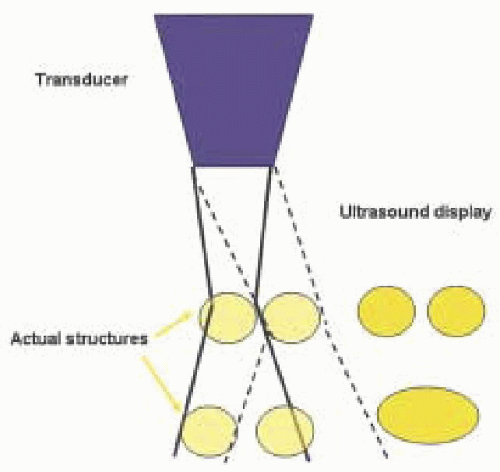 FIGURE 3.1. As the depth increases away from the focal zone, lateral resolution is decreased. Even as the scan line moves laterally, noted by the dotted lines, the two separate objects seen in the far field are unable to be viewed as distinct entities. |
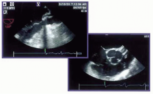 FIGURE 3.2. Shadowing. Left, long axis view of the left ventricle and LVOT demonstrating shadowing through the center of the image. This resulted from a suture line of a bioprosthetic valve. Right, to image the aortic annulus in its entirety, a change in imaging plane from 120 degrees to 30 degrees was required. |
DEGRADED IMAGES
An image of imperfect or poor quality is referred to as degraded and is often due to artifact phenomena. Reverberations are a type of image degradation. They are secondary reflections that occur along the path of a sound pulse and are a result of the ultrasound “bouncing” in between the structure and another reflecting surface. Reverberations appear as parallel yet irregular lines extending from the object away from the transducer. They occur when either the near side of the object, a second object, or the transducer itself functions as another reflecting surface. When the transducer functions as this additional reflector, an image is displayed as expected after the ultrasonic beam is returned to the transducer. However, this same beam is then sent back to the object, reflected back again to the transducer, strikes the transducer face, and is reflected back to the target (Fig. 3.3). These repeated journeys traveled by the same beam produce additional signals that are interpreted as the same object at twice the distance from the primary target. This can occur multiple times, and the result is multiple images displayed on the screen in a straight line from the object away from the transducer. Therefore, a reverberation is two or more equally spaced echo signals at increasing depths, twice the distance as the original signal. Reverberations generally occur with strong, superficial reflectors, such as calcified structures and metallic objects (3). A common site for this is in the descending thoracic aorta and is known as a linear reverberation. More commonly, reverberations are merged together and appear as a solid line directed away from the transducer. This is called comet tail or ring down (Fig. 3.4).
Enhancement is another type of image degradation and is the reciprocal of acoustic shadowing. If a structure is a weak reflector or the medium through which the ultrasound travels has a lower attenuation rate than soft tissue, the beam is attenuated less than normal. The echoes below the weak reflector are then enhanced and these structures appear to be brighter than normal, or hyperechoic (Fig 3.5). This can be adjusted in the vertical plane by decreasing the time-gain compensation on the console.
Noise can also degrade the quality of an image. Noise has many etiologies, including excessive gain and other changes in settings, but in the operating room arena it is most commonly from electrical interference such as electrocautery. Noise appears as very small amplitude echoes on the scan. It is most likely to affect low-level echolucent areas rather than bright echogenic areas (Fig 3.6).
FALSELY PERCEIVED OBJECTS
Falsely perceived objects may occur as a result of refraction. Refracted ultrasound waves are beams that have been deflected from their original uniform path and occur as a result of the waves passing through a medium with a different acoustic impedance. The transducer assumes the reflected signal originated from the initial scan line and the image is displayed as such (Fig. 3.7). Objects may therefore appear laterally or otherwise displaced from their true position and a side-by-side double image is created. A mirror image can also be created as a result of the ultrasound wave bouncing in between the near and the far side of the structure before returning to the transducer, similar to a reverberation. This mirrored image is
always located on a straight line between the transducer and the artifact and is always deeper than the true reflector. A common place of occurrence for this is the descending aorta and is often referred to as a double-barrel aorta (3) (Fig. 3.8). Falsely perceived objects due to refraction and mirror images can often be overcome by altering the scanning angle.
always located on a straight line between the transducer and the artifact and is always deeper than the true reflector. A common place of occurrence for this is the descending aorta and is often referred to as a double-barrel aorta (3) (Fig. 3.8). Falsely perceived objects due to refraction and mirror images can often be overcome by altering the scanning angle.
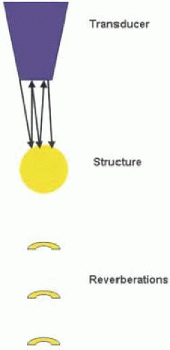 FIGURE 3.3. Reverberation. When the transducer functions as an alternate reflecting source, reverberations appear as parallel yet irregular lines away from the structure. |
MISREGISTERED LOCATIONS
Although the main ultrasound beam is central, multiple beams are projected out from the transducer in a diverging manner (Fig. 3.9). These beams are referred to as side lobes and can result in images being placed in the wrong location on the displayed image. Generally, the energy in these extraneous beams is much less than the main beam and therefore produces no effect or image. However, if
these beams, or side lobes, reach a strong specular reflector, the reflected energy will be added to the reflected energy of the main beam. Side-lobe artifacts usually become apparent when they do not conflict with real, more intense echoes. An enlarged cardiac chamber often provides this setting. If the emitted echo beam is rapidly oscillating, then multiple side-lobe artifacts may be displayed as a curved line at the level of the true object with the brightest area corresponding to the original structure (Fig. 3.10) (1). In the ascending aorta, a side-lobe artifact may create the appearance of a false dissection (Fig. 3.11) (although more commonly, false dissections in the ascending aorta are a reflection artifact related to the left atrium) (4). Identification is accomplished by recognition of the fact that the side-lobe artifacts cross anatomical walls and cavities without regard for natural borders, and always have a common radius from the transducer. They may disappear with adjustment of the depth or angle of the transducer.
these beams, or side lobes, reach a strong specular reflector, the reflected energy will be added to the reflected energy of the main beam. Side-lobe artifacts usually become apparent when they do not conflict with real, more intense echoes. An enlarged cardiac chamber often provides this setting. If the emitted echo beam is rapidly oscillating, then multiple side-lobe artifacts may be displayed as a curved line at the level of the true object with the brightest area corresponding to the original structure (Fig. 3.10) (1). In the ascending aorta, a side-lobe artifact may create the appearance of a false dissection (Fig. 3.11) (although more commonly, false dissections in the ascending aorta are a reflection artifact related to the left atrium) (4). Identification is accomplished by recognition of the fact that the side-lobe artifacts cross anatomical walls and cavities without regard for natural borders, and always have a common radius from the transducer. They may disappear with adjustment of the depth or angle of the transducer.
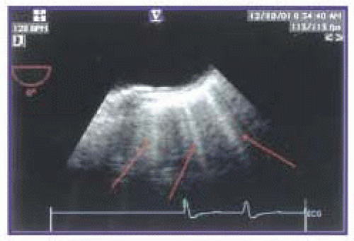 FIGURE 3.4. Reverberation. Merged reverberations form a single line away from the transducer and are called ring-down or comet tail. |
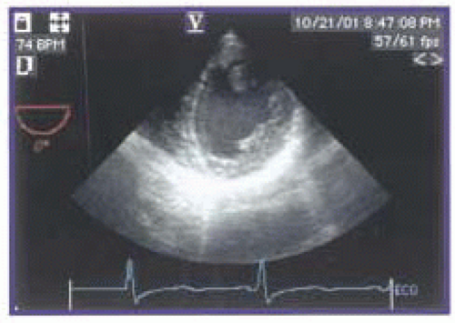 FIGURE 3.5. Enhancement. In this transgastric, short-axis view, enhancement is seen along the anterior wall and anterior pericardium. This can be improved by adjusting the time gain compensation or vertical gain. |
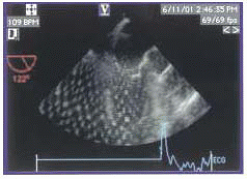 FIGURE 3.6. Noise. Artifact from the electrocautery degrades this midesophageal, long-axis view. |
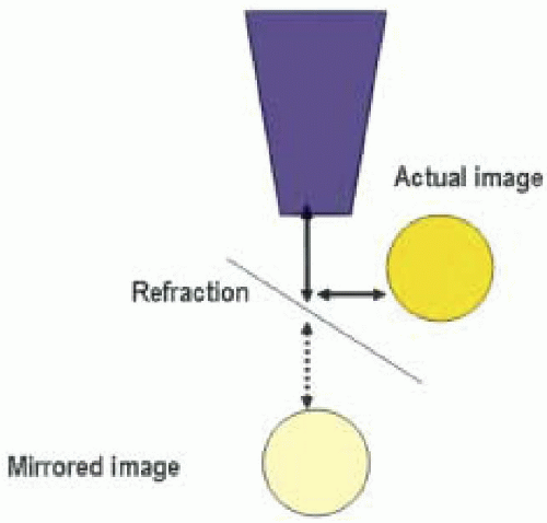 FIGURE 3.7. Refraction. As a result of a change in acoustic impedance of the tissue, some of the sound waves are refracted from their original courses. A false mirror image is then placed distal to the actual object.
Stay updated, free articles. Join our Telegram channel
Full access? Get Clinical Tree
 Get Clinical Tree app for offline access

|