Imaging Artifacts and Pitfalls
Lori B. Heller1
Solomon Aronson1
Lori B. Heller2
Solomon Aronson2
1OUTLINE AUTHORS
2ORIGINAL CHAPTER AUTHORS
▪ KEY POINTS
An artifact is any structure in a display that does not have a corresponding anatomic tissue structure.
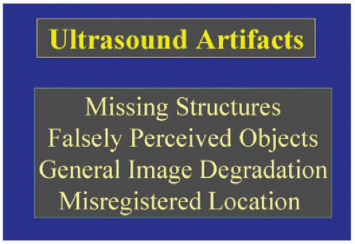
Artifacts can be classified as missing structures, degraded images, falsely perceived objects, and structures in the wrong location (Fig. 2-1).
Artifacts occur as a result of limitations in detail resolution, the properties of ultrasound itself, or equipment malfunction.
Resolution is the ability to distinguish between two distinct structures. Decreased resolution can result in missing structures.
Two common artifacts are acoustic shadowing and reverberation.
Acoustic shadowing occurs when a strong reflector blocks the interpretation of the ultrasound images below it. An alternate window is required to see these structures.
Reverberations are equally spaced image artifacts that appear at increasing depths from the strong reflector being imaged.
Recognizing imaging artifacts and mastering the diagnosis of common echocardiograph pitfalls are essential parts of echocardiography.
Sound is a mechanical vibration in a physical medium.
An artifact can be defined as any structure in an ultrasound image that does not have a corresponding anatomic tissue structure.
I. MISSING IMAGES
Resolution is defined as the ability to distinguish between two distinct structures
that are in close proximity.
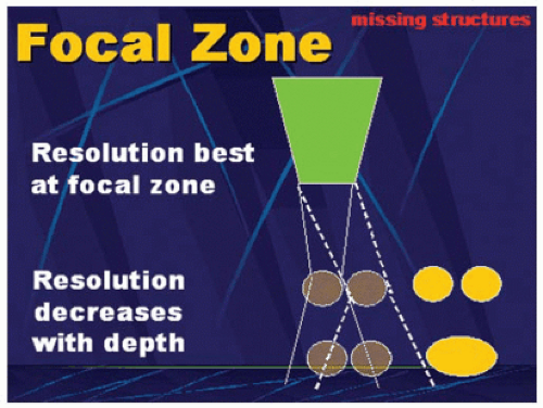
Lateral resolution, or the ability to distinguish between two objects in a horizontal plane, is related to the bandwidth of the ultrasound beam. If two structures are closer together than the width of the lateral resolution, they will appear as a single image; in essence, the display is missing images.
The best lateral resolution occurs at the focal zone, where the near field meets the far field and where the beam width is the narrowest (Fig. 2-2). Missing images due to poor lateral resolution often occur in the distal part of the imaging sector.
Acoustic shadowing also creates missing images (Fig. 2-3). It occurs when the ultrasound beam reaches a strong reflector. This reflector decreases the beam intensity to distal structures, essentially blocking the beam to that area. Therefore, any image that lies deep in relation to the strongly reflecting item cannot be seen. It places a shadow (or anechoic) area distal to the original structure.
This aortic valve (Video 2-1) has been replaced by tissue prosthesis, and the sutures and pledgets around the annulus have caused a large shadow obscuring the leaflets, the LVOT, and the distal tissue.
When shadowing occurs, an alternate acoustic window is required to view the objects or areas of interest.
II. DEGRADED AND FALSELY PERCEIVED IMAGES
A. Reverberations
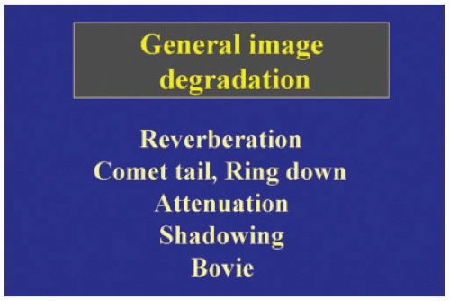
An image of imperfect or poor quality is referred to as degraded and is often due to artifact phenomena. Reverberations are a type of image degradation (Video 2-2).
They are the result of the repeated reflections of two strong specular reflectors. They can occur from two reflectors in the imaging sector or between one reflector and the face of the ultrasound transducer.
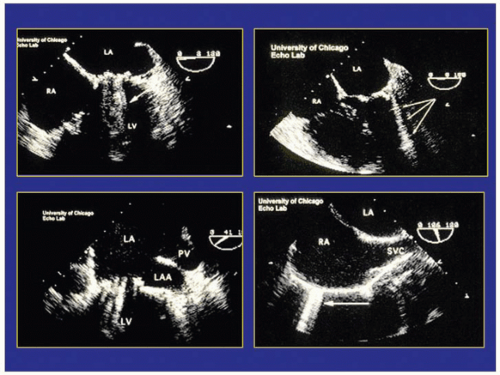
Examples of reverberations (comet tail, ringdown) are represented in Figure 2-4.
In the first instance, linear densities are seen distal to the image, stacked up like Venetian blinds. These linear densities are often fused together and appear to form a single line projecting away from the transducer (Video 2-3).
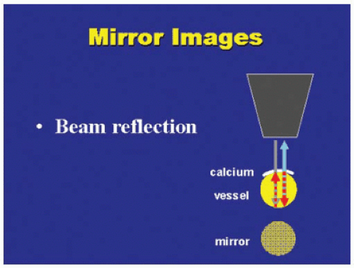
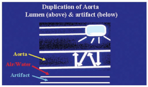
A mirror image is another type of reverberation and can occur when the transducer face itself acts as a reflecting surface. A mirror image can be classified as a falsely perceived image. The descending aorta, in both its transverse and longitudinal scans, often creates this mirror image—commonly referred to as a double-barrel aorta. In Figure 2-5, both types of reverberations are seen (Video 2-4; Figs. 2-6 and 2-7).
B. Enhancement
Stay updated, free articles. Join our Telegram channel

Full access? Get Clinical Tree


