Fig. 7.1
Breathing motion artifacts with two different phase-orders. This figure shows the artifacts caused by changes in respiratory position at different times during a breath-hold acquisition for an interleaved (top) and sequential (bottom) phase-order. (a) Shows an interleaved segmented phase-order (as used in a black blood TSE sequence but reduced to only 24 phase-encode lines for illustration), with 4 segments each with 6 phase-encode lines. Each line-type represents a different cardiac-cycle of data. (b) The effects of a respiratory movement in the middle of the acquisition. (c) The effects of a respiratory movement at the end of the acquisition. (d) A good breath-hold. With interleaved acquisition, respiratory motion at any time during the scan is liable to cause ghosting across the entire phase-encode FOV. (e) Shows a block sequential phase-order case (as used in a cine bSSFP sequence and again only 24 phase-encodes for illustration), with 4 segments each with 6 phase-encode lines. Each line-type represents a different cardiac-cycle of data. (f) The effects of a respiratory movement in the middle of the acquisition. (g) The effects of a respiratory movement at the end of the acquisition. (h) A good breath-hold. With a block sequential phase order the central region of k-space is acquired during a certain well defined period, and not spread throughout the whole acquisition window, therefore if no respiratory motion happens during this period, the artifacts are less conspicuous
Different segmented sequences have different optimal phase-encoding orders, and therefore will be affected by respiratory motion differently. Generally, to avoid sudden signal amplitude and or phase discontinuities through k-space, which would lead to other artifacts, the Turbo-Spin-Echo (TSE) and conventional gradient echo sequences acquire the data with an interleaved manner, whereas for other reasons the balanced Steady-State Free Precession (SSFP) cine sequences acquire in a block sequential manner. However, it should be noted that the exact acquisition methods might vary between manufacturers and even for the same manufacturer over time.
To avoid breathing motion artifacts, the total imaging time is kept short, and suitable for a breath-hold. If the patient is unable to hold their breath, the total imaging time needs to be reduced. Possible solutions include end-inspiratory breath-holds risking greater variability, or the use of parallel imaging, although the reduction of SNR in some applications such as Late-Gadolinium Enhancement (LGE) imaging may prohibit this; or the reduction of overall k-space lines acquired, thus reducing phase-encode spatial-resolution. Another solution that may be available is to reduce the temporal-resolution, by increasing the data lines per cardiac cycle and the imaging window of each cardiac-phase. This may have the cost of increasing cardiac motion problems, especially if imaging during rapid cardiac motion stages.
Breathing motion is one of the biggest challenges of MR coronary angiography. During cardiac motion, the coronaries have been shown to shift position from 5 to 20 mm [1], therefore the imaging window is limited to mid-diastole when the heart is relatively still. 3D coronary angiography imaging is performed during free-breathing and uses navigator echo techniques to monitor respiratory motion.
In general if imaging during a breath-hold, a saturation band can be positioned over the anterior chest wall to suppress any motion induced ghosting from it, if the breath-hold is imperfect.
Cardiac Motion
Cardiac motion is another source of inter-view motion artifacts. Cardiac motion is mainly a problem in sequences where the data acquisition window includes periods of rapid cardiac motion. This is commonly an issue for first-pass myocardial perfusion imaging, where several images are fully acquired during each heartbeat; therefore image acquisition windows are long and spread across the whole of the cardiac cycle, including rapid cardiac motion stages. The heart will go through contraction and expansion as different phase-encode lines are acquired; motion happens both in-plane and through-plane, resulting in artifacts. Acquisition windows for one perfusion image at typical in-plane resolution around 2.5 mm are approximately 100 ms for Gradient-Recalled Echo (GRE) and bSSFP sequences and 70 ms for h-EPI, with parallel imaging with an acceleration factor of 2.
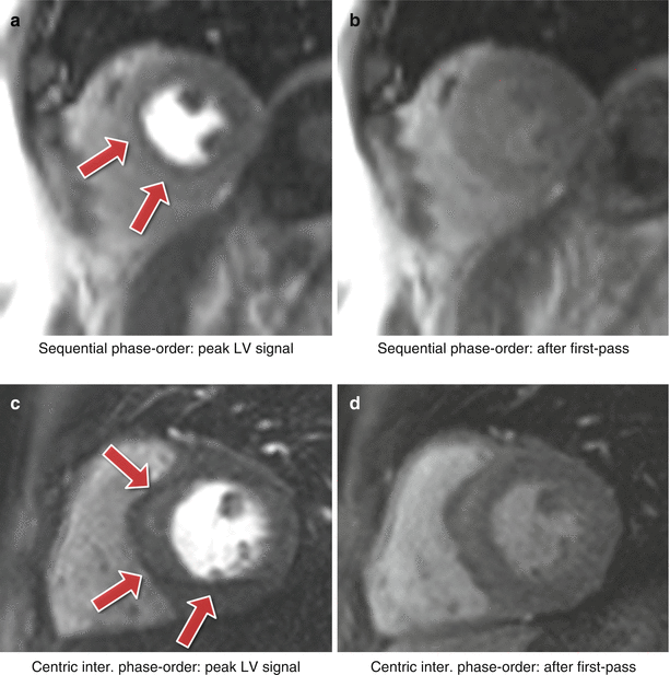
For a Cartesian sequential phase-order, as typically employed in GRE and bSSFP sequences, a continuous motion results in banding artifacts next to sharp edges [2], shown in Fig. 7.2a, b. The appearance of these artifacts is similar to Gibbs ringing artifacts (described later). Alternatively the hybrid Echo-Planar Imaging (h-EPI) perfusion sequence is commonly used with a centric interleaved phase-order tailored for perfusion, minimising the effective TE, resulting in a dark ghosting of the endocardial border along the phase-encode direction (Fig. 7.2c, d).


Fig. 7.2
Myocardial perfusion and cardiac motion artifacts for sequential and centric interleaved phase-orders. (a) In vivo short-axis image of a perfusion scan with a bSSFP sequence with a sequential phase-order acquisition. A subendocardial dark rim artifact is visible likely to be a superposition of motion and Gibbs ringing artifacts (arrows). (b) Same as a but after first-pass; the contrast between the LV and myocardial signal is reduced and the dark rim artifact is no longer visible. (c) In vivo short-axis image of a perfusion scan with an h-EPI sequence with a centric-interleaved phase-order acquisition. A typical motion artifact is visible in the septal wall. This is no longer a subendocardial dark rim as shown in a, but ghosting from the endocardial border offset along the phase-encode direction (arrows). (d) As in b, motion artifacts are no longer visible after first-pass due to the reduction of signal contrast between the LV and myocardium (Video 7.1)
For the GRE and bSSFP sequences with a sequential phase-order, motion induced ringing artifacts can be superimposed with Gibbs ringing and possibly mimic real subendocardial perfusion defects during first-pass. The h-EPI sequence is more robust to motion artifacts, not only because it is the fastest of the three sequences, but also because of its different phase-order (centric interleaved); cardiac motion artifacts do not result in subendocardial dark rim artifacts. Whilst the h-EPI sequence is therefore useful to differentiate cardiac motion artifacts this also makes it very sensitive to frequency-offsets as described below.
As the motion ringing magnitude is dependent on the signal difference across the edges, motion artifacts are expected to be problematic during first-pass when there is a large contrast between the LV blood pool and the myocardium.
In general, whatever the k-space acquisition scheme, in order to minimise cardiac motion artifacts it is important to keep the image acquisition time as short as possible in each heartbeat and if possible aim for timings of the heart cycle where the heart is relatively still. Additional approaches include using a fast EPI readout, and/or parallel imaging.
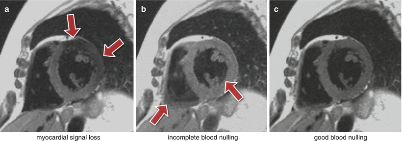
The inversion pulse preparations used in dark-blood imaging or LGE are particularly sensitive to cardiac motion and arrhythmias. For the multiple inversion pulse preparation used in dark-blood imaging, a correct cardiac cycle synchronisation with the readout is important. If during image acquisition, the heart is not in the same position as when the double-inversion pulses were applied, then the myocardial signal can be affected resulting in myocardial signal loss (Fig. 7.3a). To reduce the potential for this the spatially selective inversion pulse thickness is commonly larger than the image-slice thickness by a factor of 2 or 3. The trade-off is the re-inversion of blood outside the image-slice potentially reducing the blood signal nulling efficiency for slow flow, which may be a factor for patients with an abnormally low cardiac function. Another reason for reduced blood signal nulling efficiency would be an inversion time that was either too long or too short (Fig. 7.3b). Although it is not always possible to change all the parameters required, it is normally possible to adjust the trigger delay and inversion time to change the timings of the preparation and imaging. It should be noted that the terminologies for these timing parameters vary between manufacturers.


Fig. 7.3
Dark-blood imaging with cardiac motion artifacts. (a) Myocardial signal loss (arrows) due to incomplete re-inversion of the myocardial magnetisation. (b) Partial blood signal (arrows) due to incorrect inversion-recovery timing not coinciding exactly with the “null” time of the blood magnetisation. (c) Good blood signal nulling, without loss of myocardial signal. In this last example the inversion pulse thickness and timing were optimal for darkening the blood signal
Arrhythmias in LGE can lead to poor image quality due to contrast inconsistencies between different k-space segments, due to variations in the TR for the inversion recovery sequence. This leads to different amounts of recovery and therefore different levels of magnetisation before and after the inversion pulse. For this reason data is usually acquired for every other heart-beat, reducing dependency on a regular heart cycle but increasing imaging time (Fig. 7.4). For patients with very fast heart-rates it might be required to trigger every three heart-cycles in order to guarantee good image quality.


Fig. 7.4
Arrhythmia artifacts in LGE.LGE short-axis image, in a patient with arrhythmia. (a) Image acquisition for every heart-cycle. (b) Image acquisition for every other heart-cycle. Image quality is improved in b by acquiring data at every other heart-cycle only, reducing the contrast inconsistencies between different k-space segments that were created by the irregular heart-rate
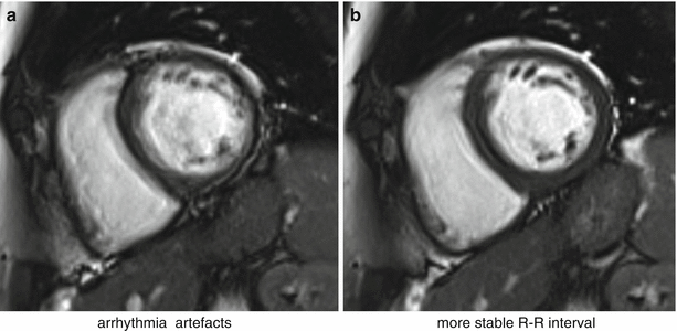
Poor cardiac triggering can also result in motion artifacts. Most cardiac imaging techniques require the acquisition of full images or k-space segments at specific cardiac phases, i.e. at specific times after the R-wave. Poor triggering due to patients with arrhythmias or weak ECG signal, or due to magneto-hydrodynamic [3] (generation of an electric field due to ions in blood flowing across the main magnetic field) and/or gradient pulse distortion, can cause effects varying from minor inconsistencies to conspicuous artifacts. For example, poor triggering in myocardial perfusion imaging typically results in slices at different cardiac phases per cycle of the perfusion first-pass series; this may not degrade the image quality of each individual image but it affects the clinical interpretation of first-pass and severely complicates segmentation in quantitative analysis. Triggering problems in cine imaging tend to result in more severe artifacts because each image frame’s k-space is segmented across multiple heart-cycles. Mis-triggers causing jumps in TR and or heart-cycle variations will create inconsistencies between k-space segments, thus leading to noticeable cardiac motion artifacts (Fig. 7.5). If ECG triggering quality is low, alternatives can be used such as pulse oximeters, although care must be taken with the fact that the pulse cycle is delayed relative to the heart-cycle and not as well defined, thus reducing timing precision. More recently real-time imaging strategies have been developed where the requirement of ECG triggering and/or breath-holding are relaxed [4].


Fig. 7.5
bSSFP cine and arrhythmia. Short-axis bSSFP cine frame imaged twice: (a) with significant arrhythmia artifacts and (b) with reduced artifacts due to a more stable RR-interval (Video 7.2)
Blood Flow
Flowing blood has historically been a source of artifacts on CMR images. For conventional sequences the movement of blood results in a signal phase shift related to the velocity of the blood flow. This would not cause a major problem if the blood flow was exactly the same on each successive cardiac cycle of the scan; however, this is not usually the case and the result is that this changing velocity related phase shift will add to and corrupt the spatial phase encoding in such a way that the Fourier transformation will interpret the blood signal as coming from a range of locations spread across the image along the phase-encode direction. To avoid this problem in the early days of CMR for spin-echo acquisitions the images were often acquired in systole, when two factors combined to cause a loss of blood signal. Firstly, the blood flow was fast causing increased phase shifts leading to a broad phase distribution at a voxel scale known as intra-voxel phase dispersion, and secondly time-of-flight effects meant that the same blood was not excited by both the slice selective 90° and 180° pulses (Fig. 7.6a, b). With the introduction of faster segmented acquisitions of spin-echo images with double inversion blood signal nulling, this problem was largely removed (Fig. 7.6c), although residual static blood at ventricular trabeculations is commonly visible as a white layer in the left ventricle (Fig. 7.6d).


Fig. 7.6
Spin-echo blood flow artifacts. (a, b) An old example of blood flow artifacts on a conventional spin-echo sequence of a transverse slice through the great vessels above the heart: (a) image acquired in diastole, (b) image acquired in systole showing reduced flow artifacts due to increased intra-voxel dephasing and time of flight effects. (c) Similar transverse plane to a-b, acquired with a HASTE sequence in diastole. The introduction of faster segmented acquisitions with black blood preparation avoids flow artifacts in diastole; multiple spin-echo sequences (HASTE, FSE) are generally reliable only in diastasis. (d) Dark-blood prepared FSE image (with STIR fat suppression) shows residual slowly moving blood signal (arrow) that was re-inverted by the double inversion preparation pulse and did not wash out between preparation and imaging
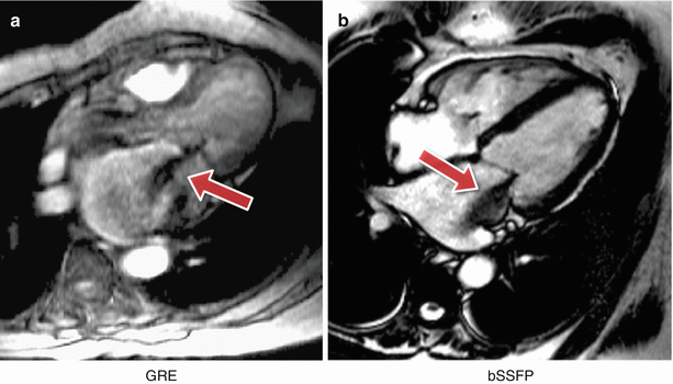
For gradient-echo acquisitions in the early days the problem was largely removed by the introduction of velocity or flow compensation to null velocity related phase shifts. With the introduction of faster gradient performance and shorter TE’s and consequently greatly reduced velocity related phase shifts, the potential for these artifacts has been reduced. Nonetheless velocity compensation remains an option to minimise the problem. However, as a consequence of some cardiovascular diseases, the blood flow often becomes much more complex and turbulent and contains higher orders of motion than simple velocity, (acceleration, jerk, etc.). These higher orders of flow motion can introduce phase shifts even to a velocity compensated sequence and the spatial scale of this motion is such that this can also lead to significant phase dispersion. This intra-voxel phase dispersion effect is dependent on the TE. Although this signal loss artifact has been found useful by some to assess the severity and form of defective heart valves (Fig. 7.7) it should be used with caution as the area of signal loss may not be directly related to the severity of the valve stenosis.


Fig. 7.7
Complex flow signal loss. Two examples of a systolic frame of an horizontal long axis cine acquisition from two different patients with insufficient mitral valves: (a) GRE, (b) bSSFP. The jet of signal loss caused by complex flows in the left atrium suggests mitral valve regurgitation (arrows)
Gibbs Ringing
Gibbs ringing, also known as a truncation artifact, is present in every unfiltered MRI image and results from the fact that there is only enough time to acquire a finite region of k-space for each image. When the sampled signal is truncated at the k-space edge and then this k-space is inverse Fourier transformed into the image, ringing will unavoidably be present at high-contrast sharp edges of structures on the image. The ringing is a known mathematical limitation of the Fourier transform.
The 2 pixels both sides of and closest to the edge will show a maximal undershoot and overshoot of the true signal. The magnitude of the under/overshoot can be shown mathematically to be approximately 9 % of the edge signal difference; the ringing magnitude is thus dependent on the signal difference at the edge, the higher the signal discontinuity the higher the under/overshoot (Fig. 7.8a, b). Gibbs ringing also scales with pixel size, i.e. the higher the spatial-resolution the thinner the ringing, but the under/overshoot magnitude does not change with spatial-resolution. The ringing visibility is also dependent on the edge position inside the pixel [5] (unless zero-filling is applied in k-space for interpolation, making Gibbs more consistent).


Fig. 7.8
Gibbs ringing. (a, b) In vivo short-axis first-pass perfusion example: (a) circumferential Gibbs ringing during the first-pass of contrast (arrows); (b) the same short-axis plane after the first-pass when Gibbs ringing is no longer noticeable. (c) Example of Gibbs ringing in a short-axis frame of a bSSFP cine (arrow)
Gibbs ringing is present in all unfiltered MRI images, but it is especially problematic in certain applications such as myocardial first-pass perfusion studies where the spatial-resolution is low to reduce acquisition time. Gibbs ringing can mimic a real subendocardial perfusion defect during first-pass due to the large signal discontinuity between the bright LV blood pool and the darker myocardium [6].
One way of reducing Gibbs artifacts is by filtering the k-space data of the image, a process usually known as apodization. Hamming and Hann filters are commonly used in image and signal processing to reduce Gibbs ringing artifacts, although at the penalty of reducing spatial-resolution. Due to the image constraints of most cardiac imaging protocols, any further loss in spatial-resolution may affect diagnostic confidence and is therefore seldom used. It is then perhaps better for clinical diagnosis and image interpretation to be performed with some understanding of the characteristics of these artifacts and can discriminate between them and true perfusion defects (which is sometimes ambiguous, especially for mild perfusion defects). The access to k-space filtering options in the scanner’s protocol may vary for different manufacturers.
< div class='tao-gold-member'>
Only gold members can continue reading. Log In or Register to continue
Stay updated, free articles. Join our Telegram channel

Full access? Get Clinical Tree


