Fig. 39.1
A large mid-muscular VSD delineated with epicardial echocardiography in a 4.8 kg patient. Epicardial echo can be useful as the probe can be used to mimic the desired angle and direction for the wire and sheath passage. RV right ventricle, LV left ventricle
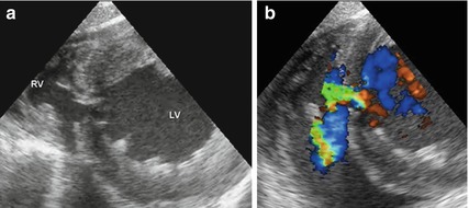
Fig. 39.2
TOE view of a moderate mid-muscular VSD with 2D imaging (a) and colour flow Doppler (b). Note that the TOE view gives a less ‘surgical orientation’ of the defect and requires more spatial awareness from the operators compared with the epicardial scan. RV right ventricle, LV left ventricle
2.
When the cardiac position and connections are normal, a sternotomy will usually be the correct approach; however, a thoracotomy or subxiphoid approach may be used in cases where the anatomical orientation is favourable. Exposure of the right ventricular surface is usually adequate, allowing a “limited” sternotomy to be used. Cardiopulmonary bypass should not be necessary in uncomplicated cases.
3.
After locating and delineating the defect on TOE, the correct position to puncture the right ventricle is identified. A combination of angle towards the septum, cavity space for device deployment, proximity to the moderator band and the space constraints for the operators to manipulate the catheters and sheaths needs to be considered. Practically, this is done by indenting different parts of the RV free wall with a finger while observing the TOE image.
4.
Prior to puncturing the RV, the occlusion device is selected, prepared and loaded, ready for insertion into the sheath. The correct device size usually has a waist diameter of 2 mm larger than the maximum measured diameter of the defect. The most frequently used device is the St. Jude AMPLATZER Muscular VSD Occluder; however, VSD occluders by other manufacturers are available. In certain anatomical variants, other device designs such as that used for patent ductus occlusion may be more appropriate although this would be “off-label” use.
5.
A purse string is placed on the RV free wall and heparin 100 units/kg is administered. Under TOE guidance the RV is punctured with an 18 g needle and a 0.035″ Terumo J-Tip hydrophilic guidewire guided across the defect into the LV cavity. The guidewire is ideally directed out the left ventricular outflow tract to avoid interference with the mitral papillary muscles and away from the posterior wall of the LV. A short (7.5–15 cm) sheath, large enough (usually 6–10 F) to accommodate the chosen device, is advanced over the wire and across the VSD to the LV cavity (Fig. 39.3). Depending on the anatomy, the VSD may be difficult to cross with the puncture needle and wire. Although attempting to direct the wire with a catheter and wire combination, it is likely that the RV free wall puncture point is suboptimal and needs to be redone. A perpendicular approach from the free wall to the ventricular septum is required so as not to distort the anatomy and enable successful deployment.
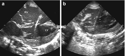
Fig. 39.3
With epicardial imaging the defect shown in Fig. 39.1 has been crossed with the sheath and wire and this has been followed with the dilator and sheath, delineated by the asterisks (a). After the dilator and wire have been removed, the ‘train-track’ appearance of the empty sheath is seen (b). RV right ventricle, LV left ventricle
6.
Using TOE guidance, the LV disc is deployed in the mid-cavity and withdrawn to oppose the disc onto the septum (Fig. 39.4). The waist of the device and subsequently the RV disc are uncovered by withdrawal of the sheath. Several attempts may be needed to conform the RV disc correctly; it is therefore important not to pull the sheath out of the RV during the initial deployment. Indeed the RV disc may not completely conform on the RV septal aspect due to trabeculations, moderator band and limited chamber size near the apex. The operators must then decide whether the RV disc has formed adequately to allow defect occlusion and device stability even if it looks constrained (Fig. 39.5).
 < div class='tao-gold-member'>


Only gold members can continue reading. Log In or Register to continue
Stay updated, free articles. Join our Telegram channel
Full access? Get Clinical Tree
