(6.1)
where SNRp is the SNR when parallel imaging rate R is used, SNRo is the original SNR without parallel imaging, and g is the so-called g-factor of the coil, which is related to its design and geometry. By going from 1.5 to 3 T, the 2× SNR gain may be traded for a 4× scan time reduction. In practice, the g-factor of the coils (which increases with acceleration factor) would limit these theoretical gains.
The spin-spin relaxation time, T2, is relatively insensitive to B0, while the T1 (the spin-lattice relaxation time) increases with field strength [5]. This can be another advantage of high field imaging in some CMR applications, especially when T1-shortening contrast agents are used. The longer T1 values at high field lead to larger T1 differences between tissues, and this translates into improved T1 contrast. Tissue suppression is improved at high field because tissues driven to saturation take longer to recover longitudinal magnetization. Table 6.1 shows the T1 values of blood and myocardium at 1.5 and 3 T.
Table 6.1
The T1 values of the myocardium and blood at two different field strengths from one study (cf. [6])
1.5 T | 3 T | |
|---|---|---|
Myocardium | 1030 ± 34 ms | 1471 ± 31 ms |
Blood | 1441 ± 120 ms | 1932 ± 85 ms |
Experiments have shown that the relaxivities of Gd-DTPA at 1.5 T and 3 T were similar (4.79 ± 0.08/mM/s and 4.5 ± 0.05/mM/s respectively) for concentrations between 0.1 and 5 mM [8]. Since the T1 times of unenhanced tissues at 3 T are longer than those at 1.5 T, the same dose of gadolinium based contrast agent often produces a stronger signal change in contrast studies at 3 T. This means that to achieve the same contrast change at 3 T, gadolinium contrast dosage may be reduced.
Hydrocarbons such as lipids can have complex chemical structures and the Larmor frequency of hydrogen nuclei in these molecules is close to but often not equal to that of water protons. This is known as “chemical shift”, described in ppm (parts per million) of the Larmor frequency, and is intrinsic to a specific chemical species. The absolute value of the chemical shift increases with B0. For instance, lipid has a chemical shift of −3.5 ppm. At 1.5 T, this translates into a resonance frequency for lipid that is 220 Hz lower than that of water protons; this frequency difference increases to 440 Hz at 3 T. Metabolites in the body with different chemical shifts therefore have increased frequency separation at high field. Together with higher SNR, higher field strength benefits MR spectroscopy as it allows better distinction of spectral peaks of various metabolites.
Susceptibility is the degree to which a material is magnetized in response to an applied B0. In the body, oxygenated blood is diamagnetic while deoxygenated blood is paramagnetic; when the oxygen concentration in blood changes, its susceptibility changes, and its MR signal changes as well. This contrast mechanism is called BOLD (blood oxygenation level dependent contrast). As the absolute susceptibility change increases with B0, CMR techniques based on BOLD can benefit from high B0.
Challenges of High Field MRI
One major challenge of diagnostic imaging at high field is patient safety. When B0 increases, the risk to patients with implanted cardio defibrillators (ICDs) or other implants increases accordingly. Currently, safety studies on implantable devices have mostly been performed using 1.5 T systems. Only a few studies have looked into the risks of implantable devices at 3 T [9–11], and there have been no similar published investigations yet at 7 T. Whether the risks to patients with implants can be justified for the benefits of imaging at 3 T and beyond remains an open question.
Another safety concern is the increased energy deposition at high field. When RF pulses are applied during imaging, energy is deposited into the body. Such RF energy is absorbed by the body and results in tissue heating. Energy deposition to the body is described by the Specific Absorption Ratio (SAR) and it is proportional to the square of the Larmor frequency (and hence B0). As such, SAR will be increased four times when the same imaging sequence applied at 1.5 T is used in 3 T. SAR may be reduced through special RF pulse design such as VERSE [12], but it remains an important limiting factor for RF intensive sequences like FSE, HASTE, and balanced SSFP.
Robust ECG triggering is more difficult at high B0. When a person lies in the scanner, the static B0 field interacts with the ions in the flowing blood and induces voltage (due to the magnetodynamic effect) that can contaminate the ECG signal detected at the body surface [13]. Due to the timing of peak blood flow in the aorta, the T wave in the ECG appears to be elevated, and can be mistaken for the QRS wave. At 1.5 T, vectorcardiography can be used to detect QRS complexes reliably. At higher B0, the magnetodynamic effect becomes more pronounced and robust detection of QRS complexes becomes difficult. Special techniques may be needed at high field to ensure reliable ECG triggering [14].
Magnetic field inhomogeneity is usually described in terms of ppm (parts per million) relative to B0; thus 1 ppm at 1.5 T (Larmor frequency = 64 MHz) is equivalent to a 64 Hz frequency offset, while 1 ppm at 3.0 T is equivalent to a 128 Hz offset. This means that field inhomogeneity in absolute terms over a specific volume at 1.5 T would be two times worse at 3 T within the same volume. Off-resonance effects on image quality are typically more severe at high field. Balanced SSFP (bSSFP, aka trueFISP), a workhorse pulse sequence for CMR at 1.5 T, is more prone to banding artifacts due to the increased field inhomogeneity at 3.0 T. Flow artifacts also appear more often in balanced SSFP images (see Fig. 6.1) at high field. Certain k-space traversal schemes such as the spiral trajectory that is more sensitive to off-resonance can suffer from increased artifacts as well. To achieve a homogeneous B0 field at 3 T, shimming is critically important.
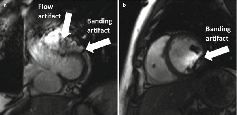
Fig. 6.1
Balanced SSFP artifacts at 3 T. (a) The flow artifact at the outflow tract and the banding artifact at the myocardium. (b) Typical banding artifact in the short axis cine of a mid-ventricular slice
Transmit field inhomogeneity, or B1+ field inhomogeneity, is another major challenge for CMR at high field. When an RF excitation pulse is applied, an electromagnetic wave at the Larmor frequency is transmitted to the body that tips the water protons into the transverse plane. This wave travels in the body at a speed determined by tissue conductivity. The frequency, f, of this electromagnetic wave increases with B0. As B0 increases, the dielectric constants of tissues decrease, which leads to a decrease in the velocity, v, of the electromagnetic wave travelling inside the body [15]. The net result is that the wavelength of the RF field, λ, decreases (since v = f λ). At 3 T and above, λ becomes comparable in length to the size of the organs being imaged. Constructive or destructive interference can occur when such electromagnetic waves propagate through the different organs of the body (similar to light refraction). As a result, the flip angle produced by an RF pulse will vary spatially as spins at different locations are tipped differently, and images suffer from signal inhomogeneity [16] (see Fig. 6.2). The uneven distribution of energy throughout the body may also result in local heating. RF shimming and parallel transmit technology have been proposed to address these problems. Recent studies show that using two independent transmit channels, B1+ field inhomogeneity can be reduced and image quality is improved in CMR applications at 3 T [17].
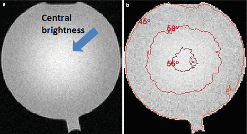
Fig. 6.2
RF field inhomogeneity at 3 T. (a) A phantom image acquired on a 3 T system using the body coil for both transmission and reception. This is a gradient echo image acquired with a flip angle of 45°. The image has non-uniform signal distribution. (b) The actual flip angle distribution in the experiment. The signal non-uniformity is caused by B1+ field inhomogeneity. Here, the flip angle distribution was obtained using DAM (double angle method) and median filtered. At the image center, the effective flip angle exceeds 55°
Frequency dispersion at tissue interfaces due to tissue susceptibility differences increases with field strength and results in more signal loss (and distortion in the case of EPI) because of increased signal dephasing. This is particularly problematic at the heart-lung interface [19]. This signal loss is commonly observed in bSSFP images (see Fig. 6.1), and in first pass perfusion images using EPI.
Local field inhomogeneity increases at high field. As a result, the T2* values of tissues at 3 T are lower than those at 1.5 T. Storey et al. [18] showed that changes in 1/T2* (=R2*) values of the heart and liver caused by iron burden are linearly related to field strength.
The increased T1 at 3 T also has its downside in some cases. In gradient echo imaging, signal is approximately proportional to √(TR/T1) at the Ernst angle [20]. In bSSFP, the signal varies with √(T2/T1). In both cases, longer T1 reduces the MR signal and hence the overall SNR gain achievable at 3 T. In spin-echo based sequences, TR must be increased for good T2/PD contrast at high field, resulting in increased scan times. In most cases, optimal imaging parameters for 1.5 T and for 3 T are different due to differences in T1, field homogeneity, SAR, and SNR.
Despite the increased frequency separation between fat and water protons, fat saturation is more challenging at high field due to increased B0 inhomogeneity. In the case of selective water excitation (composite) pulses, the higher fat-water difference in frequency at high field reduces the time interval between two RF pulses at which water and lipid protons go out-of-phase. Selective pulses with shorter duration are needed and may compromise slice profile and increase the SAR values.
The faster precession frequency at high B0 also means that the TEs for in-phase and out-of-phase images in gradient echo based techniques are closer. Multipoint Dixon methods used for fat-water separation (such as [21]) require different choices of TEs if multiple echoes are acquired in one TR period.
CMR Applications at High Field
When going from 1.5 T to 3 T or higher field strength, the changes in MR properties of body tissues, and changes in other physical parameters, may benefit some CMR applications while making other CMR techniques challenging.
The main advantage that high field MR systems offer is higher SNR. This SNR advantage allows for higher readout bandwidth, reducing echo spacing, and hence shorter acquisition time.
Another way to exploit the SNR advantage at 3 T is by parallel imaging [22, 23] – see Eq. 6.1. This advantage applies to most CMR applications. For instance, when using single-shot FSE (aka HASTE) at 3 T, parallel imaging reduces the number of echoes and thus the SAR of the sequence. It also improves image sharpness.
Balanced SSFP (or trueFISP) provides exceptional contrast between blood and myocardium in cine imaging [24] and has been the workhorse of CMR at 1.5 T. Combined with parallel imaging, patient breathhold time can be reduced. However, the technique is sensitive to field inhomogeneity, particularly at the heart-liver-lung interface [25]; the situation is worse at 3 T [26]. Quite some effort has been made to address the above issues in the past several years. Improved shimming becomes a necessity for bSSFP to work robustly at 3 T. A frequency scout technique has also been proposed to address this issue [27]. In this method, single-shot bSSFP images are acquired over multiple heartbeats, each using a resonance frequency slightly shifted (e.g., 50 Hz, 100 Hz, and so on) from the center frequency. The frequency offset that corresponds to the image with the best image quality will be the off-resonance frequency adjustment that needs to be applied to subsequent bSSFP acquisitions (Fig. 6.3).
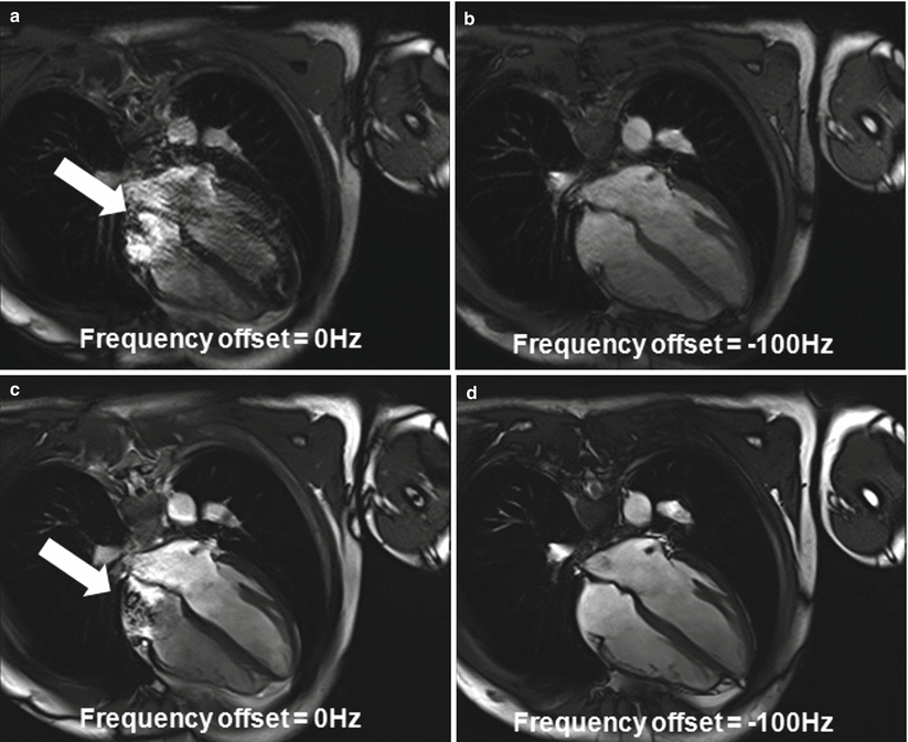
Fig. 6.3
The use of frequency scout to reduce the effects of B0 field inhomogeneity at 3 T. The frequency scout images in (a, b) show the effect of varying the frequency offset on bSSFP image quality. (c, d) The bSSFP cine images acquired using the corresponding frequency offsets. Note that the image contrast in (a, b), acquired using a single shot technique, is not the same as (c), which was acquired under steady state
Balanced SSFP for cines that have reduced sensitivity to B0 inhomongeneity (and reduced sampling efficiency) have also been proposed [28]. Alternatively, sensitivity to B0 inhomogeneity may be minimized by reducing TR by reducing spatial resolution and increasing receiver bandwidth.
Real time cine with adequate image quality has been challenging to achieve at 1.5 T due to the SNR impact from the use of fast imaging. The SNR increase at 3 T makes real time imaging more practical. Equation 6.1 shows theoretically that parallel imaging with acceleration rate 4 at 3 T is possible if the g-factor is small. Matched with appropriate coils, appropriate k-space trajectories, and advanced reconstruction algorithms, the g-factor and the SNR penalty due to high acceleration factors can be kept small. Recent work has shown that real time cine at 3 T can achieve a temporal resolution as high as 20 ms at a spatial resolution of 2 × 2 × 8 mm [29].
Readout using balanced SSFP is both time and SNR efficient compared to turboFLASH, and it is commonly used with parallel imaging in single-shot techniques at 1.5 T. At 3 T, the use of bSSFP for readout is limited by its increased sensitivity to B0 inhomogeneity, therefore a FLASH readout is often preferred. At high magnetic field, short TR and high bandwidth can be used with FLASH readout while maintaining adequate SNR.
Flow imaging is another application that benefits from the higher SNR at 3 T in a direct way, and parallel imaging can be used in the same way as in cine imaging to reduce scan time.
Late gadolinium enhancement (LGE) for infarct imaging using inversion recovery turboFLASH also benefits directly from the higher SNR at 3 T. Breath-hold time can be reduced. Single-shot infarct imaging with turboFLASH can be used in patients with arrhythmia. Uniform inversion of longitudinal magnetization can be problematic at 3.0 T, however, due to B1+ inhomogeneity.
Another important CMR application that benefits from higher field strength is first pass myocardial perfusion imaging. Higher field strength provides a boost to the much needed SNR and CNR in this application. The T1 of tissue at 3 T is longer and so tissue saturation persists longer. The contrast between perfused, under-perfused, and non-perfused myocardial tissues therefore increases. SNR increase can also be traded for higher acquisition speed and improved coverage. 3D high resolution first pass perfusion imaging has been shown feasible at 3 T using appropriate parallel imaging techniques [30]. B1+ field inhomogeneity at 3 T, however, may affect the performance of this application as imperfect saturation pulses give rise to non-uniform tissue saturation over the heart, making the distinction between normal and ischemic myocardium challenging. Specially designed RF pulses are needed, but they often require increased SAR [31].
3 T imaging also benefits myocardial tagging. The tag lines that fade towards the end of the cardiac cycle at 1.5 T last longer through diastole at 3 T due to the longer inherent T1 of the myocardium. The contrast of the tags may be further improved by combining CSPAMM (which doubles the scan time) and parallel imaging (to speed up the acquisition).
Coronary MR angiography (coronary MRA) performed using T2-prepared balanced SSFP is challenging at 3 T for two reasons. First, high resolution imaging using bSSFP requires longer TR making it more susceptible to banding artifacts due to B0 field inhomogeneity. Second, the classic T2-preparation technique is not as robust at 3 T as at 1.5 T due to its intrinsic sensitivity to B0 and B1+ field inhomogeneity. New designs for T2-prep pulses have been proposed to combine with turboFLASH readout for coronary MRA at 3 T [32, 33]. Alternatively, contrast enhanced coronary MRA has been proposed [34]. By using an inversion pulse and choice of appropriate TI to null the normal myocardium during a slow infusion of Gd-based contrast, the technique demonstrated better depiction of coronary segments compared to bSSFP at 1.5 T [35]. In patients, this technique has been shown to detect coronary artery stenosis with a high diagnostic accuracy and reduced imaging time [36]. Figure 6.4 shows a clinical case where contrast enhanced coronary MRA matches well with DSA images. One limitation of the technique is that it cannot be repeated, which can be problematic if the final images are found to be contaminated by respiratory artifacts.
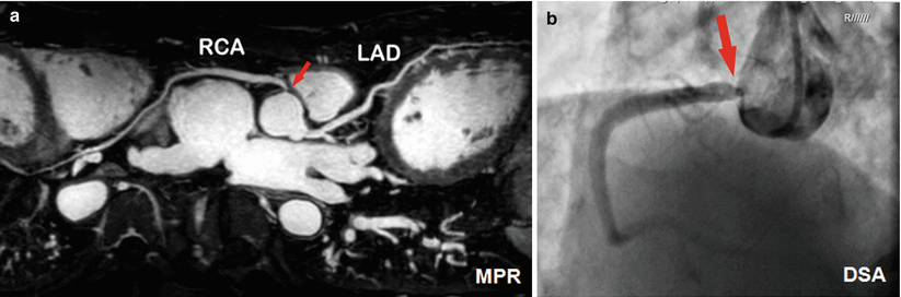


Fig. 6.4
Contrast enhanced coronary MRA at 3 T. A 65-year-old man with significant stenosis at the original of RCA (a) as shown in the coronary MR angiography (the MPR image); and (b) matched by digital subtraction angiography. The imaging time for the MR angiogram was 5 min (Courtesy of Dr. Qi Yang from Beijing Xuanwu Hospital. Reproduced with permission)
< div class='tao-gold-member'>
Only gold members can continue reading. Log In or Register to continue
Stay updated, free articles. Join our Telegram channel
Full access? Get Clinical Tree
