ms) is the Somatom Definition dual-source CT scanner [5] (Siemens Medical Solutions USA, Malvern, PA). Cardiac CT is a non-invasive clinical procedure to image the coronary arteries and was the first 4-dimensional CT (4D CT) application.
The first applications of 4D CT imaging of the lung tumor subject to the respiratory motion were first published by Vedam et al. [20] and Ford et al. [7] on the AcQSIM SSCT scanner (Philips Medical Systems, Andover, MA). The smallest pitch on this scanner was 0.5, which is defined as the table travel per rotation divided by the width of the x-ray beam on the rotation axis. A slow gantry rotation cycle of 1.5 s was used to slow down the table speed to meet the data sufficiency condition [17]. However, the table speed in this design was still too fast for 4D CT and resulted in gaps between images. Also the long acquisition time of up to 7 min due to the limited coverage of the SSCT scanner was not well suited to the clinical application of 4D CT.
The first clinical use of 4D CT was made by commercialization of the cine 4D CT (first announced at the AAPM 2002 Annual Meeting in Montreal, Canada) on the LightSpeed MSCT scanner (GE Healthcare, Waukesha, WI) [17]. The cine 4D CT utilized the cine CT scan capability already available on the LightSpeed CT scanner, which can scan at the same slice location for multiple gantry rotations. It does not require any hardware or software modification on the LightSpeed CT scanner, and it only needs an image sorting software, which correlates the same phase of CT images across the multiple table positions to a single phase of 4D CT images. The GE LightSpeed CT allows for a large coverage of cine CT scan up to over 30 cm in a single scan setup, convenient for the application of cine 4D CT. Radiation dose in the thorax application of 4D CT is generally less than 50 mGy. Low et al. [3] proposed a similar cine 4D CT technique on a Siemens Somatom 4-slice CT using a spirometer to record the respiratory signal. In their approach, each cine CT scan of 1 cm coverage requires a new scan setup [15, 16]. It takes 15 scans of 0.5 s (7.5 s total x-ray on time) per position to scan over one respiratory cycle of data. There was an inter-scan delay of 0.25 s between two 0.5 s scans. In total, 11.25 s per step was needed by taking into account the inter-scan delay time. A scanning pause of about 2 min after 7 scans was required for the user to reprogram another sequence of 7 scans. Although this approach could achieve 4D CT, it was not very practical for a large coverage of over 30 cm due to an inconvenience of setting up the scan protocol.
Fig. 2.1
Illustration of a helical CT scan with four active detector rows and its pitch definition
Both Phillips and Siemens later adopted a low-pitch helical CT scanning mode from cardiac CT for their 4D CT design [11]. This design was commercialized in 2006 on the MSCT scanners of at least 16 slices. In comparison, all the LightSpeed MSCT scanners of 4 slices and up, which have the cine CT scan capability that allows for a large coverage of the thorax in a simple protocol setup, were applicable for 4D CT. We will detail the data sufficiency condition governing the 4D CT data collection; present the design of the commercial helical 4D CTs from Philips and Siemens; compare the differences between the helical 4D CT and the cine 4D CT in data acquisition, slice thickness, acquisition time and work flow; review the respiratory monitoring devices in 4D CT; and understand the causes of image artifacts in 4D CT.
2.2 Helical 4D CT Data Acquisition
The challenge in 4D CT imaging is to capture a complete breathing cycle of the lung motion in CT imaging. Since no CT detector is able to cover the whole lungs, and the conventional scan speeds for diagnostic CT and cardiac CT imaging are still too fast for 4D CT of the lungs. Special care has to be taken to ensure the scanner parameters such as pitch value, gantry rotation speed, table speed or table translation per rotation, and detector configuration are suitable for 4D CT imaging. Figure 2.1 is an illustration of a helical CT system. An X-ray source sends out a cone-like radiation field illuminating a multi-row detector. It is characterized by the in-plane fan angle of about  and the x-ray collimation (the active detector width) at the center of rotation. Since the patient table is moving while the CT gantry is rotating, the illumination field follows a spiral course in a patient centric coordinate system. Table motion and gantry rotation speed have to be selected in a way that (i) each volume element in the lungs is covered in the X-ray cone-beam for at least a whole breathing cycle. In the following, the interplay between detector aperture, gantry rotation, table motion and breathing frequency is discussed in Sect. 2.2.1. Section 2.2.2 explains the influence of detector configuration settings, and Sect. 2.2.3 the correlation between scan settings and image resolution. The breathing phase selection and respective differences between cine and helical 4D CT is discussed in Sect. 2.4. Finally, an overview on commercial helical CT systems, and respiratory monitoring devices is given in Sects. 2.5 and 2.6, respectively.
and the x-ray collimation (the active detector width) at the center of rotation. Since the patient table is moving while the CT gantry is rotating, the illumination field follows a spiral course in a patient centric coordinate system. Table motion and gantry rotation speed have to be selected in a way that (i) each volume element in the lungs is covered in the X-ray cone-beam for at least a whole breathing cycle. In the following, the interplay between detector aperture, gantry rotation, table motion and breathing frequency is discussed in Sect. 2.2.1. Section 2.2.2 explains the influence of detector configuration settings, and Sect. 2.2.3 the correlation between scan settings and image resolution. The breathing phase selection and respective differences between cine and helical 4D CT is discussed in Sect. 2.4. Finally, an overview on commercial helical CT systems, and respiratory monitoring devices is given in Sects. 2.5 and 2.6, respectively.2.2.1 Data Sufficiency Condition (DSC)
To achieve 4D CT imaging of an object in the presence of respiratory motion, one must acquire data at each location for the duration of at least one breath cycle plus the duration needed to acquire sufficient projections for one image reconstruction. This is the data sufficiency condition (DSC) for 4D CT imaging [16]. The time needed to acquire one image is equal to one gantry rotation cycle for full-scan reconstruction (FSR) or  of a gantry rotation cycle plus fan-angle for half-scan reconstruction (HSR) [18], which is
  plus about
  , amounting to roughly
  gantry rotations. Additional data acquisition is needed because it takes at least
  of a gantry rotation cycle in CT for reconstruction of an image and to ensure that there are images at both ends of a complete breath cycle. This additional data acquisition is not necessary for projection x-ray imaging such as fluoroscopy in which each projection is an image by itself [13]. Two acquisition modes, helical and cine, can be used to realize the 4D CT imaging. A helical CT scan acquires data when the table translates at a constant speed programmed by a pitch factor
  , which is defined as the table travel per rotation divided by the width of the x-ray beam projected onto the rotation axis (Fig. 2.1).
of a gantry rotation cycle plus fan-angle for half-scan reconstruction (HSR) [18], which is plus about , amounting to roughly gantry rotations. Additional data acquisition is needed because it takes at least of a gantry rotation cycle in CT for reconstruction of an image and to ensure that there are images at both ends of a complete breath cycle. This additional data acquisition is not necessary for projection x-ray imaging such as fluoroscopy in which each projection is an image by itself [13]. Two acquisition modes, helical and cine, can be used to realize the 4D CT imaging. A helical CT scan acquires data when the table translates at a constant speed programmed by a pitch factor , which is defined as the table travel per rotation divided by the width of the x-ray beam projected onto the rotation axis (Fig. 2.1).To satisfy the DSC with FSR, the pitch values

and with HSR
where  and
and  are the durations of the gantry rotation cycle and the breath cycle, respectively. Let us examine the formula for FSR. If the breath cycle
  is the same as the
  , then after one
  (e.g.,
  s), the detector moves in and out of the x-ray beam in exactly one
  . Taking into account of the extra acquisition of
  for one image reconstruction,
  0.5. If the breath cycle
  is 4 times of
  (i.e.,
  s,
s,  s), then
  . Typically
  s and
s and  s and
s and  , almost the same gantry rotation cycle as the typical pitch factor of 0.1 or less in the helical 4D CT in Tables 2.1 and 2.2. Similar reasoning can be applied to Eq. (2.2) for HSR.
(2.1)
(2.2)
and are the durations of the gantry rotation cycle and the breath cycle, respectively. Let us examine the formula for FSR. If the breath cycle is the same as the , then after one (e.g., s), the detector moves in and out of the x-ray beam in exactly one . Taking into account of the extra acquisition of for one image reconstruction, 0.5. If the breath cycle is 4 times of (i.e., s, s), then . Typically s and s and , almost the same gantry rotation cycle as the typical pitch factor of 0.1 or less in the helical 4D CT in Tables 2.1 and 2.2. Similar reasoning can be applied to Eq. (2.2) for HSR.Fig. 2.2
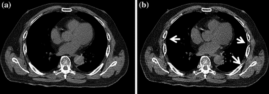
Images reconstructed with the full scan reconstruction (FSR) with  of CT data in (a) and the half scan reconstruction (HSR) with
  of CT data in (b). The arrows indicate artifacts coming out of HSR. The image of FSR is also less noisy than the image of HSR because FSR has more projection data in the image reconstruction than HSR
of CT data in (a) and the half scan reconstruction (HSR) with of CT data in (b). The arrows indicate artifacts coming out of HSR. The image of FSR is also less noisy than the image of HSR because FSR has more projection data in the image reconstruction than HSRAlthough HSR is used in cardiac CT for better temporal resolution, FSR is typically used in 4D CT because FSR gives rise to fewer image artifacts between 25 and 50 cm reconstruction field of view (FOV) than HSR (Fig. 2.2). The FOV with HSR is typically less than 25 cm only to cover the heart. The FOV for radiation therapy simulation is at least 50 cm. Since FSR uses more data in the image reconstruction than HSR, its image will also be less noisy. One very important observation of the pitch value selection is that the longer the breath cycle  or the shorter the gantry rotation cycle
  is, the smaller the pitch factor
  becomes. In diagnostic CT imaging with patient breath-hold and without gating,
  is about 1, which is 10 times faster than in a helical 4D CT scan with respiratory gating!
or the shorter the gantry rotation cycle is, the smaller the pitch factor becomes. In diagnostic CT imaging with patient breath-hold and without gating, is about 1, which is 10 times faster than in a helical 4D CT scan with respiratory gating!2.2.2 Data Acquisition Modes
A MSCT can be characterized by the number of data channels that can be simultaneously read-out (SRO) in the patient table direction. This number of SRO is also frequently referred to as the number of slices in MSCT. A MSCT with a higher number of SRO typically means a newer MSCT that can scan the same coverage faster. To acquire the cine 4D CT data with GE scanners, the numbers of SRO data channels are 4, 8, 16 and 64 (Fig. 2.3a). To acquire the helical 4D CT data with Siemens or Philips scanners, the numbers of SRO data channels are 16, 20, 40, and 64 (Fig. 2.3c). The reason that helical 4D CT started at 16-slice was because Siemens/Philips only introduced the low pitch helical CT scan ( ) in their 16-slice and up CT scanners. This practice is typical in commercial CT that a new feature is only introduced in newer CT scanners, which was 16-slice at the time.
) in their 16-slice and up CT scanners. This practice is typical in commercial CT that a new feature is only introduced in newer CT scanners, which was 16-slice at the time.Fig. 2.3
(a) GE detector layout for 4, 8, 16 and 64 data channels. The shaded regions illustrate the data channels that can be simultaneously read-out. (b) Data acquisition layout of GE 4D CT for various numbers of data channels. Each 2.5 mm datum is combined from two to four data channels of 1.25 or 0.625 mm. The speed of cine 4D CT acquisitions is the same for both 8 and 16 data channels, which utilizes 2 cm ( mm) detector coverage. (c) Siemens/Philips detector layout of 16, 20, 40, and 64 data channels. Siemens 40 and 64-channel scanners (marked with asterisk *) based on the 20 and 32-channel detectors, respectively, utilize the technology of z-flying focal spot to fast switch between two focal spots at each projection angle to achieve the effect of 40 and 64 data channels, respectively. Note that the physical detector sizes of 40 and 64-channel are 2.4 and 2.88 cm, respectively. Philips 64-channel has the detector size of 4 cm, identical to GE 64-channel. (d) Data acquisition layout of Siemens/Philips helical 4D CT for various data channels. The detector coverage of 4 cm is the same for the Philips 40 and 64 channels. The detector coverage of 2.4 cm is the same for the Siemens 16, 20 and 40 channels
mm) detector coverage. (c) Siemens/Philips detector layout of 16, 20, 40, and 64 data channels. Siemens 40 and 64-channel scanners (marked with asterisk *) based on the 20 and 32-channel detectors, respectively, utilize the technology of z-flying focal spot to fast switch between two focal spots at each projection angle to achieve the effect of 40 and 64 data channels, respectively. Note that the physical detector sizes of 40 and 64-channel are 2.4 and 2.88 cm, respectively. Philips 64-channel has the detector size of 4 cm, identical to GE 64-channel. (d) Data acquisition layout of Siemens/Philips helical 4D CT for various data channels. The detector coverage of 4 cm is the same for the Philips 40 and 64 channels. The detector coverage of 2.4 cm is the same for the Siemens 16, 20 and 40 channelsThe number of physical data channels on a MSCT is at least the number of data channels of SRO. Both GE’s 4 and 8 channels have 16 physical detectors. For GE’s 16 and 64 channels, there are 24 and 64, detectors, respectively. During data acquisition, the cine 4D CT utilizes the data acquisition modes of  ,
,  ,
,  and
and  mm on GE’s 4, 8, 16 and 64-slice CTs, respectively (Fig. 2.3b) to produce the images of slice thickness 2.5 mm for treatment planning. Combination of smaller data channels to 2.5 mm slice is conducted in data acquisition. A 16-slice CT may not have a significant advantage over an 8-slice CT in terms of acquisition speed for the cine 4D CT because the detector size is at the maximum of 2 cm for both the 8- and 16-slice GE CT.
, , and mm on GE’s 4, 8, 16 and 64-slice CTs, respectively (Fig. 2.3b) to produce the images of slice thickness 2.5 mm for treatment planning. Combination of smaller data channels to 2.5 mm slice is conducted in data acquisition. A 16-slice CT may not have a significant advantage over an 8-slice CT in terms of acquisition speed for the cine 4D CT because the detector size is at the maximum of 2 cm for both the 8- and 16-slice GE CT.In helical 4D CT data acquisition, the raw data before helical data interpolation are smaller than 1.5 mm (Fig. 2.3d). For the 16-slice, the mode of data acquisition is  mm. For the Siemens 20/40-slice, it is
  mm. For the Philips 40/64-slice, it is
  mm. Siemens 16, 20 and 40-slice CTs have the same detector coverage of 2.4 cm. Therefore, the speed of helical 4D CT is the same for the Siemens 16, 20 and 40-slice CTs. The Siemens 40 and 64-slice scanners use the z flying-focal spot to fast-switch the focal spot between two positions to double-sample each angle of projection data to achieve the effect of 40 and 64-slice data even though their detector channels are 20 and 32, respectively [6]. The detector size of 16, 20 and 40-slice Siemens CTs is 2.4 cm, and it is 2.88 cm for the 64-slice Siemens CT. The Philips 40 and 64-slice CTs have 4 cm detector coverage, and their data acquisition is at
  mm for the helical 4D CT, which will shorten the acquisition time for their large coverage. It is important to note that slice broadening of 180 % in the low-pitch helical 4D CT prevents the smallest data element in data acquisition to be greater than 1.5 mm.
mm. For the Siemens 20/40-slice, it is mm. For the Philips 40/64-slice, it is mm. Siemens 16, 20 and 40-slice CTs have the same detector coverage of 2.4 cm. Therefore, the speed of helical 4D CT is the same for the Siemens 16, 20 and 40-slice CTs. The Siemens 40 and 64-slice scanners use the z flying-focal spot to fast-switch the focal spot between two positions to double-sample each angle of projection data to achieve the effect of 40 and 64-slice data even though their detector channels are 20 and 32, respectively [6]. The detector size of 16, 20 and 40-slice Siemens CTs is 2.4 cm, and it is 2.88 cm for the 64-slice Siemens CT. The Philips 40 and 64-slice CTs have 4 cm detector coverage, and their data acquisition is at mm for the helical 4D CT, which will shorten the acquisition time for their large coverage. It is important to note that slice broadening of 180 % in the low-pitch helical 4D CT prevents the smallest data element in data acquisition to be greater than 1.5 mm.2.2.3 Image Location, Slice Thickness, and Scan Time
Helical 4D CT scan data allow for CT image reconstruction at any location by permitting data interpolation between two neighboring detector elements (Fig. 2.4), whereas cine 4D CT scan data allow for reconstructions only at the scan position. When using 4D CT to scan patients with lung cancer, it is important to have a complete coverage of the lungs for tumor delineation and dose calculation. The flexibility of image reconstruction at any location is not important as long as the images of uniformly spaced slices can be reconstructed to create a 4D volume. Typical image slice thicknesses in radiation treatment planning are 2–3 mm. There is a penalty from data interpolation in helical 4D CT as it widens the slice sensitivity profile, a measure of the slice thickness of the CT image. It is important to use thin slice collimation of  mm in helical 4D CT on a 16-slice MSCT scanner because data interpolation will widen the slice thickness to almost 2.7 mm (that is, the 1.5 mm slice will be thickened to 1.8 times its original width). Similarly, this means that if the detector configuration is
  mm, the slice thickness will become 4.5 mm in helical 4D CT. Same
  mm collimation in cine 4D CT will generate the slices of 2.5 mm because no data interpolation is in the cine CT image reconstruction. In diagnostic imaging, data interpolation causes only about 20 % widening when the pitch is greater than 0.5; the amount of widening reaches 180 % when the pitch is less than 0.2 (Fig. 2.5). To better understand this, we can take two independent slices of 2.5 mm at two neighboring locations in cine 4D CT and interpolate for an image located equidistant to the two slices; in such a case, interpolation would assign 50 % weight to each image, and the composite image will become a 5.0 mm slice (resulting in 200 % broadening of the slice thickness). Image reconstruction at pitch values of less than 0.1 in helical 4D CT significantly thickens the CT images as shown in Fig. 2.4. Once the pitch factor
  becomes 0, helical CT interpolation is no longer needed and the helical 4D CT becomes cine 4D CT. That is the reason that the typical detector configuration in a 16-slice MSCT is
  mm to keep the slice thickness
  mm.
mm.
 < div class='tao-gold-member'>


mm in helical 4D CT on a 16-slice MSCT scanner because data interpolation will widen the slice thickness to almost 2.7 mm (that is, the 1.5 mm slice will be thickened to 1.8 times its original width). Similarly, this means that if the detector configuration is mm, the slice thickness will become 4.5 mm in helical 4D CT. Same mm collimation in cine 4D CT will generate the slices of 2.5 mm because no data interpolation is in the cine CT image reconstruction. In diagnostic imaging, data interpolation causes only about 20 % widening when the pitch is greater than 0.5; the amount of widening reaches 180 % when the pitch is less than 0.2 (Fig. 2.5). To better understand this, we can take two independent slices of 2.5 mm at two neighboring locations in cine 4D CT and interpolate for an image located equidistant to the two slices; in such a case, interpolation would assign 50 % weight to each image, and the composite image will become a 5.0 mm slice (resulting in 200 % broadening of the slice thickness). Image reconstruction at pitch values of less than 0.1 in helical 4D CT significantly thickens the CT images as shown in Fig. 2.4. Once the pitch factor becomes 0, helical CT interpolation is no longer needed and the helical 4D CT becomes cine 4D CT. That is the reason that the typical detector configuration in a 16-slice MSCT is mm to keep the slice thickness mm.Only gold members can continue reading. Log In or Register to continue
Stay updated, free articles. Join our Telegram channel
Full access? Get Clinical Tree
