Fig. 13.1
Patent ductus arteriosus. Graphic depiction of patent ductus arteriosus (PDA) as visualized from a left anterior oblique view. The typical ductus extends as illustrated from the junction of the main pulmonary artery (PA) with the left pulmonary artery (LPA) to the descending thoracic aorta just distal to the left subclavian artery (LSA). AO aorta, IA innominate artery, LCCA left common carotid artery (Reproduced with permission from Hillman et al. [130])
In most patients with a left aortic arch, the ductus arteriosus is a left-sided structure. A right or left-sided ductus may be present in patients with a right aortic arch. In some cases, the ductus arteriosus originates from the innominate or subclavian arteries or may even be duplicated (bilateral ductus). Two important issues merit mention: (1) anatomic factors such as aortic arch sidedness, aortic arch branching pattern, and ductal origin/position may result in anomalies causing a vascular ring [1] and (2) an abnormal location, course or shape of the ductus arteriosus, as well as bilateral ductus, are more likely to occur in the setting of complex CHD.
In the normal fetal circulation, the right ventricle generates approximately two-thirds of the fetal cardiac output. The majority of this blood is ejected into the descending aorta through the ductus arteriosus, as only a small fraction of the right ventricular output (5–10 %) passes through the lungs. Thus, this communication is an essential component of normal fetal life, allowing for right ventricular ejection into the descending aorta within the context of a high-resistance pulmonary circulation.
In the normal full-term infant, functional closure of the ductus arteriosus occurs several hours after birth. Anatomic closure of this channel takes place in the first few weeks of life. Failure of the ductus arteriosus to close, a process not completely understood, results in persistent ductal patency (patent ductus arteriosus or PDA). As an isolated lesion, it accounts for between 4 and 12 % of all cases of CHD.
Associated Defects
A PDA can be found in isolation or in association with other cardiovascular anomalies (e.g., atrial septal defect, ventricular septal defect, atrioventricular septal defect, coarctation of the aorta). A high incidence is found in premature neonates, infants with respiratory distress syndrome, patients affected by rubella syndrome, and children living at high altitudes. Ductal-dependency for either pulmonary or systemic blood flow may be part of the physiology of moderate to severe forms of CHD. The discussion that follows focuses primarily on the PDA as an isolated lesion. The presence and role of the PDA in association with other cardiac defects is also briefly addressed.
Pathophysiology
In the isolated PDA, shunt magnitude is determined by the physical size of the communication (length and internal diameter) and the relationship between the systemic and pulmonary vascular resistances. A small PDA may have little to no physiologic impact. However, the hemodynamic effects of moderate-to-large communications are those of a classic left-to-right shunt manifested by increased pulmonary blood flow, resulting in left atrial and left ventricular volume overload. In a moderate size PDA, an element of ductal constriction is present, so shunting is restrictive to some extent and the pulmonary artery pressure is mildly elevated or may even be normal. Large communications are associated with a greater degree of pulmonary artery pressure elevation. In this setting, shunting can be bidirectional and dictated primarily by the resistances of the vascular beds at either sides of the PDA. The increased left atrial pressure associated with large shunts may lead to stretching of the foramen ovale and result in an additional shunt at this level, further compounding the volume load presented to the pulmonary arteries.
Management Considerations
The management options in the infant beyond prematurity or in the older child who requires ductal closure are occlusion of the communication in the cardiac catheterization laboratory or surgical closure. Various approaches have been used for surgical closure of the isolated PDA, including closed procedures via thoracoscopy (either robotically or video assisted) and open interventions, in most cases, via a thoracotomy. The adult or older patient with a PDA presents a challenge as friable tissue, aneurysmal dilation, or ductal calcification increases the likelihood of procedural complications.
Applications of Transesophageal Echocardiography
TEE has been used for diagnostic applications in the detection and characterization of flow across a PDA [2–8]. However, the use of TEE for this sole purpose is relatively rare. As previously noted, a ductus or ligamentum arteriosum may be part of a vascular ring. In these cases transesophageal instrumentation is generally avoided as probe placement or manipulation can lead to airway compromise due to compression of the trachea by surrounding vascular structures.
In the current era, transcatheter interventions aimed at ductal occlusion are guided primarily by fluoroscopy and angiography. Although TEE has been used in this setting [8, 9], and more recently, three-dimensional (3D) TEE has also been applied [10, 11], its role in these procedures is limited. The use of TEE has also been documented during interventions involving thoracoscopic surgery for the PDA, as well as open procedures in both children and adults [12–16]. The primary role is that of evaluation of shunt flow and magnitude, as well as the success of surgery in obliterating the communication. Currently, TEE is not considered an indication solely for monitoring or assessing the results of surgical closure of an isolated PDA. As such, the discussion that follows is relevant mostly to the use of TEE in the evaluation of patients undergoing surgical ligation or division of a PDA in the setting in which additional cardiac defects are also being addressed.
Goals of TEE Prior to Catheter or Surgical Intervention
Visualization of a PDA and Detection of Ductal Shunting
Direct imaging of the ductus arteriosus to assess patency can be challenging by two-dimensional (2D) transesophageal imaging alone. The examination of a PDA relies to a significant extent on the use of Doppler ultrasound techniques that interrogate flow across the pulmonary artery and descending aorta. The upper esophageal views, particularly the upper esophageal pulmonary artery long axis (UE PA LAX) and the upper esophageal aortic arch short axis (UE Ao Arch SAX), are essential for this evaluation (Fig. 13.2, Video 13.1). These views allow direct visualization of the ductal communication between the aorta and pulmonary artery. In addition, the mid esophageal ascending aortic short axis (ME Asc Ao SAX) with probe anteflexion and counterclockwise rotation, and the mid esophageal right ventricular inflow-outflow (ME RV In-Out) views (Fig. 13.3, Video 13.2), can also provide evidence of left-to-right ductal shunting into the pulmonary artery. As described below, views of the descending aorta that allow for the characterization of flow are also helpful. The combination of these different TEE views for the typical left-sided PDA enables visualization of the communication, including detection of ductal shunting, determination of shunt direction, and gross estimation of shunt magnitude.
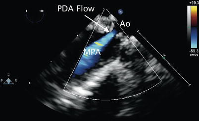
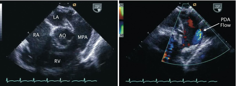
Fig. 13.2
Patent ductus arteriosus. Upper esophageal pulmonary artery long axis view demonstrating flow by color Doppler (blue signal away from imaging probe) corresponding to left-to-right shunting across a patent ductus arteriosus (PDA flow). Ao aorta, MPA main pulmonary artery
Fig. 13.3
Patent ductus arteriosus. Left panel, two-dimensional image of mid esophageal right ventricular inflow-outflow view. Right panel, corresponding color Doppler image depicts flow (blue signal) from patent ductus arteriosus (PDA) into main pulmonary artery (MPA). AO aorta, LA left atrium, RA right atrium, RV right ventricle
Characterization of Flow Across a PDA
In the setting of a restrictive ductus arteriosus and relatively normal pulmonary artery pressures, the higher systemic arterial pressure results in continuous left-to-right shunting into the pulmonary artery throughout the cardiac cycle. This communication can be demonstrated by spectral Doppler assessment and color flow mapping in the upper esophageal, ME Asc Ao SAX, and ME RV In-Out views as previously described. Sampling near the pulmonary end in this case displays continuous high velocity flow, peaking in late systole directed away from the transducer. Color flow Doppler mapping increases the sensitivity of the interrogation and demonstrates turbulent or aliased flow (seen as a mosaic color pattern) from the PDA into the distal main pulmonary artery (Fig. 13.4, Video 13.3). The ductal flow can extend to the level of the pulmonary valve, or beyond into the right ventricular outflow tract, in the presence of pulmonary regurgitation.
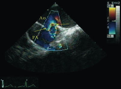
Fig. 13.4
Patent ductus arteriosus. Upper esophageal aortic arch short axis view with color mapping demonstrating aliased flow from the aorta (Ao) into the pulmonary artery (PA) across a patent ductus arteriosus (arrows) (Reproduced with permission from Russell et al. [131])
In the setting of pulmonary hypertension, shunting across the ductus is continuous and of low velocity, peaking in late systole [17, 18]. As the pulmonary artery pressure and pulmonary vascular resistance increase, there will be blunting of the left-to-right shunt in diastole, so that systolic left-to-right shunting predominates. Further increases in pulmonary artery pressure/vascular resistance result in low velocity bidirectional ductal shunting (right-to-left during systole and left-to-right in late systole extending into late diastole) [19]. This flow pattern can also be seen in ductal-dependent left-sided obstructive lesions such as hypoplastic left heart syndrome or interrupted aortic arch (see below) and can also be a normal finding in the neonate [20]. Increasing levels of pulmonary artery pressures and the development of increased pulmonary vascular resistance are characterized by blunting of the left-to-right shunt in diastole. In some cases, exclusive right-to-left ductal shunting is present (reverse ductal shunting), peaking in early systole; this pattern is generally seen with significant elevation in pulmonary artery pressure/vascular resistance (such as obstructed total anomalous pulmonary venous return), and in many cases can be difficult to detect by TEE. Injection of agitated saline into a peripheral or central venous catheter while imaging the descending aorta may demonstrate microcavitations distal to the level of the left subclavian artery, consistent with ductal level right-to left shunting. [6]
Doppler Interrogation of Descending Aorta
The presence of a PDA in association with a large amount of shunt flow may also be suggested by an increase in the caliber of the descending aortic pulsations. Spectral Doppler analysis in the descending aorta demonstrates both antegrade systolic flow and diastolic flow reversal. They are best appreciated in the descending aortic short (Desc Ao SAX, Fig. 13.5) and long axis (Desc Ao LAX, Fig. 13.6) views, in the areas distal to the ductus arteriosus. The retrograde flow represents diastolic runoff into the pulmonary circulation within the context of low pulmonary artery diastolic pressures (Figs. 13.7 and 13.8). The presence and magnitude of holodiastolic flow reversal in the distal descending aorta also provide clues regarding the extent of ductal shunting, as increasing degrees of retrograde flow are present with larger shunts. A parameter that has been examined by transthoracic imaging to estimate shunt size is the ratio of the areas corresponding to retrograde and forward flows [21]. Although not yet validated for TEE, this may also provide a crude index of shunt magnitude.
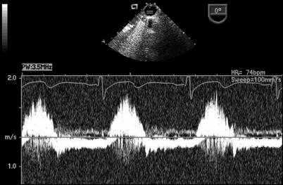
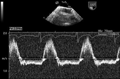
Fig. 13.5
Descending aorta. Graphic illustration of imaging probe position and cross-section displayed in the mid esophageal descending aortic short axis view. Ao ascending aorta, DsAo descending aorta (Reproduced with permission from Cahalan [132])
Fig. 13.6
Descending aorta. Graphic illustration of imaging probe position and cross-section displayed in the mid esophageal descending aortic long axis view. Ao ascending aorta, DsAo descending aorta (Reproduced with permission from Cahalan [132])
Fig. 13.7
Patent ductus arteriosus. Spectral Doppler interrogation in the mid esophageal descending aortic short axis view demonstrating systolic forward flow as well flow reversal that continues throughout diastole in a patient with a patent ductus arteriosus
Fig. 13.8
Patent ductus arteriosus. Spectral Doppler tracing obtained by rotating the imaging plane to an orthogonal orientation (mid esophageal descending aorta long axis view) with respect to same patient and probe position as shown in Fig. 13.7. This view provides a more suitable angle for Doppler interrogation and likewise demonstrates holodiastolic flow reversal in the distal descending aorta in association with a patent ductus arteriosus
Estimation of Pulmonary Artery Systolic Pressure from the PDA Jet
The use of Doppler ultrasound facilitates the assessment of systolic pressure gradients between the systemic and pulmonary circulations and estimation of the pulmonary artery systolic pressure (PASP) [22, 23]. This can be accomplished by examining the velocity from the left-to-right jet across the ductus as follows [24]:
 V, represents the peak flow velocity (in meters per second) across the ductus in late systole; SBP, systolic blood pressure
Several limitations have been described in the assessment of PASP using this approach [23]. Although they have been reported for transthoracic imaging, these issues are also relevant to TEE. These limitations include potential errors related to position of the spectral sample volume, possible contamination of the continuous wave Doppler signal by flow from adjacent structures, and a PDA shape that does not allow for optimal Doppler cursor alignment for determination of maximal flow velocity, resulting in underestimation of the true pressure drop across the communication. This last issue may be more significant during TEE imaging, as movement of the probe is confined within the esophagus/stomach, in contrast to one’s ability to move a transthoracic probe freely across multiple windows to optimize the Doppler evaluation.
Estimation of PASP from the Tricuspid Regurgitant Jet Velocity
Right ventricular systolic pressure (RVSP) also can be estimated from the peak velocity of a tricuspid regurgitant jet, if present (Fig. 13.9, Video 13.4), using the following equation:
 V, represents the peak flow velocity of the tricuspid regurgitant jet (in meters/second); RAp, mean right atrial pressure [25].
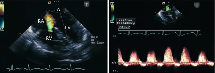
Fig. 13.9
Tricuspid regurgitation. Mid esophageal four chamber view illustrating the jet of tricuspid regurgitation displayed by color flow imaging (left panel) and the corresponding spectral Doppler tracing (right panel). Note that the peak velocity of the regurgitant jet reaches nearly 4 m/s. The peak velocity predicts an elevated right ventricular and pulmonary artery pressure in this infant. LA left atrium, LV left ventricle, RA right atrium, RV right ventricle
In the absence of right ventricular outflow tract obstruction, RVSP equals PASP.
Evaluation of Left Atrial and Left Ventricular Size for Dilation
In the absence of co-existing structural defects, the size of the main pulmonary artery, left atrium, and left ventricle may correlate with the degree of the ductal shunting (Fig. 13.10, Video 13.5).
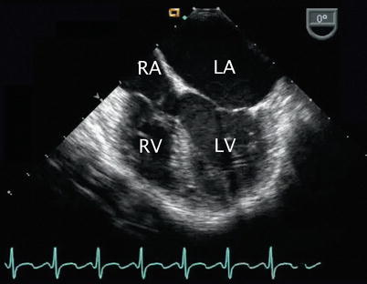
Fig. 13.10
Left heart dilation resulting from a patent ductus arteriosus. Image depicts a mid esophageal four chamber view in a patient with a volume-loaded left heart corresponding to left-to-right ductal level shunting as manifested by dilation of left-sided structures, particularly the left atrium in this case. A tricuspid valve aneurysm is seen. LA left atrium, LV left ventricle, RA right atrium, RV right ventricle
Additional Applications
The assessment of associated cardiovascular defects (e.g., atrioventricular septal defect, subaortic stenosis) represents the main indication for the use of intraoperative TEE in patients with a PDA. The approach suggested in Chap. 4 for the structural evaluation of the heart by TEE should be followed. Depending upon the nature of the associated defects, suitable TEE planes should be obtained to assess the details of the anatomy. Aspects to be examined as part of a comprehensive examination include (but are not limited to) interrogation of atrioventricular and semilunar valves, outflow tracts, and assessment of ventricular systolic function. However even when evaluation of other defects is the primary objective, the mid and upper esophageal TEE views (as noted above) should still be obtained to evaluate the PDA. Of note, it is good practice to utilize these views on a regular basis whenever a comprehensive study is performed; occasionally one can discover a PDA that had previously been unsuspected.
Goals of TEE After Catheter or Surgical Intervention
Detection of Residual Ductal Shunting
The magnitude of residual ductal shunting during transcatheter closure or surgery is likely to be relatively small, if at all present. Under these circumstances, a signal representing high velocity, disturbed flow with shunting in the left-to-right direction may be detected in the distal aspect of the main pulmonary artery, near the origin of the left pulmonary artery (in the presence of a left aortic arch).
Additional Applications
Depending on the nature of associated cardiovascular lesions and the catheter-based or surgical intervention(s) performed, TEE should be applied to the post procedure evaluation, as pertinent for the pathology as discussed throughout this textbook.
Aortopulmonary Window
Anatomic Features
Aortopulmonary (AP) window, also referred to as aortopulmonary septal defect, aortopulmonary fenestration, and aorticopulmonary window/septal defect, is a malformation characterized by a defect in the wall between the ascending aorta and the pulmonary artery, creating a communication between these structures [26]. It is thought to be the result of abnormal development of the AP septum. Anatomically and physiologically, an AP window can resemble a truncus arteriosus; however unlike, truncus arteriosus, two distinct semilunar valves are present. It represents a rare defect, accounting for 0.1 % of all congenital cardiovascular anomalies.
The size and location of the communication can vary related to the extent of faulty partitioning of the AP septum. Mori and colleagues classified the AP window into three types (Fig. 13.11) [27]:
Fig. 13.11
Aortopulmonary window. Classification of aortopulmonary window as per Mori et al. (refer to text) (Reproduced with permission from Gaynor [133])
Type I: found in the proximal aspect of the AP septum, located just above the sinuses of Valsalva; it represents the most common type of the defect (referred to as proximal defect)
Type II: found in the most distal part of the AP septum or most superior aspect of the ascending aorta, adjacent to the right pulmonary artery (referred to as distal defect)
Type III: a combination of Types 1 and II, involving the majority of the ascending aorta (referred to as total defect)
In a large review of cases, Kutsche and Van Mierop suggested that different developmental mechanisms likely account for the distinct forms of the defect [28]. Their analysis described three morphologic types as follows:
A defect of small to moderate size with a more or less circular border located at the midpoint between the semilunar valves and pulmonary artery bifurcation
A similarly located defect in which the border represents a helix
A usually large defect without posterior (distal) border
Associated Defects
An AP window may occur in isolation, but more than half of the cases are associated with other cardiovascular malformations. Coexistent anomalies include PDA, septal defects at the atrial and/or ventricular levels, tetralogy of Fallot, double outlet right ventricle, type A interrupted aortic arch [31], right aortic arch, anomalous origin of the left coronary artery from the pulmonary artery [32], and coarctation of the aorta.
Pathophysiology
The magnitude of the shunt across an AP window relates to factors such as the size of the defect, pulmonary artery pressures, and relative resistances of the pulmonary and systemic circulations. Left-to-right shunting across the communication results in increased pulmonary blood flow, pulmonary hypertension, left-sided volume overload, and congestive symptoms. This condition is similar to the hemodynamic consequences of any other large abnormal vascular connection such as a PDA. An uncorrected communication can lead to the development of pulmonary vascular disease relatively early in life.
Management Considerations
Although successful transcatheter closure of an AP window has been reported [33–36], the standard treatment for this congenital lesion is considered to be surgical. The approach to this defect has evolved considerably over the years. In the past, simple ligation or division by suture closure was advocated [29, 37]; however, most centers now perform patch closure of the communication, using a median sternotomy and cardiopulmonary bypass (Fig. 13.12) [38, 39].
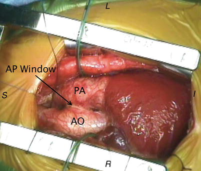
Fig. 13.12
Aortopulmonary window. Intraoperative photograph depicting the anatomical findings of an aortopulmonary (AP) window from a surgical perspective. AO aorta, PA pulmonary artery. Image orientation: I inferior, L left, R right, S superior
Applications of Transesophageal Echocardiography
As in many structural defects, the diagnosis of an AP window in the majority of cases is established by TTE alone [40–45]. Recently, the utility of 3D echocardiography has also been reported in the assessment of this anomaly [46]. Rarely, additional imaging studies are required to further characterize the defect. TEE has been shown to be of benefit in the perioperative management of patients with AP communications such as an AP window [47].
Goals of TEE Prior to Surgical Intervention
Identification of an AP Window
The AP window is displayed by 2D imaging as a direct communication between the arterial trunks. It appears as a deficiency or absence (echocardiographic “dropout”) of the wall normally interposed between the great arteries. The communication is usually large and frequently located along the anterior and leftward aspect of the aorta in the region where the great arteries are normally in apposition. The location and size of the defect, as well as its proximity to the semilunar valves are best evaluated in multiple views. Suggested TEE cross-sections to characterize an AP window are the UE PA LAX, UE Ao Arch SAX, and ME Asc Ao SAX views (Fig. 13.13 left panel, Video 13.6). The region of interest is the area of overlap between the great arteries or where they are seen in close proximity. The comprehensive evaluation of this defect may require the use of additional or non-standard TEE imaging planes, as may also be the case with other defects discussed throughout this textbook. For example, from the mid esophageal aortic valve long axis (ME AV LAX), mid esophageal long axis (ME LAX), mid esophageal ascending aortic long axis (ME Asc Ao LAX), and their respective modified views, the probe can be withdrawn slowly and sweeps performed by rotating the transducer in clockwise and counterclockwise fashions to display the great arteries and the communication (Fig. 13.14, Video 13.7). The deep transgastric long axis (DTG LAX) and sagittal (DTG Sagittal) views, as well as modified respective views that display the great arteries as they cross each other, provide complementary information. It is important to note that an AP window would represent an extremely rare new finding on TEE; therefore, when a presumptive AP window has been identified for the first time on a TEE study, it is important to exclude potential diagnostic pitfalls that can mimic this defect, such as false echocardiographic dropouts in this region. Confirmatory information should be obtained, as discussed below.

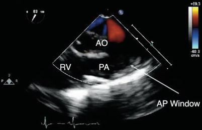
Fig. 13.13
Aortopulmonary window. Mid esophageal ascending aorta short axis view in infant with an aortopulmonary window. Note the echocardiographic drop out in the region between the arterial roots (arrow) corresponding to faulty aortopulmonary septation (left panel) and shunting across this region by color Doppler (right panel). Ao aorta, PA pulmonary artery
Fig. 13.14
Aortopulmonary window. View of the ascending aorta obtained at the upper esophageal level depicting an aortopulmonary (AP) window (arrow). AO aorta, PA pulmonary artery, RV right ventricle
Characterization of Shunting Across AP Window
Color Doppler plays a very important role in the echocardiographic evaluation of an AP window. It verifies and characterizes the flow across the communication, providing qualitative information regarding shunt direction and magnitude. The same TEE views described in the identification of the defect can be used for this evaluation (Fig. 13.13 right panel, Videos 13.6 and 13.7). The spectral Doppler examination demonstrates antegrade continuous forward flow into the pulmonary artery near the area of the defect (Fig. 13.15). The presence of pulmonary hypertension at or near systemic levels is the norm for most large defects. In this case, low velocity, laminar, bidirectional (predominantly left-to-right) shunting across the communication reflects the negligible systolic pressure gradient between the systemic and pulmonary beds. This condition may render the identification of shunting somewhat difficult. Adjustment of the Nyquist limit for the color Doppler scale enhances the detection of low velocity flows and can be used to facilitate the detection of shunting across the communication. It is important to distinguish the low velocity color flow signal across an AP window from the “bleeding” of color flow sometimes seen across the walls of the aorta and pulmonary artery in a normal heart. Interrogation of the ascending aorta near the communication or of the descending thoracic aorta may display diastolic flow reversal in the presence of low pulmonary vascular resistance. It is similar to the nature of descending aortic flow in a moderate to large-sized PDA, and serves as indirect evidence of the presence of an AP communication, although it is not specific of the type. Smaller, restrictive defects can display a turbulent color flow Doppler pattern that corresponds to high velocity, continuous left-to-right shunting across the area.
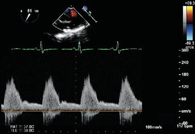
Fig. 13.15
Aortopulmonary window. Spectral Doppler tracing obtained in the same patient and same view as shown in Fig. 13.14. Note the systolic flow and continuous forward flow during diastole into the pulmonary artery
Estimation of Pulmonary Artery Systolic Pressure
As indicated, flow across large communications displays low velocity consistent with elevated pulmonary artery pressures. Smaller defects result in pressure restriction, displaying flow aliasing (mosaic pattern) by color Doppler and high velocity flow by spectral Doppler. The peak velocity of the continuous wave Doppler signal can be used to estimate PASP (as described for a PDA). The peak velocity of the tricuspid regurgitant jet, if present, can also be applied to estimate RVSP, as noted previously. Additional findings that may provide insight into the extent of pulmonary artery pressure elevation include: motion and configuration of the interventricular septum, right ventricular wall thickness, and degree of right ventricular dilation.
Additional Applications
Depending on the presence of associated defects, additional aspects of the anatomy should be examined using corresponding TEE views as necessary. The hemodynamic effects of the volume load result in dilation of the pulmonary arteries and left-sided cardiac structures. The nature of the runoff associated with an AP window may result in low systemic diastolic pressures, low coronary perfusion pressures, and the potential for coronary ischemia and/or myocardial dysfunction. Thus, it is essential to assess both global and segmental left ventricular systolic function in the preoperative evaluation. This assessment is best performed in the transgastric mid short axis (TG Mid SAX), transgastric basal short axis (TG Basal SAX), transgastric two chamber (TG 2 Ch), mid esophageal four chamber (ME 4 Ch), mid esophageal two chamber (ME 2 Ch), and ME LAX views (also refer to Chap. 5).
Intraoperative Monitoring
In rare cases, depending upon the location of the AP window and other factors such as the size and length of the communication, consideration may be given to using a surgical approach that obliterates the communication without the need for cardiopulmonary bypass. In this setting, TEE is valuable for intraoperative monitoring and assessing the results of surgery. In addition, TEE is extremely useful for evaluating global and segmental ventricular function as well as left ventricular preload, and also for excluding the presence of intracardiac/intravascular air.
Goals of TEE After Surgical Intervention
Assessment of the Repair
Obliteration of the abnormal AP connection in most cases requires patch closure (Fig. 13.16, Video 13.8). The post-repair TEE assessment should explore potential residual shunting and patency of the arterial roots to exclude obstruction of either the aorta or pulmonary artery. This represents the primary reason for morbidity in this lesion [48]. Semilunar valve competence also should be examined, as regurgitation can result from the repair, particularly if the AP window is proximally located near the semilunar valves.
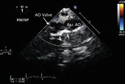
Fig. 13.16
Aortopulmonary window. Postoperative transesophageal echocardiogram in the mid esophageal ascending aortic long axis view depicts the bright region along the wall of the ascending aorta (Asc AO) by two-dimensional imaging corresponding to the pericardial patch (arrows) utilized to close the aortopulmonary defect in the patient depicted in Figs. 13.14 and 13.15. AO aortic
Additional Applications
The adequacy of the surgical intervention with regard to coexistent lesions should also be examined thoroughly, as well as other relevant aspects of any postbypass evaluation (e.g., ventricular systolic function, atrioventricular and semilunar valve regurgitation).
Anomalies of the Branch Pulmonary Arteries
Anomalous Origin of the Left Pulmonary Artery from the Right Pulmonary Artery
Anatomic Features
In this vascular anomaly, also referred to as a pulmonary artery sling [49], the left pulmonary artery originates abnormally from the proximal right pulmonary artery [50]. The course of the left pulmonary artery is such that it arises from the posterior aspect of the right pulmonary artery, crosses above the right mainstem bronchus, and travels posteriorly between the trachea and esophagus towards the left hilum (Fig. 13.17). Hypoplasia of the left pulmonary artery often is seen, whereas some degree of dilation of the right pulmonary artery is the norm. The boundaries of the trachea in this setting consist of the main pulmonary artery anteriorly, the left pulmonary artery to the right and posteriorly, and the ductus or ligamentum arteriosum to the left. In contrast to other vascular anomalies such as a double aortic arch or right aortic arch with a left ductus/ligamentum, a pulmonary artery sling, does not represent a true complete anatomic ring. However, this lesion is frequently considered within the context of vascular anomalies causing a ring. The pathology is attributed to a developmental malformation, although several instances have been reported in patients with a relatively recently described genetic syndrome (Mowat-Wilson) [51, 52].
Fig. 13.17
Pulmonary artery sling. Graphic depiction of a pulmonary artery sling. LPA left pulmonary artery, MPA main pulmonary artery, RPA right pulmonary artery. Inset, lateral view of anterior compression of esophagus (Reproduced with permission from Backer et al. [134])
Associated Defects
A significant number of patients with this malformation (more than 50 %) have complete tracheal rings and/or other tracheobronchial abnormalities (Fig. 13.18) [53, 54]. This condition is associated with tracheal narrowing, and, if significant, the stenosis can result in airway obstruction [53, 55–57]. Tracheomalacia is present in nearly all patients. Additional cardiovascular pathology also is a frequent finding. The most commonly associated defects include intracardiac communications at either the atrial or ventricular levels, PDA, and tetralogy of Fallot [57–59]. Other extracardiac abnormalities, such as hypoplasia and agenesis of the right lung, have also been reported [53].
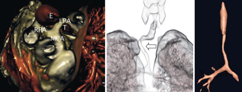
Fig. 13.18
Pulmonary artery sling. Three-dimensional rendered images obtained by computed tomography in a patient with anomalous origin of the left pulmonary artery from the right pulmonary artery. Left panel, anomalous left pulmonary artery (LPA) as it arises from the posterior aspect of the right pulmonary artery (RPA) and courses behind the trachea (T) and anterior to the esophagus (E) to reach the left hilum. Examples of associated tracheobronchial anomalies that can be seen in this vascular anomaly include a “corkscrew-type” (arrow) deformity (middle panel) and complete tracheal rings with absence of the membranous trachea causing airway narrowing (right panel). Both of these entities frequently result in airway compromise. MPA main pulmonary artery (Images by courtesy of Rajesh Krishnamurthy, MD)
Pathophysiology
Although a pulmonary artery sling may present as an incidental finding, the unusual course of the anomalous vessel behind the trachea or right bronchus frequently leads to distortion of the tracheobronchial tree, airway compression, and respiratory symptoms in early infancy. The airway compromise occurs regardless of the presence of associated congenital tracheal stenosis. In some cases, the anomalous left pulmonary artery displays stenosis and/or hypoplasia. The clinical manifestation of this defect can be influenced significantly by the presence of coexistent anomalies.
Management Considerations
The high incidence of tracheal anomalies in this lesion requires comprehensive airway assessment to formulate suitable management plans [53, 60]. The surgical approach in most cases consists of left pulmonary artery division and reimplantation into the main pulmonary artery, allowing for the vessel to be positioned anterior to the trachea. This procedure is now accomplished at most centers via a median sternotomy approach using cardiopulmonary bypass [53, 61]. Concomitant repair of tracheal stenosis and associated intracardiac anomalies is performed as indicated [62–65]. If short-segment tracheal stenosis is present, resection of the involved region is performed; while the trachea is divided, the left pulmonary artery can be translocated anterior to the trachea, obviating the need for surgical division and left pulmonary artery reimplantation.
Applications of Transesophageal Echocardiography
In addition to TTE, other imaging modalities such as chest CT scanning and MRI play important roles in identifying and defining the details of the anatomy in the patient with a pulmonary artery sling prior to surgical intervention [54, 60, 66–74]. At the same time, these additional imaging studies allow for the airway to be examined. The characteristic finding is that of the abnormal origin and course of the vessel. Depending on the particular diagnostic study, an anterior indentation of the esophagus is seen, in contrast to other types of vascular rings, which produce a posterior indentation of the esophagus.
Because of concerns related to frequently associated airway pathology and potential for respiratory decompensation due to esophageal instrumentation, serious consideration of the risk-benefit ratio should be given prior to the use of TEE in affected patients, particularly considering that the anatomic abnormalities usually have been thoroughly outlined. Epicardial imaging should be considered a potentially safer alternative in this case. Another reason for hesitation relates to possible alterations in pulmonary blood flow caused by vascular compression of the anomalous vessel, which can be impinged between the trachea and the esophageal probe. All these factors have discouraged the routine use of TEE in this anomaly and likely account for the limited experience. The discussion that follows highlights known or potential applications of TEE when used in this setting.
Goals of TEE Prior to Surgical Intervention
Characterization of the Anomaly
TEE can confirm or refine the preoperative diagnosis in patients undergoing surgical repair of a pulmonary sling, particularly if concomitant defects are present. The ME Asc Ao SAX and UE PA LAX views using sweeps of the imaging plane obtained by clockwise-counterclockwise rotation to visualize the main and branch pulmonary arteries should display the vascular anomaly. In this interrogation, only the right pulmonary artery origin from the main pulmonary artery is visualized if one scans proximally, in contrast to the normal pulmonary artery bifurcation. If the right pulmonary artery is examined slightly more distally, the origin of the left pulmonary artery might be seen posteriorly (Fig. 13.19, Video 13.9). Although the pulmonary artery bifurcation may appear to have moved rightwards, this finding should not be interpreted as normal. The 2D examination should allow for measurements to be made of the pulmonary arteries to assess for the degree of vessel dilation, stenosis, or possible associated hypoplasia. Doppler interrogation using spectral and color flow modalities facilitates characterization of the anomaly (Fig. 13.20, Video 13.10). In addition to the cross-sections described above, deep transgastric imaging (DTG LAX and DTG Sagittal views) may on occasion assist in the evaluation of a vascular sling, particularly if scanning sweeps are performed.
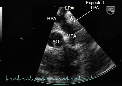
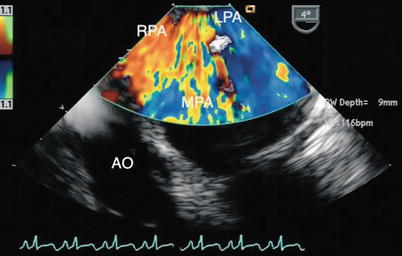
Fig. 13.19
Pulmonary artery sling. Upper esophageal pulmonary artery long axis view of a pulmonary artery sling. The image demonstrates the abnormal takeoff of the left pulmonary artery (LPA) from the right pulmonary artery (RPA). Note the lack of a normal main pulmonary artery bifurcation that typically would occur more proximally relative to the pulmonary valve (approximate expected site of normal LPA origin noted). The anomalous course of the LPA with respect to the trachea (white asterisk) is shown. AO aorta, MPA main pulmonary artery
Fig. 13.20
Pulmonary artery sling. Color Doppler image of the same cross-section depicted in Fig. 13.19 obtained in a zoom mode. Note flow into the left pulmonary artery (LPA) as it arises from the right pulmonary artery (RPA). AO aorta, MPA main pulmonary artery
The findings in a pulmonary artery sling should not to be confused with those of an early takeoff of the right upper lobe pulmonary artery or other vascular anomalies in which the left pulmonary artery originates from the systemic circulation (to be discussed in the section that follows). The demonstration of the origin and course of the left pulmonary artery is essential in this distinction. On TTE, a PDA or left atrial appendage can be mistaken for a normal pulmonary artery, leading to a diagnostic error [67], and it may also confound the TEE evaluation. Partial forms of pulmonary artery sling have been described in which the left pulmonary artery arises from the bifurcation normally, but one of the left lobar branches originates from the right pulmonary artery and courses in anomalous fashion similar to that of the classic form of pulmonary artery sling [75, 76]. This lesion has been identified by transthoracic imaging and, although not yet documented, TEE may also be able to assist in the characterization of this malformation. The finding of a ‘normal bifurcation’ in this defect may also confound the examination of a partial sling if the echocardiographer is not familiar with this anomaly and the more distal right pulmonary artery is not examined to identify the anomalous origin of the lobar branch.
TEE has been shown to be of benefit in the identification of the abnormal origin and unusual path of the left pulmonary artery in this lesion, but some limitations have been identified [77]. Although color Doppler echocardiography enhances the assessment, the origin of an anomalous vessel or entire course behind the trachea may not be readily delineated, even using the combination of standard and modified scanning planes. Spectral Doppler can be used to provide information regarding severity of pulmonary artery obstruction if present. The caveat to this approach is that optimal beam alignment may not be feasible, and the severity of the obstruction can be underestimated if flow to the distal pulmonary vascular bed is limited.
Additional Applications
TEE in this setting is of value in the evaluation of associated defects (such as tetralogy of Fallot) and for intraoperative monitoring [78].
Goals of TEE After Surgical Intervention
Postsurgical Assessment
If TEE is used, the postoperative study should assess the repair by examining the anastomotic connection of the left pulmonary artery to the main pulmonary artery and the nature of blood flow across the corresponding site. This assessment is important considering that tension can be created at this site or a left pulmonary arterioplasty may be required to address associated branch hypoplasia. The results of additional surgical interventions for coexistent defects should also be examined.
Anomalous Origin of a Branch Pulmonary Artery from the Aorta
Anatomic Features
Anomalous origin of a branch pulmonary artery branch from the aorta is a rare congenital malformation. In this anomaly, a main pulmonary segment arises normally from the right ventricle, but only one branch emerges from the pulmonary artery confluence, and the controlateral branch originates from the ascending aorta, resulting in discontinuity between the pulmonary arteries.
Several theories have been proposed to explain the developmental alterations leading to this anomaly, but no consensus has been reached [79–81]. Although this malformation has also been referred to as hemitruncus, anatomically it should be distinguished from truncus arteriosus because, in contrast to a single semilunar valve, two semilunar valves are present in this setting. This anomaly represents less than 0.1 % of all CHD.
Although the anomaly described above of an aortic origin of a branch pulmonary artery represents the most common form of this lesion [82], the anomalous vessel can originate elsewhere [83]. In some cases, the pulmonary artery originates from unusual locations, particularly in the context of complex cardiovascular malformations [84]. It has been proposed that proximal anomalous origin of a pulmonary artery from the ascending aorta and anomalous origin from the innominate artery, also referred to as absent or occult pulmonary artery [85, 86], are two distinct and separate entities from the standpoint of embryology, clinical presentation, and treatment [87–89].
Stay updated, free articles. Join our Telegram channel

Full access? Get Clinical Tree


