The complexity of device follow-up for pacemakers, implantable cardioverter-defibrillators (ICDs) and cardiac resynchronization therapy (CRT) systems has paralleled the increasing sophistication of the devices. Follow-up therefore requires a dedicated staff with a thorough understanding of implantable devices. Traditionally, the purpose of device follow-up has been to ensure appropriate device function. Implanted devices continue to acquire an increasing amount of data, both physiologic and device-related, to permit assessing health status, with the goal of notifying caregivers before clinical decompensation occurs to permit clinical intervention.
Follow-up of permanent pacemakers can be accomplished in more than one way: periodic visits to a pacemaker clinic; less frequent clinic visits in combination with trans-telephonic monitoring (TTM); and/or surveillance via web-based downloads. Follow-up of ICDs and CRTs can likewise be accomplished in more than one way: periodic visits to an ICD clinic or significantly less frequent visits in combination with remote access monitoring. In addition to routine checks, patients on a remote-monitoring network are able to transmit data if they are symptomatic which can limit travel time, clinic visits, and costs. Remote access monitoring represents the most significant advance in device follow-up in decades and is now widely embraced in the USA and Europe and gaining popularity in other parts of the world. Implanted devices may also incorporate external sensors such as a weight scale or blood pressure monitor. Physiologic information is wirelessly transmitted to a hub, from which it can be processed and sent to clinicians.
TTM for pacemakers may eventually be completely supplanted by web-based remote monitoring given the significantly greater amount of clinical decision-making information that can be gained. However, given the current penetration of TTM in the USA, this technology will probably continue to be in use to some degree for a number of years.
TTM can be performed by the implanting center or by a commercial monitoring firm. Follow-up solely by TTM is suboptimal, because some patients undergoing pacemaker implantation may not be seen again until battery depletion indicators appear. Periodic clinic visits allow thorough evaluation and, if necessary, alteration of output settings, rate-adaptive settings, and other parameters. Few patients would obtain maximum efficiency of their pacemaker if it remained at nominal or initially programmed values for the life of the pulse generator.
Remote access monitoring requires implantation of a compatible device. With inductive systems the patient holds a wand over the device to activate remote monitoring; the patient’s unit is typically connected to a phone line or to the cellular phone network to transfer data via the internet to a privacy-protected website. “Wandless” systems incorporate a radiofrequency transmitter that is positioned so as to be in regular patient proximity, e.g., on a night stand. The implanted device is automatically wirelessly interrogated on a scheduled basis. Depending on specified preferences, caregivers are provided device information through fax, telephone, and/or internet. Furthermore, physicians have access to the website to follow routinely scheduled patient transmissions as well as patient-initiated transmissions. Various levels of alerts are generated by the system if a malfunction is detected, e.g., a high impedance suggesting lead failure or ICD therapies being turned “off.”
Requirements for a Device Follow-Up Clinic
Requirements for a device follow-up clinic are detailed in a consensus statement developed jointly by Heart Rhythm Society (HRS) and the European Heart Rhythm Association (EHRA).1 The text that follows, although largely consistent with the HRS/EHRA consensus statement, is based on the design of our long-standing device follow-up clinic.
Space
Because of the specialized equipment necessary for pacemaker ICD and CRT assessment and follow-up, dedicated space is desirable. There must be adequate space for:
- Patient assessment, programming, and storage of all necessary programmers (Fig. 13.1)
- Electrocardiographic monitoring
- Space for informal exercise both for assessment of rate response and determination of appropriate rate-adaptive parameters and 6-minute hall walk tests that may be used for follow-up of CRT patients
- Teaching tools, e.g., written educational information, DVDs, DVD recorder and screen, heart models (Fig. 13.2)
- Trans-telephonic receiving station or stations (the number of stations required is proportional to the overall volume of calls received) (Figs 13.3 and 13.4)
- Remote access internet stations to receive and review patient transmissions (Fig. 13.5)
- Record storage (even though most storage may be accomplished by computerized databases, in many centers some room is required for “paper storage”)
- Resuscitative equipment.
Fig. 13.1 Outpatient area for device programming. The chair reclines to a semisupine position. The programmers surround the area for easy access to any one of them.
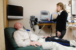
Fig. 13.2 Various teaching materials available in the outpatient area: we have an educational DVD about pacemakers and another about implantable cardioverter-defibrillators (ICDs). The patients see the DVD at the time of the device implant and are sent home with one for future reference. Also pictured are brochures that educate the patient about the basics of pacemakers, ICDs and cardiac resynchronization therapy devices.

Fig. 13.3 The patient is also sent home with a folder that includes educational brochures and a cover note reiterating post-implant restrictions, future transmission dates and important phone numbers related to device follow-up.

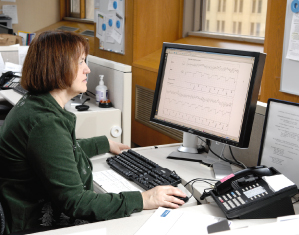
Fig. 13.4 Work area for nurses performing device follow-up, including trans-telephonic monitoring. With digital storage of electrocardiographic tracings, reliance on the electronic medical record and availability of technical manuals on-line, the computer terminal and phone are the major requirements.
Fig. 13.5 Mayo Clinic, Rochester, has a large device follow-up area. Depicted here is the area where trans-telephonic and remote monitoring is performed with stations for up to eight registered nurses.
Personnel
Personnel requirements in the pacemaker clinic include the following:
- Allied professionals with expertise in pacemaker and ICD programming and follow-up (among them may be registered nurses, specially trained technicians, certified technologists [in some countries], physician assistants, and nurse practitioners)
- Secretarial support may be desirable if patient correspondence, appointments, billing, etc., is not automated by the device follow-up system and/or managed by other areas of the institution.
Equipment
Equipment requirements include the following:
- Electrocardiographic (ECG) monitoring (this could be and is most commonly accomplished by the programmers. However, because independent monitoring is helpful in some situations, multichannel ECG monitoring should ideally be available.) Full 12-lead electrocardiography remains useful for assessment of CRT devices
- Programmers for all devices followed (Fig. 13.1)
- Reclining chair or examining table for patient evaluation (Fig. 13.1)
- Resuscitative equipment including external cardioversion defibrillation
- Trans-telephonic receiving station or stations
- Computer access to remote monitoring websites (Fig. 13.5).
Pacemaker Follow-Up
Trans-Telephonic Monitoring
TTM has been part of pacemaker follow-up for over 40 years (Fig. 13.6). For many years, this follow-up method was used primarily in the USA and never gained significant popularity in other countries. Although still used widely in the USA, this technique is increasingly being replaced by web-based remote access.
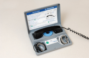
Fig. 13.6 Typical equipment used by the patient for trans-telephonic monitoring. In addition to the telephone, the patient requires a transmitter and electrodes. Various types of electrodes can be used. During electrocardiographic transmission, the patient is instructed to transmit for approximately 30 s. However, if the transmission needs to be interrupted for any reason, an alarm can be sent from the receiving center. If the patient hears the alarm, he or she is instructed to stop the transmission attempt and pick up the phone.
TTM is an effective method to monitor pacemaker battery status and to demonstrate normal or abnormal function. Admittedly, trans-telephonic assessment of atrial events is much more difficult than assessment of ventricular events. In large part the reason is simply the small amplitude of the atrial signal, whether paced or intrinsic. The pacemaker artifact may overwhelm the atrial event, whereas the usually larger ventricular event is not commonly overshadowed by the ventricular pacing artifact.
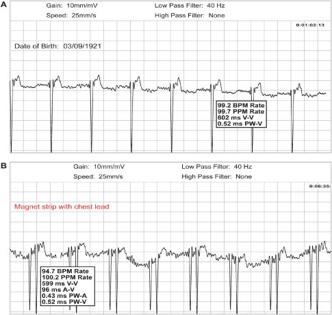
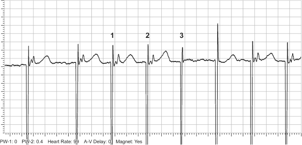
Obtaining TTM tracings of good quality can be an issue. Patients with pacemakers are often elderly, and without excellent initial teaching and possibly coaching during the TTM calls, they may have difficulty handling the trans-telephonic equipment. We request that a family member or friend be present during the initial teaching session. It is often reassuring to the patients to know that someone else has the information necessary to complete the transmission should they forget a portion of the instructions. Transmission difficulties may be compounded if the patient has a significant hearing deficit. Incorrect use of the trans-telephonic transmitter and improper magnet placement may impair the quality of the transmission (Fig. 13.7).
Fig. 13.7 (A) Upper tracing obtained during magnet application in a patient with a pacemaker programmed to a dual-chamber mode. Only the ventricular pacing artifact is seen. This tracing was obtained with the patient using “wrist bands” (bracelets) for the transmission. (B) Lower tracing obtained from the same patient but using a chest lead, i.e., removing the wrist band from the wrist and establishing contact between the electrode of the wrist band and the chest. Even though there is significant artifact present, both the atrial and ventricular pacing artifacts can now be seen.
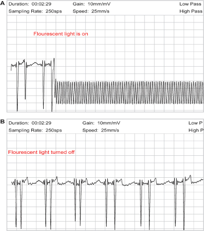
Some types of telephones may be suboptimal for TTM. For example, with cordless phones the quality of transmission at times is decreased and there is sometimes a greater chance of being disconnected. Speaker phones and phones with altered volume controls may also present problems. Any source of electromagnetic interference close to the site of the patient’s transtelephonic transmission may induce significant artifacts (Fig. 13.8). Cell phones have also been problematic but technology is being further developed to allow for cell phone transmission.
Fig. 13.8 (A) Upper tracing obtained during transtelephonic monitoring. Significant artifact is present making interpretation of the tracing impossible. When the patient was queried, it was noted that a fluorescent light next to the transmission equipment was turned “on.” (B) The bottom tracing was obtained after the fluorescent light was turned “off”; artifact is no longer present.
The frequency of TTM differs among centers. At this time, reimbursement for TTM generally is not allowed for more frequent follow-up than that specified by the Centers for Medicare and Medicaid Services (CMS) guidelines.
Equipment
To perform TTM, the patient must have access to the necessary TTM equipment. Typical transmitting equipment is shown in Fig. 13.6. Transmission requires contact with the patient’s skin, i.e., most commonly electrodes on the wrists or the chest. After calling the pacemaker clinic or commercial follow-up center the patient places the telephone over the transmitting equipment. In the pacemaker clinic a receiving center is used to obtain the ECG tracings the patient transmits (Fig. 13.3).
Multiple varieties of electronic medical records as a repository for implantable device data exist including institution-designed, institution-specific systems; and commercial systems. The most commonly used commercial system is the Medtronic Paceart® System (www.paceart.com). The Paceart® System will organize and archive relevant patient, device, programmer, trans-telephonic, and remote management system information for follow-up of arrhythmia patients with implanted cardiac devices. Paceart® supports a common workflow by managing information for all leading manufacturers’ devices and serves as the link to electronic health record systems.
Paceart® standardizes patient and device information. The report format is consistent across all manufacturers’ devices (Fig. 13.9). It provides active device and lead information, current programming, data/telemetry information, and trending device performance. The system also provides functionality for creating physician correspondence and scheduling patient follow-ups for both in-clinic and remote systems. The system will also assist in charge and billing management and provide documentation of in-clinic and remote patient management activities.
Fig. 13.9 Paceart® report format providing active device and lead information, current programming, data/telemetry information, and trending device performance.
Trans-Telephonic Monitoring Sequence
Compared to web-based remote monitoring, the information that can be obtained trans-telephonically is limited. The order in which the information is collected may vary. The following sequence is used by our clinic.
- Brief discussion with the patient to determine general well-being and elucidate any problems the patient believes may be related to the pacemaker
- Nonmagnet “free-running” tracing (duration ≈ 30 s)*
- Magnet tracing (duration ≈ 30 s)*
- Patient informed of pacemaker status; date of next TTM transmission or clinic visit scheduled
- TTM data stored.
If the nonmagnet tracing displays intrinsic rhythm, the underlying rhythm should be noted and compared with previous transmissions. If there is intermittent pacing or pacing in only one chamber of a dual-chamber device, sensing of intrinsic activity can be assessed.
The magnet tracing should be used to assess:
- Capture verification in all chambers paced
- Magnet rate
- Pulse width.
Magnet response varies not only from manufacturer to manufacturer, but also among models from one manufacturer (Fig. 13.10). Specific magnet response for many different devices is difficult to commit to memory. Therefore, it is helpful to have the specific magnet response recorded on the patient’s records. The healthcare professional taking the transmission should be familiar with the elective replacement indicators (ERI) for the specific pacemaker (Table 13.1). Measurements from the patient’s previous transmission should be available for comparison.
Table 13.1 Magnet response and ERI for permanent pacemakers.
| Magnet application* | |
| Biotronik | With “Asynchronous” magnet option*: pacing; In dual-chamber devices, the AV delay reverts to 100 ms; magnet rate dependent on battery status as follows: 90 ppm = beginning of life 80 ppm = ERI |
| Boston Scientific | Asynchronous pacing; In dual-chamber devices, the AV delay reverts to 100 ms; magnet rate dependent on battery status as follows:
|
| Medtronic | Asynchronous pacing; For dual chamber modes, PAV delay reverts to programmed value following three TMT beats with 100 ms PAV. Following three 100 ppm TMT beats all modes pace at:
|
| Sorin Medical | Asynchronous pacing; In dual-chamber devices, the AV delay reverts to original programmed sensed AV interval but with magnet removal the next six cycles will have a 95-ms AV Delay to show capture at the programmed output. The final two cycles of the eight following magnet removal will again be at the rest (max.) AV Delay; magnet rate dependent on battery status as follows:
|
| St. Jude Medical | Asynchronous pacing; In dual-chamber devices, the AV delay reverts to 120 ms; the rate decreases in steps and final rate reveals battery status:
|
AV, atrioventricular; ERI, elective replacement indicators; TBT, Threshold Margin Test.
*Three programmable magnet response options: Auto, Asynchronous and Synchronous; although default is Auto, asynchronous most commonly used. Synchronous mode is used for “patient-triggered monitoring.” Auto mode is 90 ppm for 10 beats then reverts to programmed base rate.
Fig. 13.10 Composite of magnet responses from three pacemakers. Magnet response, top to bottom: (A) Pacemaker goes to 100 bpm for three beats (Threshold Margin Test) followed by asynchronous pacing at programmed lower rate. (B) Asynchronous pacing at programmed lower rate. (C) Asynchronous pacing at 98 ppm.
Other specific information can sometimes be obtained from specific pacemakers. The proprietary Threshold Margin Test (TMT) provides some information on pacing threshold at the onset of magnet application (Fig. 13.11). The first three pacemaker artifacts occur at a rate of 100 bpm. As part of the TMT, the pulse duration of the third pacemaker stimulus is 75% of the programmed pulse duration. Failure to capture with the reduced pulse duration provides some information about threshold and pacing margin of safety.
Fig. 13.11 Tracing from trans-telephonic monitoring demonstrating a threshold margin test (TMT). There is failure to capture on the third artifact at 100 bpm. During the TMT the pulse width on the third artifact is decreased by 25%. Failure to capture by that artifact would demonstrate capture threshold to be very close to the programmed output.
Internet-Based Remote Monitoring
Pacemaker surveillance with internet-based remote monitoring is increasingly used with current generation pacemakers. Internet-based remote monitoring is used almost routinely in some centers for high-voltage devices. Internet-based follow-up is described below for both pacemakers and high-voltage devices.
Pacemaker Clinic Follow-Up Visit
The detail required during the pacemaker clinic visit depends on the follow-up technique or techniques used. If the pacemaker is not capable of internet-based remote monitoring, our practice is to follow the schedule and guidelines in Table 13.2 or at any time that the patient has a concern that may be device-related. At the time of each device clinic visit, the following steps are completed for the pacemaker patient:
- Retrieval of previous data and follow-up records for comparison
- Discussion with the patient about concerns and interim events
- Device interrogation
- Assessment of stored data from prior encounters (TTM/remote/in-clinic)
- Programming sequence
- Assessment of rate-adaptive parameters as needed
- Radiographic assessment if there are clinical concerns that might be addressed by a radiographic evaluation
- Update of medical record.
Table 13.2 Mayo Clinic Guidelines for routine follow-up of pacemaker and ICD patients.
|
*There are specific exceptions as a result of devices that historically need battery check more frequently.
Retrieval of Previous Data and Records
At the onset of the device clinic visit the patient’s prior records should be available. These should include information from the patient’s previous clinic visits and most recent trans-telephonic or web-based transmissions.
Discussion and Interview
The patient should be interviewed in an attempt to elucidate any clinical problems that could be pacemaker-related (Table 13.3). It is important to have some knowledge of the most commonly noted pacemaker problems. These are discussed in detail in Chapter 10: Troubleshooting.
Table 13.3 Common symptoms and possible pacemaker related causes.
Source: Modified from Goldschlager N, Ludmer P, Creamer C. Follow-up of the paced outpatient. In: Ellenbogen KA, Kay GN, Wilkoff BL, eds. Clinical Cardiac Pacing. Philadelphia: WB Saunders Co., 1995: 780–808, by permission of WB Saunders Co.
| Symptoms | Considerations |
| Palpitations | Rapid paced ventricular rates |
| Tracking of sinus tachycardia or supraventricular arrhythmia | |
| Pacemaker-mediated tachycardia | |
| Atrial failure to capture with retrograde conduction and tracking of the premature atrial contraction | |
| Intrinsic (nonpacemaker-related) tachyarrhythmia or extra systoles | |
| Weakness, fatigue, malaise | |
| Pacemaker syndrome | |
| Failure to capture | |
| Inappropriately programmed rate-adaptive parameters | |
| Disease process unrelated to the permanent pacemaker | |
| Dyspnea | |
| Pacemaker syndrome | |
| Underlying cardiac or pulmonary disease | |
| Hiccups | Phrenic nerve stimulation |
| Muscle stimulation | Current leakage in unipolar configuration |
| Loss of insulation integrity of the pacing lead | |
| Presyncope, syncope | Pacemaker syndrome |
| Failure to capture | |
| Oversensing with inhibition | |
| Vasodepression | |
| Cough | Pacemaker syndrome |
| Chest pain | Pacemaker syndrome |
At our institution, the pacemaker clinic does not serve as the primary healthcare or cardiac care provider and the extent of the physical examination is limited to whatever may help detect suspected problems. For example, if no clinical problem is suspected, the examination is limited to inspection of the pacemaker site.
At other centers the device clinic may serve as the primary healthcare provider and visits may include a complete physical examination at periodic visits.
Assessment of Stored Data
In some pacemakers, initial interrogation results in a printout of stored data. In other pacemakers, these data must be specifically requested. It may be necessary to obtain stored data before programming because a permanent change in programming may “clear” stored data in some devices.
Contemporary pacemakers may have the capability of storing a great deal of data. Although the storage capabilities increase with each successive pacemaker generation, at the time of manuscript preparation, select devices have the ability to store up to 1 megabyte of data. The data can provide invaluable assistance in achieving optimal programming and in diagnosing intermittent symptoms. Although stored data has improved with each new generation of devices there are potential limitations of stored diagnostic function. Limitations include low sensitivity and specificity for some events such as device determination of a pathologic atrial tachyarrhythmia. Stored intracardiac electrograms (EGMs) are a critical component in confirmation of stored diagnostic data and follow-up of stored events.
Categories of stored information include:
- Event counters (Fig. 13.12)
- Rate histograms (Fig. 13.13)
- Electrograms (Fig. 13.14)
- Measured values (Fig. 13.15)
- Special diagnostic features (Fig. 13.16).
Fig. 13.12 Telemetered data classifying cardiac events as paced or sensed for both atrial and ventricular channels.
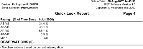
Fig. 13.13 Telemetered data displaying rate histogram, i.e., distribution of heart rates since the counters were previously cleared.
(Courtesy and copyrighted by St. Jude Medical.)
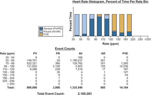
Fig. 13.14 Telemetered intracardiac electrograms from a patient with a biventricular pacemaker programmed to the DDDR mode. The atrial electrogram documents an atrial tachyarrhythmia. Biventricular pacing occurs at a regular rate consistent with mode-switching.
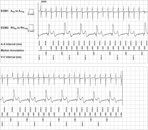
Fig. 13.15 Telemetered data of battery voltage, battery impedance, lead impedance, intrinsic amplitude measurement, and sensing integrity counter from a dual-chamber ICD.
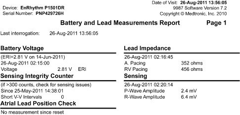
Fig. 13.16 Telemetered data of diagnostic information about atrial and ventricular events that meet criteria for “high rate.”
Programming Sequence
A specific sequence should be adopted and followed for interrogation and programming. Our pacemaker clinic staff has adopted the in-clinic sequence detailed in Table 13.4.
Table 13.4 Guidelines for routine pacemaker interrogation and programmed parameters.
1 Turn on programmer and attach ECG cables 2 Place programmer head/wand over device 3 Initiate interrogation if programmer has not already done so 4 Print initial printout of programmed parameters 5 Check battery voltage and estimated remaining longevity 6 Assess data for any mode switch episodes, atrial or ventricular high rate episodes, electrograms, % pacing, histograms, etc. 7 Obtain real-time rhythm strip 8 Check underlying rhythm @VVI 30 bpm for pacemaker dependency. Obtain rhythm strip 9 Perform sensing tests to measure P and/or R waves* 10 Obtain/record impedance values 11 Perform threshold test for all chambers paced 12 Check current programming to make sure the outputs are programmed at least 2X the threshold voltage or 3X the pulse width. Also check the programmed sensitivity is at least half the measured P or R wave. Make programming changes if necessary
13 Troubleshoot any problems When troubleshooting elevated LV thresholds, remember the option of programming the various configurations and assessing the threshold in each one. Steps to take:
14 Clear counters if required by the specific device 15 If St. Jude Medical pacemaker, demonstrate and discuss patient alert tones with patient. Document if patient unable to hear auditory alert tones 16 Print final printout of programmed parameters and measured data 17 Double-check changes with another nurse 18 Remove ECG patches and turn off programmer 19 Discuss plan for next follow-up with patient 20 Release patient 21 Clean programmer head/wand and/or ECG cables 22 Enter results in Pacemaker Database “Follow-up” note. Remember to add “Physician Reviewer” 23 Enter “Programming” note in Pacemaker Database if any programming changes 24 Add/update battery longevity information to “Reminder notes” 25 Dictate in Mayo electronic record and complete charge slip as appropriate 26 Schedule patient for next appointment if patient has routine Mayo follow-up 27 File printouts in patient’s folder |
*Reminder: R-wave should not be a PVC but an intrinsic beat.
It is not important that this specific sequence be followed but it is crucial that all steps be completed in some orderly manner to avoid omission of any necessary steps.
Rate-Adaptive Parameter Programming
As discussed in Chapter 9: Rate-Adaptive Pacing, the patient’s rate requirements may change over time. For example, in the chronotropically incompetent patient in whom rate response is restored, the newly found rate response may allow the patient to begin an exercise program and improve conditioning. With subsequent improvement in conditioning, a change in rate-adaptive parameters may be desired, such as higher paced rates and a faster increment in heart rate.
Conversely, if symptomatic coronary artery disease were to develop in a patient with a rate-adaptive pacemaker, it may be desirable to make the rate-adaptive parameters less sensitive to avoid rate-related angina while the coronary artery disease is being evaluated and treated.
We routinely assess exercise informally at the first clinic visit, i.e., at approximately 3 months post-implant in most patients. On subsequent visits the rate response would be reassessed if stored rate histograms suggest that the patient is achieving a less than optimal rate distribution. If the rate histogram suggests suboptimal rate response the rate-adaptive parameters are reprogrammed and informal exercise assessment performed.
The patient is also questioned about normal and desired activity levels. This is especially important the first time rate-adaptive parameters are initiated. However, because activity levels change – increase with better conditioning and improvement in well-being or decrease because of associated medical problems – it is wise to enquire about any change in activity before assessing and possibly altering rate-adaptive parameters.
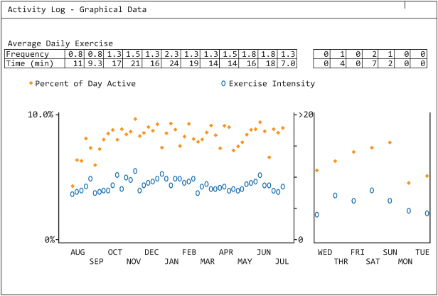
Some CRT devices provide an activity log, i.e., objective evidence of the patient’s activity level. This is especially important in patients with heart failure, because decreasing activity levels may presage the onset of clinical congestive heart failure (Fig. 13.17).
Fig. 13.17 Telemetered information depicting the patient’s activity. The “solid” dots reflect the “% of day the patient was active” and the “open circles” represent the instensity of the exercise. The graph to the left depicts the trend over the prior year and the graph to the right depicts the activity trend over the prior week.
Informal exercise, when needed, can be accomplished in multiple ways depending on available equipment and monitoring. If telemetry is available then the patient should be connected to a wireless monitor and asked to walk at a pace that feels “casual” for a minimum of 2 min. Rates are assessed via telemetry throughout the walk. If the paced rate achieved is felt to be inappropriately low or high for the patient, rate-adaptive parameters can be adjusted and the walk repeated. If the rate response during the “casual” walk seems appropriate for the patient and if the patient is capable of and describes more vigorous exercise as part of his or her daily activities, the process can be repeated with the patient maintaining what they perceive as a “brisk” or “vigorous” cadence. Paced rates are again assessed during this period. For any exercise assessment, formal or informal, the “onset” of the rate change as well as the rate response post-exercise should be assessed. The onset and offset of the rate-adaptive sensor is programmable and can be adjusted if the onset or offset appears too brisk or too slow. For a typical pacemaker patient in his or her sixties or older, with a brisk walk a heart rate of up to 100–110 is expected, and the upper rate is often set to 120. For younger patients, higher upper rate limits are usually programmed. A brisk walk typically uses 50–70% of the expected peak heart rate (calculated as 220 – age).
If wireless telemetry is not available the patient can be connected to the trans-telephonic receiver by wrist electrodes to allow single-lead ECG monitoring and the cable disconnected from the receiver, bracelets left in place, and the patient asked to hold the end of the cable. The patient is then asked to perform the type of walk(s) described above. At the end of the walk, the cable is immediately plugged in, and with the receiving mode at “standby,” the ECG can be obtained at once and heart rate recorded that should be near the peak heart rate achieved. If telemetry is available, it is the preferred method of monitoring the patient during exercise. Alternatively, the rate histogram can be assessed for the focused period of informal exercise.
For the patient who exercises vigorously, formal exercise may be important. If formal (treadmill) exercise is performed and the rate-adaptive pacemaker being optimized has an activity sensor, the patient should avoid holding on to the treadmill. Holding the treadmill railing may blunt the sensor response and lead to inappropriate programming (Chapter 8: Programming, see Rate programmability section; and Chapter 9: Rate-Adaptive Pacing).
Radiographic Assessment
Radiographic assessment of the pacemaker or ICD may provide critical information. This is discussed in detail in Chapter 11: Radiography of Implantable Devices. We do not routinely obtain a chest radiograph for every visit to the device clinic. For the patient with any implanted device, a chest X-ray is obtained in the event a clinical problem occurs and it is felt that an X-ray may be valuable in the evaluation and management of the patient or before any invasive procedure, such as replacement of the pulse generator. Exceptions include specific leads that have failure modes that are detected radiographically, such as the Riata lead in which a conductor may become exteriorized from the main lead body.2,3
Data Storage
Stay updated, free articles. Join our Telegram channel

Full access? Get Clinical Tree


