Endovascular Interventions— Congenital Heart Disease
Titus Kuehne
The ability of MRI to acquire images with detailed information about anatomy and function has set new diagnostic standards for the assessment of patients with congenital heart disease. Fast imaging techniques have emerged that have extended MRI from a purely diagnostic to a dynamic modality that is suited to guide endovascular interventions and to provide immediate information about the physiologic and anatomic responses to catheter-based treatment. Latest concepts even aim at predicting the hemodynamic outcome of intervention by using MRI data for numerical modeling.
The desire to replace x-ray fluoroscopy by alternative imaging modalities for the guidance of catheter-based intervention is motivated by the association of x-ray with significant exposure to ionizing radiation (1) and contrast media and also its lack of soft tissue visualization and functional data acquisition. As an alternative to x-ray transesophageal echocardiography (TEE) was successfully introduced for trans-catheter closure of atrial septal defects (ASD) and evolved in a short time into an important tool that can substitute fluoroscopy completely (2). The capability of MRI, however, to acquire at any arbitrary orientation in three-dimensional (3D) space real-time images with high soft tissue contrast makes this technique attractive for technically even more demanding procedures. In addition, MRI allows accurate pre-interventional and immediate postinterventional assessment of cardiovascular morphology and function, and thus may simplify catheter-based procedures.
Mortality rates in patients with congenital heart disease have decreased significantly over the past decades. Therefore, in the future the work of clinicians caring for such patients is likely to focus more and more on maintaining low morbid ity and higher quality of life. This requires the development of optimized diagnostic tools to better guide therapy; the establishment of non-ionizing and less invasive interven tional methods; and the progressive replacement of surgical by transcatheter techniques. Moreover, advances in image postprocessing and numerical modeling have opened new perspectives using MRI for virtual surgery and catheteriza tion and for simulating and compare the effects of different treatment strategies.
TECHNIQUES
INTERVENTIONAL MRI UNIT: GENERAL CONSIDERATIONS
Most MRI-guided cardiovascular interventions are conducted in 1.5-T scanners with a short wide bore. Three-tesla and low-field open systems are theoretically also suited, but are limited by higher affinity to susceptibility or lower resolution for real-time cardiac imaging, respectively. The short bore of modern scanners allows reasonable access to the groin or neck of the patient, although catheter manipulation can be difficult in small infants or children (Fig. 38.1).
In the clinical setting, x-ray fluoroscopy is used for almost all endovascular interventions, due to excellent spatial and temporal resolutions in combination with high contrast between vessels and background. Recent developments, such as contrast-enhanced 3D rotational angiography, exploit these features further and open up new possibilities. However, x-ray is still limited in terms of soft tissue visualization and acquisition of quantitative functional parameters. Combined x-ray/MRI units were proposed to take advantage of both imaging modalities. Fahrig et al. (3) reported simultaneous x-ray and MRI by integrating, similar to PET-MRI systems, an x-ray camera into an open 0.5-T scanner. A different strategy is to connect the MRI scanner over a mobile table with C-arms or even fully equipped x-ray angiography laboratories (4,5). The use of such combined units makes sense until MRI catheter-tracking techniques have reached a higher standard in terms
of reliability and safety. Until then an x-ray safety back-up system should be available.
of reliability and safety. Until then an x-ray safety back-up system should be available.
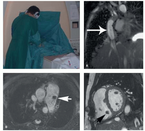 Figure 38.1. MRI catheterization of patients. Panel A: It shows angioplasty balloon inflated with saline solution in a patient with Fontan circulation. Panels B,C: They show flow directional catheters in the pulmonary artery and right ventricle. The catheter tipped balloon is inflated by CO2. The arrows point on flow-directed catheters in the pulmonary artery and right ventricle (lower panels) and an angioplasty balloon catheter in the vena cava (upper right panel). |
The overlay of MRI-derived anatomic roadmaps to x-ray fluoroscopy is used in an increasing number of applications. Such an approach can be applied in combined x-ray/MRI units or, in a sequential approach by importing previously acquired MR images into a conventional catheterization laboratory. Any of such multi-modality imaging requires methods for image registration. For having a kind of overview, registration can be done by anatomical landmarks. For procedures that require more precise information, more sophisticated registration methods need to be applied. Such methods include among others the use of fiducial markers (Fig. 38.2) (6,7).
MRI-compatible equipment for anesthesia and monitoring vital parameters are offered by different manufacturers. In-room display monitors and operation consoles allow image acquisition by an interventionalist and imaging expert standing alongside. An aspect that must be considered when performing MRI-guided intervention is high noise levels during imaging. However, our experience shows that communication can be well adapted to intermittent noise by training of the staff involved in the procedure.
Safety aspects for the use of an interventional MRI unit require that general contraindications for MRI of patients are respected. In addition, the use of interventional instruments must be chosen with their interaction with the magnetic field in mind (8,9,10 and 11). Metallic materials that yield significant magnetic torque, such as introducer needles or wires, must not be brought into close proximity to the magnetic field. In addition, all elongated electrical conductors, metallic or not, are prone to heating effects if they reach the critical length of 20 cm at 1.5 T (10,12,13). Therefore, such interventional instruments must be excluded from en-dovascular manipulation. Further details on the MRI compatibility of catheters, guidewires, and medical implants are provided in other chapters.
IMAGING TECHNIQUES
Real-time 3D imaging is a task that remains to be realized. However, MRI already offers an exceptional variety of
two-dimensional (2D) real-time and ultra-fast acquisition modalities for the assessment of anatomy and function. Up-to-date high-gradient systems provide the short TR and TE needed for fast imaging with steady state free precession (SSFP). This acquisition technique in conjunction with spiral or radial filling of the k-space is currently considered one of the most reliable tools for high-quality and robust real-time imaging (14,15).
two-dimensional (2D) real-time and ultra-fast acquisition modalities for the assessment of anatomy and function. Up-to-date high-gradient systems provide the short TR and TE needed for fast imaging with steady state free precession (SSFP). This acquisition technique in conjunction with spiral or radial filling of the k-space is currently considered one of the most reliable tools for high-quality and robust real-time imaging (14,15).
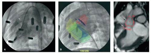 Figure 38.2. Multi-modality imaging by x-ray fluoroscopy and MRI for closure of membranous ventricular septal defects. Image registration is realized by fiducial markers (panel A), the fused images are shown (panel B). MRI provides detailed anatomical roadmaps (panel C). Arrow (panels A, B) position of the ventricular septal defect. In addition, arrow show position of the aortic root (panel C) and guidewire (panel B). |
Nevertheless, during real-time MRI the interventionalist has to find a compromise between temporal and spatial resolutions or signal-to-noise ratio (SNR). In-plane resolutions of 1 mm can be obtained if lower acquisition rates of approximately 5 frames per second are accepted. In contrast, at lower spatial resolutions, frame rates of up to 20 frames per second can be achieved.
It is important to note, that x-ray fluoroscopic frame rates of less than 10 frames per second are often applied in order to minimize the radiation exposure of the patient. In addition, MRI allows interleaved high-resolution imaging if needed. The rationale for MRI would be the transition between different imaging sequences that provide either high-spatial/low-temporal or low-spatial/high-temporal resolution.
Accurate assessment of cardiovascular morphology prior to the intervention can facilitate the procedure and reduce its duration. The acquisition of high-quality whole-heart imaging provides detailed 3D information that can be used as an anatomical roadmap when overlaid to real-time images or x-ray in combined units (7,16). Such multi-modality imaging approaches are known for electrophysiology studies but are also promising for closure of ventricular septal defects or performing myocardial biopsy (17).
High-quality MRI of anatomy in combination with MRI-derived blood flow provides valuable information that permit simulating different interventional or surgical treatment strategies prior to the actual procedures. Thus such approaches enable to determine for the individual patient the type of treatment that offers optimum outcome (Figs. 38.3 and 38.4) (16,18).
Multi-modality imaging that fuses MRI or CT images with x-ray fluoroscopy is routinously applied in electrophysiology studies. In a more experimental level, such methods were described for guiding myocardial biopsy and closure of VSD (17). These approaches will be described in more detail in the chapters below.
MRI CHARACTERISTICS OF MEDICAL IMPLANTS
To date most medical implants used in cardiovascular medicine comprise at least in part metal alloys that can cause artifacts on MR images. Such devices include endovascular stents or stent-prostheses, septal or duct occluders, embolization coils, and prosthetic heart valves. These implants are generally not a contraindication for MRI studies: They yield only minor magnetic torque and heating and therefore can be considered MRI compatible in terms of patient safety (8,19,20). However, susceptibility artifacts of the metallic device can cause pitfalls or even make assessment of cardiovascular morphology and function impossible (20).
The extent of imaging artifacts depends mainly on the paramagnetic properties of the device and the field strength of the magnet. Less important factors are material thickness, the orientation of metallic struts toward the B0 field direction, and the sequence parameters used during MRI.
Metals with weak paramagnetic properties, such as nitinol, yield susceptibility values that are relatively close to those of human tissue and therefore cause only slight local imaging artifacts (21,22,23 and 24). By contrast, metals with strong paramagnetic properties, such as stainless steel, produce severe image distortion (22,23 and 24). Furthermore, the extent of susceptibility is directly related to the magnetic field strength. MR scanners with high field strengths cause more susceptibility artifacts than scanners with low field strengths (8,25). Finally, parallel alignment of a metallic strut to the B0 field direction causes fewer artifacts than orthogonal alignment (25,26). However, the orientation of a metallic implant toward the field direction is obviously difficult to predict in the clinical setting.
The MR artifact behavior of endovascular stents is further complicated by radiofrequency shielding effects. Shielding effects are caused by eddy currents on the surface of the stent
that prevent radiofrequency pulses from fully penetrating the wire mesh. This results in decreased signal intensities within the lumen of the stent. The obscured lumen can be misinterpreted as in-stent stenosis or obstruction (21,26,27 and 28).
that prevent radiofrequency pulses from fully penetrating the wire mesh. This results in decreased signal intensities within the lumen of the stent. The obscured lumen can be misinterpreted as in-stent stenosis or obstruction (21,26,27 and 28).
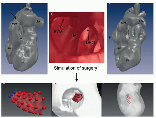 Figure 38.3. MRI 3D whole-heart -based cast models of the heart of a patient with complex double outlet right ventricle (which means that the pulmonary artery and the aorta arise from the right ventricle (RV). The upper panels shows the cast before (left) and after surgery (right panel).The asterix indicates the position of the ventricular septal defect through which a surgical conduit is positioned (dotted line, right upper panel) in order to connect the left ventricle (LV) with the aorta.The upper mid panel is a magnification with a view through the ventricular septal defect into the RV. Computer-assisted methods allow for the simulation of the surgical procedures. In this patient the size, form, and position of the conduit form is determined prior surgery. The results of the simulation were confirmed after surgery (upper right panel). MPA, main pulmonary artery with banding (arrow); RVOT, right ventricular outflow tract; LVOT, left ventricular outflow tract; LPA, left pulmonary artery; Ao, aorta. |
The impact of pulse sequences for minimizing susceptibility or radiofrequency shielding was investigated in several studies (23,24,27,29,30). The use of large flip-angle can reduce the amount of signal loss by radiofrequency shielding (23,31). Short TE and read recording direction parallel to B0 were reported to reduce dephasing and thus susceptibility (23,27). A further, quite effective sequence implement is 180 degrees refocusing pulses, as used in spin-echo imaging. However, artifacts on spin-echo images must be carefully interpreted because remaining radiofrequency shielding and residual susceptibility artifacts cannot be easily differentiated from the dark blood pool, and thus in-stent stenosis could be falsely overlooked.
Endovascular Stents
MRI has been proven to be an effective noninvasive tool to assess vascular stenosis (32,33). However, the evaluation of in-stent stenosis, a frequently encountered problem, is difficult using MRI due to susceptibility artifacts and radiofrequency shielding effects of the stent.
Numerous in-vitro and in-vivo studies have investigated the artifact behavior of clinically available stents and aimed to grade them in terms of their MRI suitability (22,25,28,29,31,34). Although several findings of these studies were not congruent, all studies demonstrated that stainless steel stents are generally not suited for MRI examination due to severe susceptibility artifacts. In terms of susceptibility, platinum and tantalum stents showed intermediate and nitinol stents good results. In addition, the degree of observed radiofrequency shielding varied
greatly between different stent types because specific design properties can either favor or reduce eddy currents and thus RF shielding. In summary, large nitinol and platinum stents of the aorta or pulmonary arteries can be assessed with MRI (Figs. 38.5 and 38.6). In contrast, smaller stents or stents made from stainless steel are not assessable by MRI.
greatly between different stent types because specific design properties can either favor or reduce eddy currents and thus RF shielding. In summary, large nitinol and platinum stents of the aorta or pulmonary arteries can be assessed with MRI (Figs. 38.5 and 38.6). In contrast, smaller stents or stents made from stainless steel are not assessable by MRI.
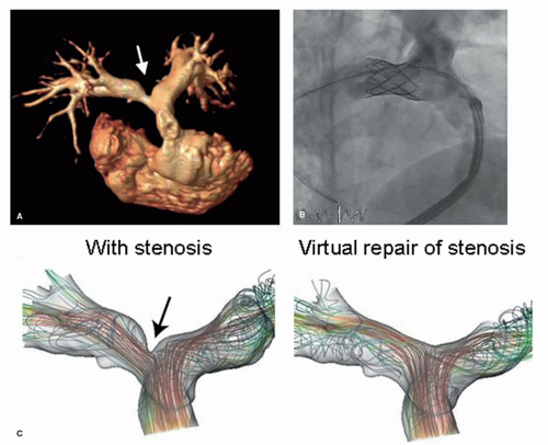 Figure 38.4. MR angiogram of a patient with right pulmonary stenosis (panel A, arrow) with moderate pressure gradient but substantial flow mismatch between the right and the left pulmonary artery. Current guidelines show indication for stent placement. Anatomical information and quantitative flow are used for numerical simulation of the hemodynamic effects of an intervention (panel B). Simulation revealed that stent placement would not improve perfusion mismatch which was later confirmed. |
In some circumstances MR-flow measurements have the potential to overcome, at least in part, the problem of RF shielding for the assessment of stent lumen patency, because phase images do not depend on the amplitude of flip angle excitation (35,36 and 37). Therefore, stenosed stents will not contain any phase information in areas with tissue in-growth or thrombus formation. However, phase images are very sensitive to susceptibility effects and therefore this technique requires stents with both low-paramagnetic properties and relatively large diameter (35,36 and 37). In contrast to metallic stent, bioabsorbable stents have the drawback that they are not visible on MR images at all. Current studies investigate such stents for use in the coronary arteries or as carrier for next generation valved stent devices.
Embolization Coils and Duct Occluders
Most embolization coils are made of platinum or nitinol alloys that produce only slight local susceptibility artifacts (20). On the other hand, some occluders for the closure of patent ductus arteriosus contain stainless steel components that can severely distort MR images due to susceptibility and make assessment of the adjacent pulmonary arteries and thoracic aorta problematic.
Atrial and Ventricular Septal Occluders
Metallic components of atrial and ventricular septal occluders are generally manufactured from a nitinol mesh that
produces only moderate susceptibility artifacts (Fig. 38.7) (38,39). Due to the relatively large size of the device, the artifact can sometimes extend to the adjacent anatomy and make analysis of atrial or ventricular volumes problematic. In contrast, the magnetic torque on such devices is minor and patients can be safely examined with MRI.
produces only moderate susceptibility artifacts (Fig. 38.7) (38,39). Due to the relatively large size of the device, the artifact can sometimes extend to the adjacent anatomy and make analysis of atrial or ventricular volumes problematic. In contrast, the magnetic torque on such devices is minor and patients can be safely examined with MRI.
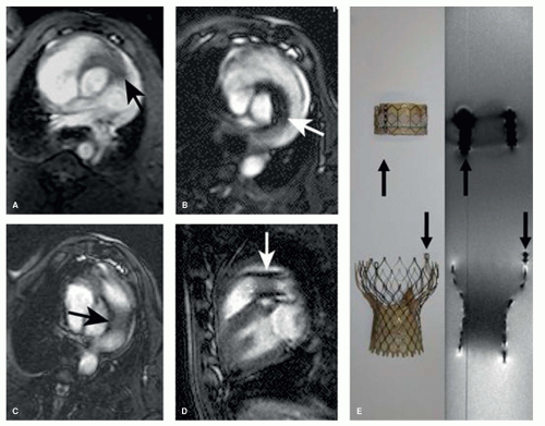 Figure 38.5. Real-time MRI for placement of custom made nitinol valved stents in the pulmonary position. Panels A, D: Material properties of the delivery system and of the stent allow for reasonable visualization by MRI. Many commercially available systems for transcatheter aortic valve position are also made from nitinol and thus suited for MRI-guided intervention. Arrows in panels A-D show the position of the delivery system and the valved stent after implantation. Panel E: It shows the Medtronic Corevalve. The arrows in the panle E show the eylets at the outflow tract of the stent. (Kahlert P, Eggebrecht H, Plicht B, et al. Towards realtime cardiovascular magnetic resonance-guided transarterial aortic valve implantation: In vitro evaluation and modification of existing devices. J Cardiovasc Magn Reson. 2010;12:58.) |
Mechanical Heart Valve Prostheses
Only few mechanical heart valves are known to have contraindication for MRI, including some early models of the Starr-Edwards and Jomed Monodisc prosthesis (40,41). Other mechanical valves are safe with MRI, however, morphologic and to some extent functional assessment is difficult because of susceptibility artifacts (41).
New generations of heart valves are incorporated into carrier stents that can be implanted in selected patients by transcatheter techniques into the pulmonary or aortic valve position. The Medtronic Melody, Medtronic Core Valve, Symetis Acurate, and Jena Valve, have carrier stents made from Nitinol alloys or, for the Melody system, from platinum. Such devices are MRI compatible and they can be well visualized during and after MRI-guided procedures (Figs. 38.5 and 38.6). In addition, after implantation valve function, anatomic position and adverse effects of valved stent can be determined by MRI (42,43 and 44).
MRI TRACKING OF ENDOVASCULAR CATHETERS AND GUIDEWIRES
There are a broad range of catheters that are manufactured for specific cardiovascular applications. Some of these catheters are braided with iron oxides or wire meshes in order to make them radio-opaque or to add flexibility. Such catheters
are generally not suited for use during MRI because they can produce severe image distortion due to susceptibility. On the other hand, catheters made from polyesters only do not generate any signal at all and are therefore invisible during MRI. However, appropriate catheter-tracking methods are essential to perform successful MRI-guided endovascular procedures. Ideally, tracking methods generate high contrast between the catheter and the background anatomy and readily allow automated slice and tip detection. In addition, the method should visualize both the tip of the catheter and its shaft in order to be able to identify possible looping of the catheter. The development of catheter-tracking methods that fulfill all clinical needs is technically very challenging. These difficulties are one of the major barriers that delayed the transition of preclinical interventional MRI into the clinical settings.
are generally not suited for use during MRI because they can produce severe image distortion due to susceptibility. On the other hand, catheters made from polyesters only do not generate any signal at all and are therefore invisible during MRI. However, appropriate catheter-tracking methods are essential to perform successful MRI-guided endovascular procedures. Ideally, tracking methods generate high contrast between the catheter and the background anatomy and readily allow automated slice and tip detection. In addition, the method should visualize both the tip of the catheter and its shaft in order to be able to identify possible looping of the catheter. The development of catheter-tracking methods that fulfill all clinical needs is technically very challenging. These difficulties are one of the major barriers that delayed the transition of preclinical interventional MRI into the clinical settings.
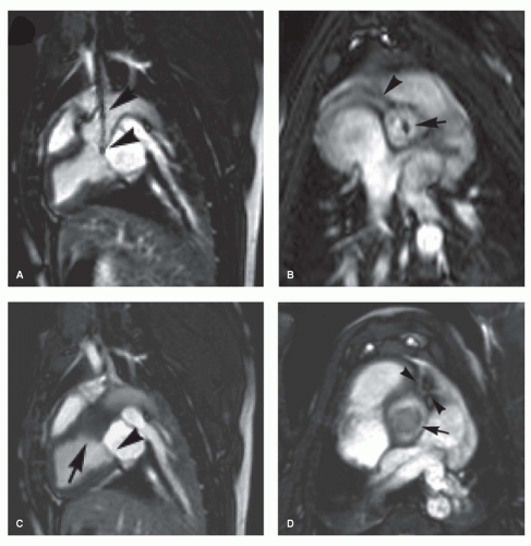 Figure 38.6. MRI-guided transcatheter placement of a valved stent in the aortic valve position in swine. MRI enables continuous visualization of anatomy and interventional instruments. Passive catheter tracking of the delivery system is achieved by the use of two small susceptibility markers that are positioned at the distal and proximal end of the loaded valved stent (arrows, panels A,B). Important anatomical landmarks can be identified during MRI including the coronary arteries or mitral valve leaflet (arrowheads, panels B-D). The position of the implanted valved stent can be clearly identified by slight local susceptibility artifacts and radio-frequency shielding. Panel D: It shows the prosthetic valve leaflets within the valved stent (arrow), the unobstructed orifice, and first segments of the left coronary artery (arrowheads). |
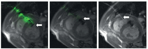 Figure 38.7. MRI-guided closure of apical ventricular septal defect. A transthoracic access sheath is guided under real time and by active tracking through the chest directly into the heart. Arrows show the position of the occluder and of the delivery system. |
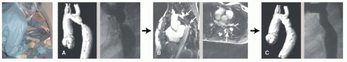 Figure 38.8. Interactive real-time images of a patient with aortic coarctation. Panels A and B show MR and x-ray fluoroscopy angiograms of the aorta before and after intervention. A balloon angioplasty catheter is advanced from the ascending aorta through the coarctation. Angioplasty is performed with an iron oxide-based contrast media (panel B). The contrast medium produces good contrast between the catheter shaft and the balloon and the blood pool of the aorta. The balloon catheter was splinted by a long sheath for stabilization. The vessel lumen was secured by a custom made polymer guidewire. |
Active Tracking
Active tracking is commonly accomplished by incorporating a small receiver coil or antennas into the tip of catheters or guidewires (45,46 and 47). The coil picks up signal during slice excitation and generates frequency-encoded recall echoes. These echoes can be detected in 3D space in real-time and at a spatial resolution of approximately 1 mm (Fig. 38.7). The major drawback of this technique is the need to integrate the electronic components into the catheters. This has direct impact on the mechanical properties and the profile of the catheters. Progress was made in the development of safe transmission lines that overcome potential heating of the catheter tip (48,49 and 50). However, all preclinical devices still require further safety evaluation for obtaining approval for clinical use.
Passive Tracking
Passive tracking techniques aim to directly visualize the interventional instrument within the imaging plane and therefore do not require any additional data postprocessing. Passive techniques are based either on local signal voids due to field inhomogeneities/susceptibility or signal enhancement by the use of specific MRI-contrast media (51,52


Stay updated, free articles. Join our Telegram channel
Full access? Get Clinical Tree
