Endovascular Interventional Magnetic Resonance Imaging
Arno Bücker
ENDOVASCULAR INTERVENTIONAL MRI
INTRODUCTION
Magnetic resonance angiography (MRA) has supplanted x-ray angiography as the first diagnostic step after ultrasound. A competitor to MRA is computed tomography angiography (CTA), despite its disadvantages of ionizing radiation, the need for nephrotoxic contrast agents, and deteriorating accuracy in heavily calcified vessels. The success of MRA in daily routine was made possible by technical progress on the front of sequence development as well as through hardware improvement. While coronary angiography is still a challenge for MRA, the advent of fast gradients with short repetition time (TR) and echo time (TE) enabling breath-held three-dimensional (3D) contrast-enhanced angiography was a breakthrough for the clinical application of MRA in the region of the aorta, its branches, and even for run-off vessels.
The ideal MR sequence for vascular interventions would be the acquisition of a 3D dataset with real-time upgrades of the background anatomy as well as of the interventional device. Of course, both the vascular anatomy and the interventional device would have to be depicted with high spatial resolution. The application of contrast media should not be necessary in order to avoid toxic concentrations of nowadays commercially available contrast agents in case of multiple injections. While the application of blood pool agents can circumvent this problem, the resulting overlap of arterial and venous anatomy is not desirable.
So far, we are still struggling to get close to the ideal situation of real-time 3D imaging for vascular MR interventions. The acquisition of 3D datasets is still too slow to allow realtime imaging. But first attempts for vascular interventions have been successfully performed relying on roadmaps of 3D datasets in conjunction with real-time projection of a catheter tip onto previously reconstructed maximum intensity projections (MIPs) (1). In addition to high temporal, high spatial resolution is also needed, in order to visualize small vessels as well as interventional instruments. These instruments have to be made of non-ferromagnetic material in order to avoid large artifacts. Furthermore, safety aspects have to be considered, which do not allow the use of metallic devices like guidewires, which could act as an antenna (2).
Many of the above-mentioned “challenges” have been, at least partially, met by now, although the ideal solution has not been found yet. Further research is needed to optimize currently applied techniques and instruments before they will be integrated in a clinical routine setup. This is reflected by the fact that almost all of the applications reported have only been performed in animal studies. Despite the unexpected long development time, I am convinced that the technical development of real-time control for endovascular interventional MRI will greatly influence the clinical routine as well and therefore, has its clinical impact even for those who are “merely” applying Magnetic Resonance Imaging (MRI) for diagnostic purposes.
TECHNIQUES
The different requirements for endovascular interventional MR mentioned above have to be fulfilled all at the same time. A real-time imaging sequence will not be acceptable for the
control of interventions if it displays the vascular anatomy without depicting interventional devices at the same time. For didactical reasons the different technical aspects will be discussed separately. But it has to be kept in mind that the need for coordinated functionality and simultaneous fulfillment of all the major prerequisites makes MR control of vascular interventions such a demanding and challenging field of research.
control of interventions if it displays the vascular anatomy without depicting interventional devices at the same time. For didactical reasons the different technical aspects will be discussed separately. But it has to be kept in mind that the need for coordinated functionality and simultaneous fulfillment of all the major prerequisites makes MR control of vascular interventions such a demanding and challenging field of research.
Real-time MR Imaging
As early as 1984, real-time MR imaging has been described in the literature by means of echo planar imaging (EPI) (3). But the spatial resolution of these images has been quite low. This is due to the basic physics of MRI causing a trade-off between spatial and temporal resolutions for the nowadays routinely used Cartesian acquisition of MR images. As each imaging point has to be measured individually, the spatial resolution is directly proportional to the acquisition time of an MR image. Therefore, standard MR techniques yield either images of high spatial and low temporal resolution or vice versa. New imaging strategies like radial and spiral scanning have become essential for vascular MR-guided interventions and will be discussed as far as understanding of the technical details is necessary for performing interventions and as far as the new techniques can be expected to become important for diagnostic real-time imaging, especially of the heart.
Hardware Considerations
The need for speed favors high-field systems for interventional MR. On the other hand, high-field systems offer less patient access compared to open-, mid-, and low-field MR scanners (4). A further disadvantage of high-field systems is the increase of susceptibility artifacts, which can be a problem for the use of metallic devices (5). Considering the need for high-quality diagnostic MR angiographies as well as the prerequisite of real-time imaging capabilities, it can be concluded that high-field scanners of up to 1.5 T will be preferable for the guidance of vascular interventions, although mid-field systems have been successfully applied (1). Up-to-date high gradients are also mandatory for state of the art imaging, because they provide the short TR and TE not only needed for speed but also for high image quality of so-called trueFISP (fast imaging with steady state precession) sequences, which already play a major role for diagnostic imaging of the heart and can be expected to do so for interventions as well. Despite the fact that many articles have been written about possible applications of even low-field magnets for interventional MR in general—like biopsies and thermoablation (6,7)—there have been no reports published about vascular interventions on low-field systems showing a reasonable imaging speed and quality.
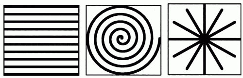 Figure 37.1. The filling of k-space can be accomplished by different strategies. Cartesian (left), spiral (middle), and radial scanning are schematically demonstrated. In order to reconstruct an MR modulus image, central as well as outer parts of k-space have to be covered. The central parts being mainly responsible for contrast and signal. In case of spiral or radial scanning the number of spirals or radials, respectively, are not directly related to spatial resolution. |
Vascular interventions under MR guidance require additional hardware modifications. An in-room monitor is needed beside the magnet in order to be able to directly control the intervention. It should be possible to change the slice position and at least some of the scan parameters on the fly in order to be flexible enough to optimize image quality by changing TR, TE, and flip angle. At least currently, an angiographic backup system is needed to be able to control the success of MR-guided vascular interventions and to be prepared for possible complications and emergencies. In addition, dedicated real-time MR sequences will require special hardware for the real-time reconstruction of the raw data. Different interventional setups fulfill these requirements at least partially and are described in the literature (8,9 and 10).
Sequence Design
MR images are created by collecting raw data in the socalled k-space. The standard acquisition scheme nowadays is Cartesian imaging filling k-space with lines, where each line represents one phase-encoding step (Fig. 37.1). For standard gradient- or spin-echo sequences, the acquisition of one k-space line will require one TR. Consequently, an MR gradient-echo image with a 256 matrix (256 phase-encoding steps) and a TR of 4 milliseconds will still require a total acquisition time of 1 second. The application of fast spin-echo,
gradient-echo techniques, or EPI allows to sample more than one phase-encoding step during one TR period, speeding up the image acquisition. Although imaging in subseconds is possible with either technique, we found neither the image contrast nor the acquisition speed sufficient for the guidance of vascular interventions, at least when compared to other k-space strategies as described below. But Bakker et al. (11) exploit Cartesian imaging for MR guidance of interventions. They showed that on the fly background subtraction greatly improves the visibility of interventional instruments. This requires special hardware modifications in order to calculate and display the images fast enough (12). The frame rate achieved was about one image every 2 seconds consisting of an image acquisition time of 0.5 to 1 second and additional latency due to image calculation and display. Despite this relatively low imaging speed, Bakker et al. were able to perform balloon dilatations in vitro as well as in vivo under MR control (13).
gradient-echo techniques, or EPI allows to sample more than one phase-encoding step during one TR period, speeding up the image acquisition. Although imaging in subseconds is possible with either technique, we found neither the image contrast nor the acquisition speed sufficient for the guidance of vascular interventions, at least when compared to other k-space strategies as described below. But Bakker et al. (11) exploit Cartesian imaging for MR guidance of interventions. They showed that on the fly background subtraction greatly improves the visibility of interventional instruments. This requires special hardware modifications in order to calculate and display the images fast enough (12). The frame rate achieved was about one image every 2 seconds consisting of an image acquisition time of 0.5 to 1 second and additional latency due to image calculation and display. Despite this relatively low imaging speed, Bakker et al. were able to perform balloon dilatations in vitro as well as in vivo under MR control (13).
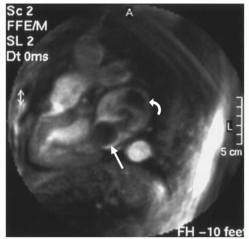 Figure 37.2. A real-time spiral image acquired in 120 milliseconds nicely demonstrates a left atrial myxoma (arrow) on this long-axis view. The dark areas in the left atrium due to turbulent flow (curved arrow) could be easily distinguished from a mass on the real-time movie. |
In terms of fast k-space coverage, spiral scanning is one of the most efficient ways of data sampling. As the name implies, one or more spirals are acquired in order to fill k-space (Fig. 37.1). In theory, one spiral is sufficient to reconstruct an MR image. Usually more than one spiral is acquired and the different spirals are interleaved. The effects of this as well as more refined techniques like partial k-space coverage are beyond the scope of this text and the interested reader is referred to the literature (14,15). Depending on the exact form of the spiral and its length, the acquisition time for one spiral will vary. Spiral scanning does allow acquisition times for one image in the range of 100 milliseconds, allowing, for example, real-time visualization of the beating heart, which makes this technique also interesting for diagnostic imaging (Fig. 37.2). No cardiac triggering is required and therefore, no problems arise due to irregular heart rhythm. The speed of spiral scanning is combined with flow sensitivity which yields good contrast of the cardiac chambers as well as vessels, allowing the application of this technique for vascular interventions. One drawback of spiral scanning is the need for a homogenous magnetic field to avoid major artifacts. This can cause problems when metallic devices are used, which usually will disturb the required homogeneity.
Another sampling technique for k-space is radial scanning (16). Similar to Cartesian scanning, multiple lines are acquired, but these lines fill k-space in a radial manner (Fig. 37.1). Compared to spiral scanning this technique is much less time efficient, because a relatively high number of radials has to be collected in order to avoid streaking artifacts due to severe undersampling and in order to achieve a sufficient signal-to-noise ratio. As the acquisition time of each radial line is comparable to the above-mentioned Cartesian scanning, relatively long imaging times result. Nonetheless, radial scanning is fast enough and can be successfully exploited for the guidance of vascular interventions (17). This is achieved by two means. Some degree of undersampling can be accepted for radial scanning, because the spatial resolution is not directly related to the number of radial lines. Therefore, the spatial resolution is not essentially reduced by undersampling (18), and only a few radials are needed to be able to depict a high contrast structure (Fig. 37.3). In addition, radial scanning can be ideally combined with the sliding window reconstruction technique also called view sharing (19). This reconstruction technique uses partially new data in conjunction with old data to calculate new MR images with a frame rate higher than the acquisition speed for a single complete MR image (Fig. 37.4). This results in an MR movie where fast movements are partially frozen due to averaging. While this feature makes the technique at least theoretically less well suited for diagnostic imaging of heart function, it excellently satisfies the need to visualize a moving interventional device on a basically unchanging background anatomy. One further advantage of this technique is the lack of its susceptibility to motion artifacts (20) allowing, for example, its diagnostic application for the detection of pulmonary embolism without the need for breath-holding (21). Many images in this chapter are acquired by radial scanning combined with the sliding window reconstruction technique, yielding a frame rate of 20 images per second. As the imaging time for one complete MR image is in the range of seconds, there is a minor latency between the movement of the interventional instrument as seen on the real-time images and the actual movement.
Currently, real-time imaging sequences used for MR guidance consist of two-dimensional imaging repetitively acquiring a single slice. Three-dimensional imaging is still too slow to accomplish even near real-time imaging, not to mention the difficulties of maintaining good contrast between vessels and background anatomy. The need for contrast does not allow to apply the principle of projection imaging to interventional MRI. Compared to x-ray, the tomographic nature of MR is clearly a disadvantage in this field. In order to contain the vascular anatomy of interest including tortuous vessels, the acquired single slice should be as thick as possible, while maintaining a good contrast between the vascular anatomy and the background. At the
same time, the depiction of interventional devices has to be considered. While the application of blood pool agents has been shown to be advantageous (22), there are limits to the slice thickness that can be used. Figure 37.5 shows radial images of the ureter, which is of high signal intensity because of the earlier application of gadolinium-DTPA, thereby simulating a blood pool-agent-filled vessel. The growing loss of contrast between contrast agent containing structures and the background with increasing slice thickness is a principle that holds true for all MR sequences, limiting the maximum slice thickness. Furthermore, the use of blood pool agents causes an overlap of venous and arterial anatomy, which can significantly degrade the image quality. This is illustrated by Figure 37.6 showing the intrinsic contrast of radial images. One image displays veins as well as arteries. The other image is acquired with a saturation band saturating the venous flow and thereby allowing for a much clearer depiction of arterial anatomy.
same time, the depiction of interventional devices has to be considered. While the application of blood pool agents has been shown to be advantageous (22), there are limits to the slice thickness that can be used. Figure 37.5 shows radial images of the ureter, which is of high signal intensity because of the earlier application of gadolinium-DTPA, thereby simulating a blood pool-agent-filled vessel. The growing loss of contrast between contrast agent containing structures and the background with increasing slice thickness is a principle that holds true for all MR sequences, limiting the maximum slice thickness. Furthermore, the use of blood pool agents causes an overlap of venous and arterial anatomy, which can significantly degrade the image quality. This is illustrated by Figure 37.6 showing the intrinsic contrast of radial images. One image displays veins as well as arteries. The other image is acquired with a saturation band saturating the venous flow and thereby allowing for a much clearer depiction of arterial anatomy.
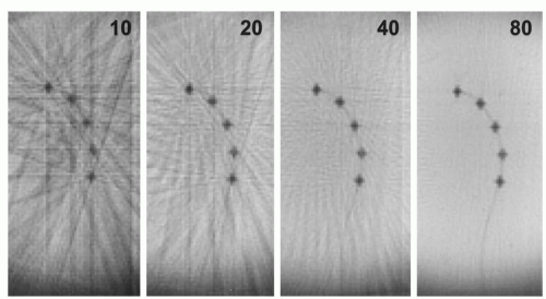 Figure 37.3. Images acquired with radial k-space filling of a catheter with dysprosium markers (see also Figure 37.7) in a water bath. The numbers in the images give the number of radials acquired to calculate the MR image, demonstrating how few radials are needed to depict the structure of the catheter markers. In addition, the effect of increasing the number of radials can be seen yielding a higher signal-to-noise ratio and diminishing streaking artifacts, which are caused by undersampling. |
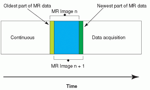 Figure 37.4. The sliding window reconstruction technique calculates images with a speed higher than the acquisition speed for a single image. This is achieved by using old and new data to calculate the next image. While this technique can, in principle, be applied to all k-space filling strategies, it is especially useful for radial scanning, because a single radial line acquires inner and outer parts of k-space adding fresh low- and high-frequency components to the newly calculated image. |
Parallel imaging techniques like SENSE and SMASH gained fast acceptance for clinical MR imaging. After incorporation of these techniques into interventional MR scanners, additional imaging speed will be available to further improve image quality (23).
Instrument Visualization
Despite the progress made in real-time imaging, the image quality of the different techniques is still poor compared to x-ray fluoroscopy. This becomes especially apparent, when a small catheter is to be visualized on an MR image acquired in real-time. Plastic catheters usually are black on MR images due to their lack of protons. Because of the smallness of interventional devices, they can only be seen if the spatial resolution of the MR image is high enough. In addition, the background has to be bright in order to provide a reasonable
contrast against the low signal intensity of instruments. So far, the spatial resolution and contrast characteristics of realtime imaging sequences are not sufficient to reliably depict an interventional instrument. Therefore, special means have been introduced to visualize devices. These are divided into passive and active techniques. Passive visualization is defined as direct visualization of the instrument in the acquired MR image. No changes are made on the side of the MR sequence or scanner hardware for passive visualization. Active visualization, on the other hand, requires special hardware and usually modifications of the MR imaging sequence in order to exploit the abilities of MR to localize a dedicated coil in 3D space. This information is used to actively project the position of this coil onto the MR image.
contrast against the low signal intensity of instruments. So far, the spatial resolution and contrast characteristics of realtime imaging sequences are not sufficient to reliably depict an interventional instrument. Therefore, special means have been introduced to visualize devices. These are divided into passive and active techniques. Passive visualization is defined as direct visualization of the instrument in the acquired MR image. No changes are made on the side of the MR sequence or scanner hardware for passive visualization. Active visualization, on the other hand, requires special hardware and usually modifications of the MR imaging sequence in order to exploit the abilities of MR to localize a dedicated coil in 3D space. This information is used to actively project the position of this coil onto the MR image.
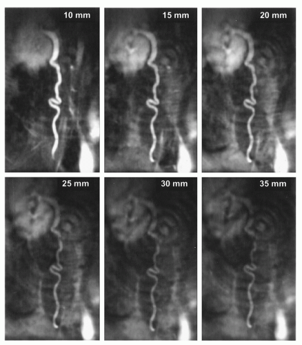 Figure 37.5. Images acquired with radial k-space filling and of increasing slice thickness are shown. The gadolinium-filled ureter simulates a vessel, which is filled with a blood pool agent, thereby constantly reducing the intraluminal T\. Despite the contrast agent, thicker slices yield a constantly diminishing contrast of the ureter against the background. The ring-like artifacts are due to the radial filling of k-space. |
Passive Visualization with Susceptibility Markers
In 1990, Rubin et al. found the artifact behavior of standard conventional radiographic catheters on MR images to be characterized by a small signal void, not allowing for reliable detection on the MR images. Therefore, they homogeneously doted polyethylene catheters with ferromagnetic material. Depending on the concentration of the ferromagnetic material a susceptibility artifact was caused, which exceeded the actual catheter size, thereby making the catheter easily visible on MR images (24). But the artifact behavior of those ferromagnetic catheters largely depends on their orientation to the main magnetic field B0. As this parameter cannot be controlled during angiography but is given by the vascular anatomy, those catheters are not well suited for MR interventions. The problem of dependency of susceptibility artifacts on the orientation to B0 was solved by Bakker et al. (25), who composed ring-like markers of dysprosium oxide around a catheter (Fig. 37.7). Dysprosium belongs to the group of lanthanides (rare earth metals) as does the well-known element gadolinium. High concentrations of lanthanides cause signal voids due to differences in the ability to become magnetized compared to the surrounding human tissue. This ability to become magnetized is called susceptibility and signal voids, which are due to
differences in the ability to become magnetized, are therefore termed susceptibility artifacts. The ability to reliably visualize these catheters was proven in vitro as well as in a human volunteer (26). While the dependency of susceptibility markers on the orientation to B0 was solved, the size of the marker in the MR image is still dependent on sequence parameters, the TE being the most important one. Considering the difficulty of real-time MR imaging, it is not desirable to have to adapt imaging parameters in order to optimally visualize interventional instruments. Furthermore, the tomographic nature of MRI means that a large signal void is advantageous as long as the instrument is located in a large vessel like the aorta. This will ensure that the device can be localized even if it is not positioned in the middle of the imaged slice. On the other hand, for smaller vessels large susceptibility artifacts will obscure the vascular anatomy (27). Many dedicated interventional scanners allow on-the-fly adaptation of sequence parameters, and thereby can at least somewhat influence the size of susceptibility markers, but considering reasonable TEs for real-time scanning the effect is relatively small (Fig. 37.8).
differences in the ability to become magnetized, are therefore termed susceptibility artifacts. The ability to reliably visualize these catheters was proven in vitro as well as in a human volunteer (26). While the dependency of susceptibility markers on the orientation to B0 was solved, the size of the marker in the MR image is still dependent on sequence parameters, the TE being the most important one. Considering the difficulty of real-time MR imaging, it is not desirable to have to adapt imaging parameters in order to optimally visualize interventional instruments. Furthermore, the tomographic nature of MRI means that a large signal void is advantageous as long as the instrument is located in a large vessel like the aorta. This will ensure that the device can be localized even if it is not positioned in the middle of the imaged slice. On the other hand, for smaller vessels large susceptibility artifacts will obscure the vascular anatomy (27). Many dedicated interventional scanners allow on-the-fly adaptation of sequence parameters, and thereby can at least somewhat influence the size of susceptibility markers, but considering reasonable TEs for real-time scanning the effect is relatively small (Fig. 37.8).
 Figure 37.6. Radial scanning of the iliac arteries demonstrates the intrinsic contrast of this gradient-echo technique. For the first image, arteries and veins are superimposed. The second image was acquired with a saturation band distally to the imaged area, resulting in a complete suppression of the venous signal, thereby allowing clear depiction of the iliac arteries. |
Passive Visualization with the Field Inhomogeneity Concept
In order to be able to change the size of an instrument in the MR image independently of the sequence parameters the field inhomogeneity concept was developed (28). A loop of insulated copper wire is wound around the instrument going from the hub to the tip and back (Fig. 37.7). A small energy source is connected to the copper wire loop to allow the flow of a small amount of direct current through the wire. According to the rule of thumb the flowing current creates a local magnetic field which causes a local field inhomogeneity and, thereby, a signal loss. Depending on the strength of the current, the artifact size can be varied (Fig. 37.9). The signal void can be shaped by different wire configurations. This allows the production of only local markers at the beginning and the end of a balloon or the marking of the whole catheter length. As with the passive method first proposed by Bakker, the wire can be wound in order to cause signal voids independent of the catheter orientation to B0 (29). The small currents of up to 150 mA—which were needed to produce sufficiently large areas of signal void during in vivo experiments (30)—are too small to be a safety problem, especially when the insulated copper wires can be positioned inside the catheter walls as it is done with standard braiding. Nonetheless, the wires can act as antennas and in case of resonance, they could heat up significantly (2). This safety aspect will be discussed in more detail in a separate section below.
The field inhomogeneity concept has been evaluated in animal experiments showing its advantage for the visualization of the interventional device in vessels of different size (Fig. 37.10) (31). Applying a current around 150 mA it was possible to constantly visualize a catheter over its full length in the aorta of a pig. As soon as the catheter was steered into the renal artery the signal void obscured the vascular anatomy. This could be simply changed by switching off the current, while the MR imaging sequence parameters were kept constant (17).
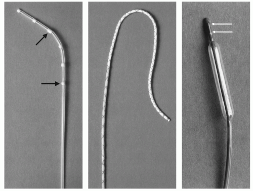 Figure 37.7. Passive visualization can be achieved by susceptibility markers (left image, arrows) or by the field inhomogeneity principle (middle image), where a copper wire is forming a loop along the catheter shaft. If wound like a double helix, as in this example, a small current sent through the insulated copper wire will cause a signal drop around the whole length of the catheter shaft. Active visualization needs a microcoil at the catheter tip to localize its position (right image, arrows). |
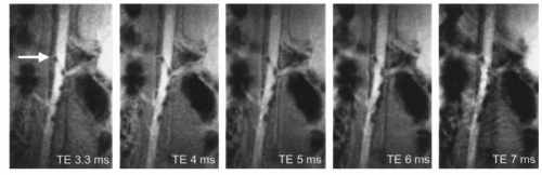 Figure 37.8. The size of passive susceptibility markers can be changed by modifying the echo time. Longer echo times yielding bigger signal voids around the markers, as can be seen on the radial gradient-echo images acquired with increasing TE. As the increase in echo time lengthens the image acquisition and degrades the image quality, there is a limit to the possibility of changing the effect of susceptibility markers. |
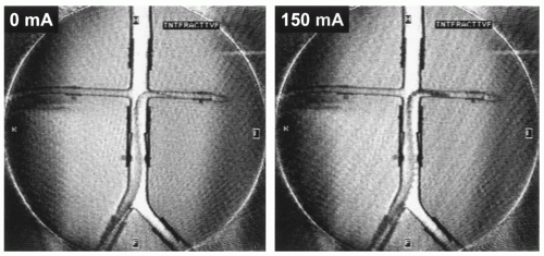 Figure 37.9. A catheter with the field inhomogeneity principle is imaged in a flow phantom by radial scanning. The artifact around the catheter can be increased by sending a current—in this example of 150 mA—through the copper wire running along the catheter shaft. |
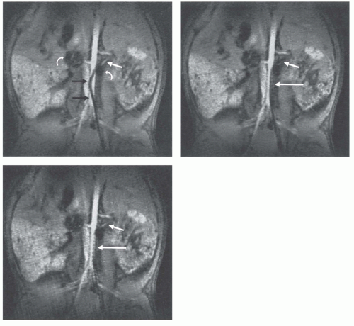 Figure 37.10. Real-time radial images of a field inhomogeneity catheter with current switched on (A,B) and off (C). While the catheter is positioned in the aorta the proximal part of the left renal artery can be depicted (A
Get Clinical Tree app for offline access
Stay updated, free articles. Join our Telegram channel
Full access? Get Clinical Tree


|