Potential sources of electromagnetic interference (EMI), often a concern for patients with cardiac devices, are often misdirected because of myth or hype by the media. It is important for the caregiver to know not only what sources of interference are of potential concern to patients with devices, but also how external interference actually affects pacemakers, implantable cardioverter-defibrillators (ICDs) and cardiac resynchronization therapy (CRT) systems. Interference refers to an inappropriate device response to electromagnetic signals resulting in absent, modified, or inappropriate detection or therapy.
Implantable devices are subject to interference from many sources. Most sources of EMI are nonbiologic but, in addition, biologic sources of interference, such as myopotentials, may cause pacemakers and defibrillators to malfunction. In general, contemporary devices are effectively shielded against commonly encountered EMI. There has always been some concern about EMI that patients may encounter in the nonhospital environment, but because of improvements in pulse generator shielding and design, EMI in the nonhospital environment is now of less concern, with the exception of some military and industrial environments. The principal sources of interference that affect pacemakers and defibrillators are in the hospital environment.
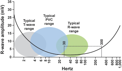
The portions of the electromagnetic spectrum that may affect implantable devices are radio waves, with frequencies between 0 and 109 Hz, including alternating current electricity supplies (50 or 60 Hz) and electrocautery, and microwaves, with frequencies between 109 and 1011 Hz1 (Fig. 12.1). Higher frequency portions of the spectrum, including infrared, visible light, ultraviolet, X-rays, and gamma rays, do not usually interfere with implanted devices because their wavelength is much shorter. However, therapeutic radiation can damage pulse generator circuitry directly.
Fig. 12.1 Electromagnetic frequency spectrum of intracardiac events. PVC, premature ventricular contraction. Potential sources of external interference often fall within the 30–300 Hz range.
EMI enters the device by conduction through body tissues if the patient is in direct contact with the source, or by radiation if the patient is in an electromagnetic field in which implanted device leads acts as an antenna or the telemetry antenna picks up the signal. Implantable devices have been protected from interference by shielding of the pacemaker circuitry, filtering of the incoming signal, and reduction of the distance between the electrodes to minimize the “antenna” size, thus maximizing nearby (myocardial) signals while minimizing far-field signals. Similarly, ICD systems utilizing true bipolar sensing (tip to ring) are less susceptible to EMI than those incorporating integrated sensing (tip to distal coil) right ventricular leads due to the smaller “antenna” with the tip to ring lead. The contemporary pulse generator is protected from most sources of interference because the circuitry is shielded inside a stainless steel or titanium case. In addition, body tissues provide some protection by reflection or absorption of external radiation.
Bipolar leads sense less conducted and radiated interference because the distance between anode and cathode is smaller than that for unipolar leads. Bipolar sensing configuration largely eliminates myopotential inhibition in pacemakers. Nonetheless, contemporary pacemakers with unipolar sensing configuration are not commonly affected by myopotential inhibition. In general, although older studies have shown that there is considerably less sensing of external electrical fields and less effect from electrocautery during surgery with bipolar sensing, most patients do well clinically with unipolar sensing configuration as well.
Defibrillators incorporate variable signal amplification to permit detection of fine ventricular fibrillation (VF) electrograms while avoiding sensing of T waves, so that myopotential interference may on occasion occur. Because amplification increases with time and is augmented following paced beats, oversensing is most likely to occur at slow heart rates, particularly while pacing.
Sensed interference is filtered by narrow band-pass filters to exclude noncardiac signals. However, signals in the 5–100 Hz range are not filtered because they overlap the cardiac signal range. These signals can result in abnormal pacemaker and ICD behavior if they are interpreted as intrinsic cardiac activity.
The possible responses to external interference include the following:
- Inappropriate inhibition of pacemaker output (Fig. 12.2)
- Inappropriate triggering of pacemaker output (Fig. 12.3) and inappropriate tracking (if sensed on the atrial channel)
- Asynchronous pacing (Fig. 12.4)
- Reprogramming, usually to a backup mode (Fig. 12.5)
- Inappropriate initiation of “other” features, such as mode switching or rate drop response (Fig. 12.6)
- Inappropriate detection of EMI as a ventricular tachyarrhythmia resulting in ICD discharge (Fig. 12.7)
- Inappropriate detection of EMI as an atrial tachyarrhythmia (Fig. 12.8)
- Failure to sense VT/VF.
Fig. 12.2 Electrocardiographic tracing from a patient with a pacemaker programmed to the VVI mode. Isometric maneuvers performed at a ventricular sensitivity of 1.4 mV result in myopotentials and pacemaker inhibition.
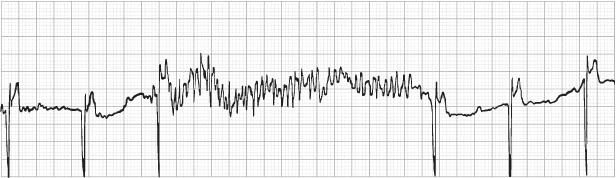
Fig. 12.3 Electrocardiographic recording taken at rest from a patient with a pacemaker programmed to the DDDR mode. During exposure to equipment emitting a radiofrequency signal close to that of the pacemaker, the external signal was sensed on the atrial sensing circuit of the pacemaker, resulting in tracking and a paced ventricular rate at the programmed upper rate limit.
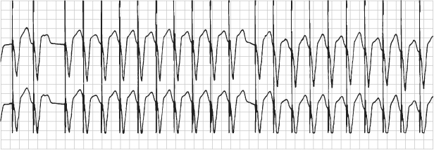
Fig. 12.4 Electrocardiographic recording taken at rest from a patient with a pacemaker programmed to the DDDR mode. During exposure to equipment emitting a radiofrequency signal close to that of the pacemaker, the external signal resulted in intermittent asynchronous (DOO) pacing.
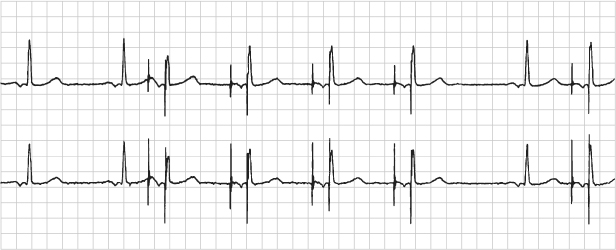
Fig. 12.5 Electromagnetic reprogramming. (A) Transtelephonic electrocardiographic tracing during magnetic application from a patient with a pacemaker programmed to the DDD pacing mode. The transmission reveals VOO pacing instead of the expected DOO response. (B) Electrocardiographic tracing obtained after reprogramming during magnetic application to the DDD mode; there is appropriate DOO pacing. A history obtained from the patient revealed that she had undergone magnetic resonance imaging of her head and not notified the caregiver that she had a pacemaker.
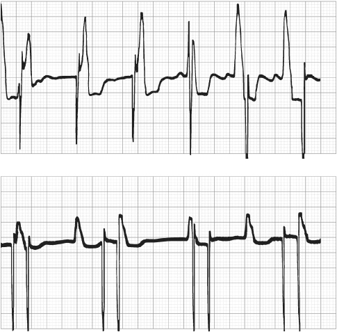
Fig. 12.6 Electrocardiographic tracing from a patient with a dual-chamber pacemaker. The electrocardiogram is obtained during exposure to a source of electromagnetic interference. The interference is sensed on the atrial sensing channel, and the pacemaker responds by rapid ventricular tracking. Criteria are met for mode switching, and the rate begins to fall back to the programmed lower rate.
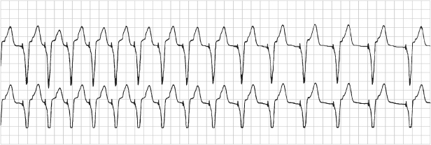
Fig. 12.7 ICD discharge as a result of EMI. (Top: atrial tip to ring EGM; middle: ventricular tip to ring EGM; bottom: marker channel.)
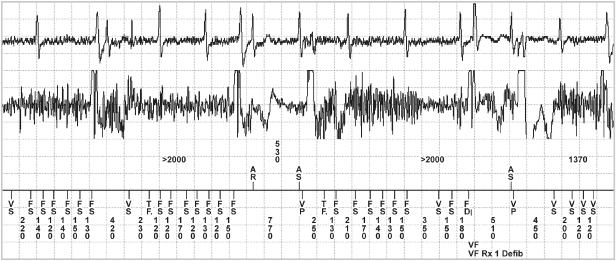
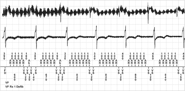
Fig. 12.8 Noise caused by electrical stimulation delivered during use of some type of chiropractic treatment equipment. The noise was sensed on both channels but more so on the atrial channel of the device. (Top: atrial tip to ring EGM; middle: ventricular tip to ring EGM; bottom: marker channel.)
The most common responses to EMI are triggering or inhibition of pacemaker function, and false tachyarrhythmia detection in ICDs.
Pacemaker Responses to Noise
Asynchronous Pacing
To protect the patient from inappropriate inhibition of pacemaker output, pacemakers have the capability of reverting to asynchronous pacing if exposed to sufficient interference. This change is usually activated by signals detected during a noise-sampling period within the pacemaker timing cycle (Fig. 12.9). The NSP (noise-sampling period or resettable refractory period) occurs immediately after the ventricular refractory period (VRP), which follows a ventricular sensed or paced event. During the VRP the ventricular sensing channel does not react to any signals and in particular prevents oversensing of the afterpotential of the ventricular pacing artifact or the evoked QRS and T waves. The VRP usually lasts between 200 and 400 ms, and events occurring during this period have no effect on pacemaker timing. The NSP lasts between 50 and 200 ms. If an event is sensed during this period, it is interpreted as noise, and either the VRP or the NSP is restarted. In addition, in a dual-chamber mode, the post-ventricular atrial refractory period and the upper rate interval, but not the lower rate interval, are restarted. If a further noise event is detected in the NSP, the VRP or NSP again is restarted and the pacemaker does not recognize cardiac signals. Repetitive noise events eventually cause the lower rate interval to time out, and a pacing pulse is delivered. Continuous noise thus results in asynchronous pacing at the lower rate limit.
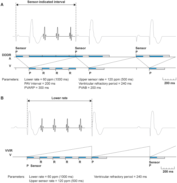
Fig. 12.9 (A) Examples of noise reversion mechanisms from one manufacturer. Noise reversion occurs in a dual-chamber pacemaker when there is continuous refractory sensing in the atrial or ventricular refractory period. During noise reversion a pacemaker in a non-rate-adaptive mode, pacing will occur at the programmed lower rate. If the pacemaker is programmed to most rate-response modes, pacing will occur at the sensor-indicated rate. (B) Although there will be some variation among manufacturers, in the VVIR mode the pacemaker will most likely pace at the programmed lower rate during noise reversion. P, paced atrial or ventricular event; R, intrinsic ventricular event; PVAB, post-ventricular atrial blanking; PVARP, post-ventricular atrial refractory period.
(Reproduced with permission from Medtronic Adapta technical manual, pp. 3–28.)
In some pacemakers, rather than timing out the lower rate interval, repetitive detection of noise in the NSP causes temporary switching to a specific “noise reversion mode,” which is usually an asynchronous mode (VOO or DOO). In some pacemakers with programmable polarity, the pacing output is unipolar in the noise reversion mode, even if the device is programmed to bipolar pacing configuration.
In other devices there is technically not a noise reversion mode but designated operation during “noise detection.” For example, Fig. 12.10 depicts operation for a device in which sensing an intrinsic depolarization begins a 60-ms noise rejection interval which is retriggered in the presence of noise. Intrinsic events will not be detected during noise rejection, so that asynchronous operation results during ongoing noise sensing.
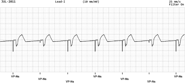
Fig. 12.10 Electrocardiographic example with ventricular pacing (VP) with noise sensing (NS). In this example from a Boston Scientific pacemaker, a paced event initiates a 50-ms fixed noise rejection period. If there is continued noise detected a 60-ms retriggerable noise rejection interval is initiated.
Whether noise causes inhibition or asynchronous pacing depends on the duration and field strength, and frequency of the signal. As the field strength increases, there is a greater tendency towards asynchronous pacing. At low field strengths the noise may be sensed only intermittently and thus may not be detected in the NSP, but rather in the “alert” period between the NSP and the next pacing pulse, leading to inhibition. At higher field strengths, the noise is more likely to be sensed continuously, with sensing during the NSP resulting in asynchronous pacing. Pacemaker models vary considerably in their susceptibility to noise.
Because VT/VF can be a high-frequency low-amplitude signal, ICDs necessarily interpret some noise episodes as VF. ICDs either have no noise reversion mode or very short noise sampling windows, providing imperfect protection from exogenous interference. If the noise is sufficiently sustained, VT/VF is detected and therapies delivered. Nonetheless, due to the filtering and insulation utilized by ICDs, the real-world percentage of shocks caused by EMI is under 3%.2
Mode Resetting (Power-On Reset, or Electrical Reset)
Transient EMI of sufficient strength can reprogram the pacing mode, as opposed to temporarily modifying function. This is most commonly caused by external defibrillation or electrocautery, and occasionally by exposure to magnetic resonance imaging (MRI) magnets, and, in contrast to noise reversion, pacing inhibition, or inappropriate shock, does not resolve when the EMI is discontinued. Following powerful EMI the device usually reverts to the “backup mode” or “reset mode,” which in pacemakers is often the same as the pacemaker elective replacement indicator or “battery depletion” mode (Fig. 12.5). Confusion can arise when the “backup mode” and the default settings at battery depletion are the same. Reversion to these parameters indicates that either the pacemaker has been affected by interference or has truly reached battery depletion. In both cases, careful attention to the programmer telemetry, when available, is helpful. If the telemetered battery impedance remains low and the battery voltage is normal, the pacemaker battery is not exhausted and interference is the likely cause of the parameter change. If the etiology of revision to the “backup” mode remains unclear, reprogramming to the preset pacing mode but with maximum output and an increased rate will usually quickly result in reversion to battery depletion settings if the pacemaker battery is truly near end of life.
The backup or reset mode is usually VVI, and if the pulse generator has programmable polarity, the backup polarity is usually unipolar. Some pacemakers may reset to the VOO mode if subjected to interference, potentially resulting in competition with the intrinsic rhythm.
In some ICDs an electrical reset will result in an alert to indicate that the device has been reset and may require reprogramming. Some devices may have both a full “reset,” i.e., programmed parameters are reset to default values, and a partial reset which may not affect programmed parameters. If a device reverts to default values, such values provide basic device functionality and are considered safe for the majority of patients. Reset varies among manufacturers and the technical manual and/or manufacturer’s technical service group should be contacted if there is any question about device behavior with electrical reset. In ICDs, a power-on reset will usually cause the device to revert to a backup pacing mode (such as VVI at 60 ppm) and “shock only” therapies with maximum energy shocks for heart rates greater than predefined detection rates, typically >140–170 ppm. This occurs because only factory preset parameters stored in nonvolatile memory are available following the power-on reset. However, terminology may be confusing. The term “Power on Reset” (POR) is used by several manufacturers to indicate a form of device reset that may occur when the voltage drops extremely low. When the device experiences a POR, backup defibrillation therapy is not available.
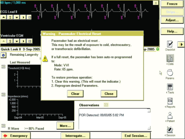
Exposure to low temperatures before implantation may result in mode resetting. The cold temperatures cause an increase in the internal battery resistance, and the subsequent decrease in the battery voltage causes the end-of-life indicator or reset mode to be activated. Because this effect occurs frequently during shipment in cold climates, all pacemakers should be routinely interrogated before implantation and reprogrammed if necessary (Fig. 12.11). If an ICD interrogation before surgical implantation indicates that an electrical reset has occurred, it is best to contact the manufacturer before implanting the pulse generator.
Environmental Electromagnetic Interference
Electric and magnetic signals are emitted by industrial, hospital medical, and domestic sources. Each of these environments is discussed individually.
Hospital Environment
The hospital is the most common environment with sources of potential EMI that can cause significant interference with implantable cardiac devices (Table 12.1).
Table 12.1 Sources of electromagnetic interference in the hospital.
|
Electrocautery
Electrocautery continues to be one of the most common potential sources of EMI for patients with implanted devices. Electrocautery involves the use of radiofrequency current to cut or coagulate tissues. It is usually applied in a unipolar fashion between the cauterizing instrument (the cathode) and the indifferent plate (the anode) attached at a distance to the patient’s skin. Bipolar cautery equipment is also available. The frequency is usually between 300 and 500 kHz (at frequencies of <200 kHz muscle and nerve stimulation may occur). Cutting diathermy uses a modulated signal, so that bursts of energy are applied, whereas coagulation diathermy uses an unmodulated signal to heat the tissue. Radiofrequency ablation of cardiac tissue for the treatment of arrhythmias is delivered most commonly via intracardiac unipolar electrodes at a frequency around 500 kHz, although some newer systems also use bipolar delivery between intracardiac electrodes, for a shallower lesion.
The electrocautery current a pacemaker or ICD receives is related to the distance and orientation of the cautery electrodes relative to the pacemaker and lead. High current is generated if the cautery cathode is close to the pacemaker, or if the cautery electrode and return patch surround the pacemaker.
Electrocautery can result in multiple clinical responses from an implanted pulse generator (Table 12.2). The electrocautery signal may induce currents in the pacing lead and cause local heating at the electrode–tissue interface, leading to myocardial damage with a subsequent increase in the pacing and/or sensing threshold. Threshold alteration is usually transient.
Table 12.2 Potential effects of electrocautery.
|
To prevent inappropriate pacemaker inhibition during cautery, a magnet may be applied over the pacemaker to convert it to an asynchronous mode. Although this maneuver may be successful, it may open some pacemakers to reprogramming by the electrocautery signal and is therefore controversial.
Pacemakers with rate-responsive functions may exhibit inappropriate responses during surgery due to vibration caused by other intraoperative equipment or by the surgical procedure. The electrocautery signal may overwhelm the impedance measuring circuit of a minute ventilation rate-responsive pacemaker leading to pacing at the upper rate limit.
In ICDs, electrocautery signals may be misidentified as cardiac activity, resulting in inappropriate delivery of antitachycardia pacing or defibrillation or in failure to detect VF. For these reasons, the ICD patient should be placed on a monitor and therapies turned “off” prior to the surgical procedure. Personnel capable of recognizing tachyarrhythmias and responding to the rhythm abnormalities with external defibrillation should be available throughout the time that therapies are turned off.
If the ICD patient is pacemaker-dependent, it is important to know the ICD response to magnet application. Magnet response varies between manufacturers and sometimes between models of the same manufacturer (Table 12.3). Most commonly, but certainly not universally, magnet applications in ICDs disables tachyarrhythmia detection without altering pacing function. In this situation, it is best to use a programmer to confirm device function before dismissing the patient from monitored care. The caregiver also needs to know whether the ICD has a programmable asynchronous mode (Table 12.4). Management of the pacing function of an ICD is particularly important at the time of surgery in order to avoid electrocautery-induced inhibition in the pacemaker-dependent patient. Many ICDs have a specific electrocautery protection mode design to be programmed on during surgery. In this mode, pacing is asynchronous and tachyarrhythmia detection is disabled.
Table 12.3 ICD magnet response.
| Medtronic | Pacing mode, pacing rate and interval as programmed. VF, FT and VFT detection is suspended. Patient Alert audible tones will occur if applicable and enabled |
| Boston Scientific | If “ENABLE MAGNET USE” is “on” (nominal), device will emit beeping synchronous tones on the R wave. If after 30 s the beeping does not change to a continuous tone, the magnet must be taped over the device to temporarily inhibit therapy. If beeping changes to a continuous tone after 30 s, tachy mode has gone to “off” and magnet can be removed. To turn device back to Monitor and Therapy, magnet should be placed back over the device for 30 s until R-wave synchronous tones are heard. Magnet application does not affect pacing mode/rate. If “ENABLE MAGNET USE” is programmed “off” (nominally “on”), then a magnet will not inhibit therapy. No tones will be emitted and a programmer will be needed to turn device off |
| SJM | Two programmable options for magnet response: NORMAL (Nominal) or IGNORE. In “NORMAL” response – when magnet is placed over the ICD it blinds detection and delivery of therapy. Bradycardia pacing is not affected by a magnet placed over the device and must be reprogrammed if asynchronous pacing is needed. If “IGNORE” is programmed the blinding is null and void |
| Sorin/ELA | When magnet is applied it disables tachy therapy and arrhythmia detection. Brady function is to pace in the programmed mode at the magnet rate (corresponding to battery voltage); pacing outputs are set to maximum; rate hysteresis and AV extension are set to zero; AV delay is set to the programmed AV delay at rest |
| Biotronik | When a magnet is applied, tachyarrhythmia therapy and detection will be suspended and rate-response is suspended |
Table 12.4 ICD asynchronous mode availability.
|


