Electrocardiography

4 Electrocardiography


It is now more than 100 years since the Dutch physiologist Willem Einthoven recorded the first ECG from humans. Although the number of recording leads has increased from 3 to at least 12 and the recording instruments have evolved into sophisticated automated digital recorders capable of recording, measuring, and interpreting the electrocardiographic waveform, the basic principles underlying the ECG are unchanged. The electrocardiograph is basically a voltmeter that records, from the body surface, the uncanceled voltage gradients created as myocardial cells sequentially depolarize and repolarize.


The ECG is the most commonly used technique to detect and diagnose heart disease and to monitor therapies that influence the heart’s electrical activity. It is noninvasive, virtually risk free, and relatively inexpensive. Since its introduction, a large database has been assembled correlating the ECG waveform recorded from the body surface to the underlying electrical activity of individual cardiac cells on the one hand, and to the clinical presentation of the patient on the other, thereby providing insight into the electrical behavior of the heart and its modification by physiologic, pharmacologic, and pathologic events.


Leads


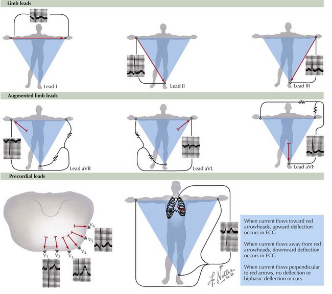
Twelve leads are routinely used to record the body surface ECG: three bipolar limb leads labeled I, II, and III; three augmented limb leads labeled aVR, aVL, and aVF; and six unipolar chest leads labeled V1 through V6 (Fig. 4-1). In the bipolar limb leads, the negative pole for each of the leads is different, whereas in the unipolar chest leads, the negative pole is constant and created by the three limb leads. This is referred to as Wilson’s central terminal. The positive chest lead is, in effect, an exploring lead that can be placed anywhere. In children, the routine ECG often includes leads placed on the right side of the chest in positions referred to as V3R and V4R. Similar right-sided chest leads are often used in adults to diagnose right ventricular infarction, and one or more leads placed on the back are sometimes used to diagnose posterior wall infarction.


The chest leads are relatively close to the heart and are influenced by the electrical activity directly under the recording electrode. This is in contrast to the limb leads in which the electrodes are placed outside of the body torso. Changes in the position of an individual chest lead or the relationship between the chest leads and the heart may cause significant changes in the ECG pattern. For instance, if the patient is in a sitting rather than a supine position, the relationship of the various chest leads to the heart will change and the ECG waveform recorded by the chest leads may be altered. Similarly, if a chest lead is placed an interspace too high or too low, the ECG waveform recorded by that lead will change. For this reason, when serial ECGs are recorded, it is important that lead placement be consistent and reproducible. In contrast, limb leads may be placed anywhere on the various limbs with little significant alteration of the ECG waveform. However, when they are placed within the body torso, as is the case during exercise testing and when patients are monitored in critical care areas, the waveform recorded by the limb leads will be affected.


Electrocardiographic Waveform


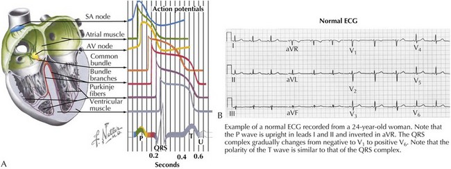
The ECG waveform consists of a P wave, a PR interval, the QRS complex, an ST segment, and T and U waves. The relationship of these waveform components to the underlying action potentials of the various cardiac tissues is shown in Figure 4-2A, as is an example of a normal 12-lead ECG in Figure 4-2B. The P wave reflects depolarization of the atria, the QRS complex reflects depolarization of the ventricles, and the ST segment and T wave reflect repolarization of the ventricles. The U wave occurs after the T wave and is thought to be an electromechanical event coupled to ventricular relaxation.


Depolarization of the sinus node occurs before the onset of the P wave, but its voltage signal is too small to be recorded on the body surface by clinically used electrocardiographic machines and the event is electrocardiographically silent. Similarly, the electrical activity of the atrioventricular (AV) junction and the His-Purkinje system, which occur during the PR interval, is electrocardiographically silent.


P Wave


The P wave is caused by the voltage gradients created as the atrial cells sequentially depolarize. The shape and duration of the P wave are determined by the sequence of atrial depolarization and the time required to depolarize the cells of both atria. The sinus node is located at the junction of the superior vena cava and the right atrium, and the direction of atrial depolarization, from right to left, from superior to inferior, and from anterior to posterior reflects this geography. This results in a P wave that is characteristically upright or positive in leads I, II, V5, and V6 and inverted or negative in lead aVR. In lead V1, the P wave may be upright, biphasic, or inverted. The amplitude and duration of the normal sinus P wave may be affected by atrial hypertrophy and dilation and by slowing of interatrial and intra-atrial conduction.


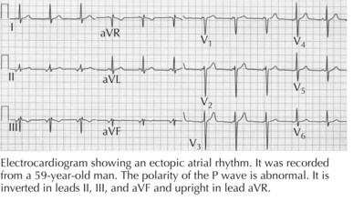
Impulses arising from an ectopic atrial focus are associated with P waves whose shape depends on the location of the focus. If the abnormal focus is in close proximity to the sinus node, the sequence of atrial activation will be normal or nearly normal, and the P wave will resemble the normal sinus P wave. The more distant the ectopic focus is from the sinus node, the more abnormal will be the sequence of atrial activation and the P-wave configuration. For instance, impulses originating in the inferior portion of the atrium or within the AV node will depolarize the atria in a retrograde, superiorly oriented direction and will be associated with the P waves that are inverted in leads II, III, and aVF and upright in lead aVR (Fig. 4-3).


QRS Complex


The QRS complex reflects ventricular depolarization. The interventricular septum is the first portion of the ventricle to be depolarized. Thereafter, the impulse spreads through the His-Purkinje system and then depolarizes the ventricles simultaneously, from apex to base and from endocardium to epicardium. Because the left ventricle is three times the size of the right, its depolarization overshadows and largely obscures right ventricular depolarization. The QRS complex reflects this left ventricular dominance, and for this reason, the QRS complex is usually upright or positive in leads I, V5, and V6, the left-sided and more posterior leads, and negative or inverted in aVR and V1, the right-sided and more anterior leads. It is only in situations such as right bundle branch block and significant right ventricular hypertrophy that the electrical activity associated with right ventricular depolarization is identified on the ECG.


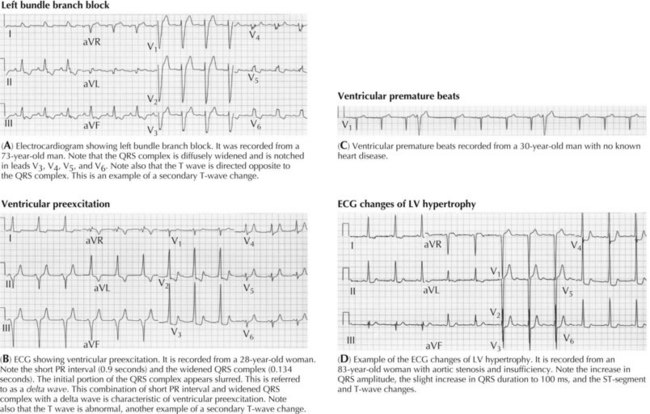
The QRS complex is altered in both shape and duration by abnormalities in the sequence of ventricular activation. These include the bundle branch blocks (Fig. 4-4A), the fascicular blocks, ventricular preexcitation (Fig. 4-4B), nonspecific intraventricular conduction disturbances, and ectopic ventricular beats (Fig. 4-4C). The increase in QRS duration may range from a few milliseconds, as in the case of fascicular blocks, to more than 40 milliseconds, as with bundle branch blocks. The fascicular blocks reflect conduction slowing in one fascicle of the left bundle and are characterized by a shift in electrical axis and subtle changes in the initial portion of the QRS complex. The bundle branch blocks are caused by conduction slowing or block in the right or left bundle branch, usually caused by fibrosis, calcification, or congenital abnormalities involving the conducting system. They are associated with more pronounced abnormalities in the sequence of ventricular activation than are the fascicular blocks and thus with more significant changes in the QRS configuration. Intraventricular conduction abnormalities may also occur without a change in QRS configuration and reflect slow conduction without a change in the sequence of activation. Such slowing may be caused by cardioactive drugs, an increase in extracellular potassium concentration, and diffuse fibrosis or scarring as may occur in patients with severe cardiomyopathies.


The electrocardiographic criteria for the diagnosis of intraventricular conduction disturbances have been published. Important features include the following:


Stay updated, free articles. Join our Telegram channel

Jun 12, 2016 | Posted by in CARDIOLOGY | Comments Off on Electrocardiography

Full access? Get Clinical Tree

Get Clinical Tree app for offline access