Chapter 7 Echocardiography
Echocardiography, particularly transesophageal echocardiography (TEE), is an important diagnostic tool in the cardiothoracic intensive care unit (ICU), and it has a broad range of indications (Table 7-1).1 Echocardiography is essential in the assessment of complex hemodynamic instability,2 in the evaluation of suspected endocarditis,3 and to guide cardioversion in patients with atrial fibrillation of more than 2 days’ duration.4 In hemodynamically unstable cardiac surgery patients, TEE reliably identifies the cause of the hypotension, often revealing problems that are unsuspected on the basis of the hemodynamic parameters.5
Table 7-1 Indications for Echocardiography in the ICU
| Assessment of hemodynamic instability |
| Assessment of unexplained respiratory failure |
| Suspected endocarditis |
| Suspected pulmonary embolus |
| Suspected aortic dissection |
| Investigation of a source of embolus |
| Positioning of an intraaortic balloon pump (IABP) or cannulas for mechanical cardiac support |
| Prior to cardioversion in patients with atrial fibrillation of more than 2 days’ duration (TEE only) |
The echocardiographic findings for specific conditions are dealt with in the appropriate sections of the book. In this chapter, the principles, imaging modes, and methods of assessment of cardiac function are reviewed. (Much of the information provided in this chapter is drawn from the short textbook Practical Perioperative Transesophageal Echocardiography.6)
ULTRASOUND MODALITIES
M-mode Imaging
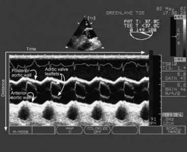
M-mode imaging displays reflected ultrasound waves along a single scan line over time (Fig. 7-1). M-mode imaging has very high depth resolution and is therefore ideal for measuring distances along the scan line (e.g., ventricular wall thickness) and for observing rapidly moving structures (e.g., the motion of the aortic valve).
Doppler Imaging
Spectral Doppler
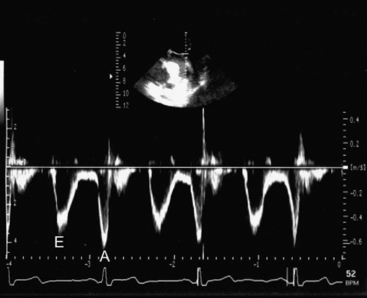
PW (Fig. 7-2) and CW Doppler (Fig. 7-3) display the velocity of blood along a single scan line over time so are therefore analogous to M-mode imaging. PW Doppler displays the velocity at a specific depth along the scan line (at the level of the operator-adjusted sample volume), whereas CW Doppler records velocities at all depths along the scan line. With appropriate machine settings, CW Doppler can record very high velocities (in excess of 5 m/sec), such as those that occur with mitral regurgitation, without aliasing. In contrast, with PW Doppler the Nyquist limit is typically less than 1.5 m/sec. However, PW Doppler has the advantage of being able to define the velocity at a particular depth. Velocity data obtained from CW and PW Doppler imaging can be used for quantitative measurements of flow and pressure. Tissue Doppler imaging is a modification of PW Doppler in which the velocity of solid tissue is displayed. Motion of the mitral annulus obtained with tissue Doppler imaging can be used to assess diastolic left ventricular function (see later material).
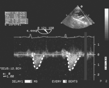
Figure 7.3 CW Doppler imaging. Time is displayed on the horizontal axis and velocity on the vertical axis. In this example, the PW Doppler beam has been directed through the LVOT and shows the velocities all along the scan line throughout the cardiac cycle. Thus, with CW Doppler the velocity profile has a “filled-in” appearance, compared with the “thin line” obtained with PW Doppler (compare this figure with Fig. 7-2). No flow is seen in diastole, indicating the absence of aortic regurgitation. Flow in systole represents left ventricular stroke volume. The outline of the velocity waveform has been traced to provide the VTI. In this example the VTILVOT is 26.5 cm which, assuming an LVOT area of 3.5 cm2, indicates a stroke volume of about 90 ml (see Equation 7-1 and text for details).
(Modified, with permission, from Sidebotham D, Merry A, Legget M: Practical Perioperative Transoesophageal Echocardiography. Fig. 4.27, p. 64. Philadelphia, Butterworth Heinemann, 2003.)
When using spectral Doppler to measure velocity, it is important that the direction of the Doppler beam and the blood flow (or tissue motion) be similar; failure to achieve this similarity results in an underestimation of the blood velocity. As a rule of thumb, if the blood and the Doppler beam are within 20 degrees of each other, the underestimation of velocity is negligible (<6%).
Estimating Flow From Velocity
where VTI is the velocity time integral, the area bounded by the Doppler velocity time curve over one cardiac cycle (see Fig. 7-3). This equation can also be used to estimate valve area, as described later.
STANDARD VIEWS
With TTE, imaging is limited by the ribs and sternum and by the proximity of the heart to the surface of the chest wall. With TEE, imaging is limited by the relationship of the esophagus and stomach to the heart and by the interposition of the airways between the esophagus and the great vessels. Thus, for each modality there are limited ranges of scanning planes from which a broad range of standard views can be obtained. For each standard transthoracic view there is usually an analogous transesophageal view.
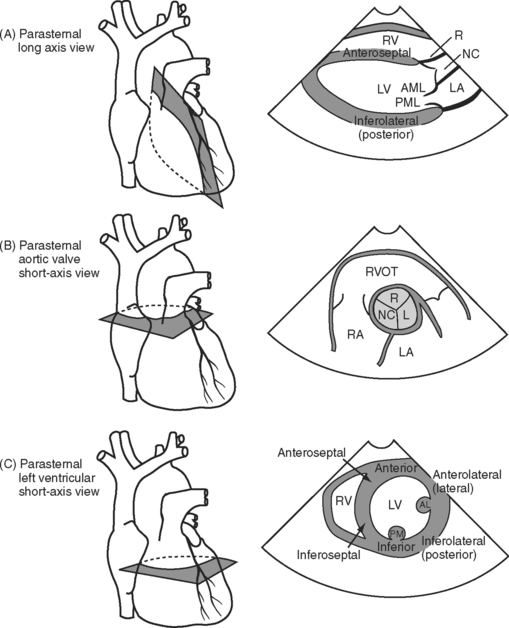
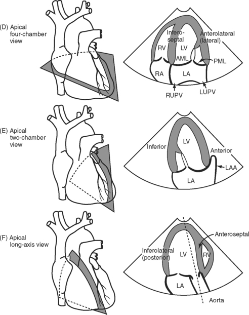
Three important TTE scanning planes are the parasternal, apical, and subcostal windows (Fig. 7-4). For parasternal imaging, the patient should be in the left lateral decubitus position and the transducer placed in the third, fourth, or fifth intercostal space, just to the left of the sternum, depending on which view is sought. For apical imaging, the patient should also be in the left lateral decubitus position and the transducer should be placed over the apical impulse (usually the fifth intercostal space, midaxillary line). For subcostal imaging, the patient should be supine, with the transducer positioned to the left of the xiphoid process. Bending the patient’s knees may relax the abdominal muscles and improve imaging. Subcostal imaging may provide superior views to parasternal and apical imaging in ventilated patients, and it has the advantage of not requiring the respositioning of the patient. In all scanning planes, changing the position, angulation, or rotation of the transducer alters the image plane.
With TEE, two important scanning planes are the midesophageal window (tip of transducer 30 to 40 cm from the lips) and the transgastric window (tip of transducer 40 to 50 cm from the lips) (Fig. 7-5). The image is adjusted by manipulating the tip of the TEE transducer. These manipulations involve flexing and retroflexing the tip of the probe, advancing and withdrawing the probe, and rotating the orientation of the sector scan between the horizontal (0 degrees), vertical (90 degrees), and reverse horizontal (180 degrees) imaging planes.
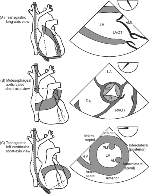
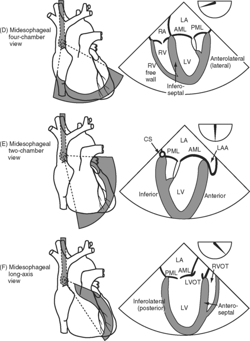
Figure 7.5 A-F, Selected transesophageal views. The views shown are analogous to the transthoracic views shown in Fig. 7-4A-F. The rotation of the sector scan between 0 degrees and 180 degrees is shown in the top right of each image. AL, anterolateral papillary muscle; AML, anterior mitral leaflet; CS, coronary sinus; L, left coronary cusp; LA, left atrium; LAA, left atrial appendage; LV, left ventricle; LVOT, left ventricular outflow tract; PM, posteromedial; RVOT, right ventricular outflow tract.
ASSESSMENT OF SYSTOLIC LEFT VENTRICULAR FUNCTION
Echocardiographic evaluation of left ventricular function should include assessment of ventricular dimensions, wall thickness, volume status, and systolic and regional function.
Ventricular Dimensions and Preload
Left ventricular chamber size depends on systolic function, diastolic function, and preload. Left ventricular diameter may be evaluated rapidly in a short-axis view (see Figs. 7-4C and 7-5C) with 2D or M-mode imaging. In patients with chronic volume overload, end-systolic and end-diastolic diameters can be used to guide the timing of surgery for patients with mitral and aortic regurgitation.
End-diastolic area (EDA) obtained from a left ventricular short-axis view (see Figs. 7-4C and 7-5C) is a surrogate for end-diastolic volume (EDV) and can therefore be used as a guide to preload. However, because EDA and EDV are dependent on ventricular function, changes in these parameters are more useful than absolute values. There is no threshold value for EDA that predicts fluid responsiveness.7 In patients with normal ventricular function who are euvolemic, EDA is normally 8 to 12 cm2 (excluding the papillary muscles from the trace). However, in patients with chronic left ventricular dilatation, a much higher EDA may be required to optimize preload. In contrast, a patient with severe diastolic dysfunction may develop pulmonary edema at a much lower EDA. The echocardiographic findings in hypovolemia are discussed in Chapter 20.
Stay updated, free articles. Join our Telegram channel

Full access? Get Clinical Tree


