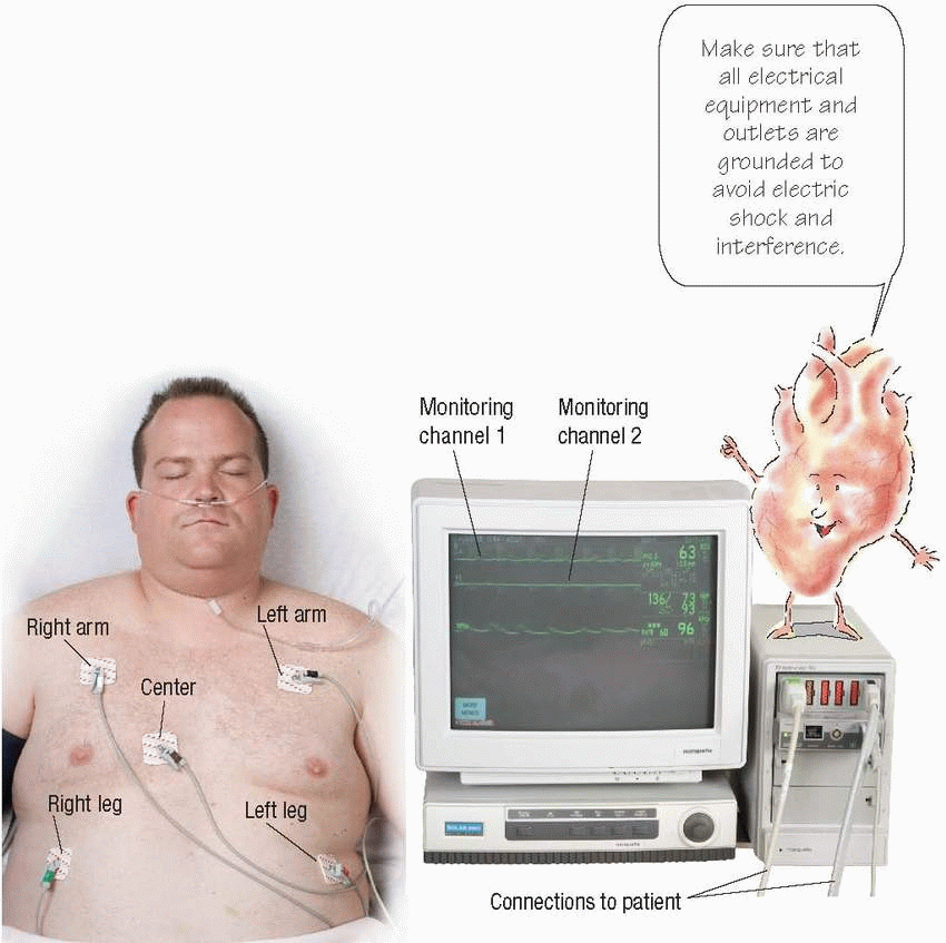
Cardiac monitoring
Electrocardiography is used to diagnose and monitor cardiac disorders. When a patient is hospitalzed, the first step is to begin continuous cardiac monitoring. In a hardwire system, the patient is connected directly to an electrocardiograph (ECG) by electrodes, leadwires, and a monitor cable. Most monitoring systems use three or five leads and provide a continuous readout of one or more leads simultaneously. Lead selection is based on the patient’s clinical situation. Lead V1 or V6 and an appropriate limb lead are usually used.
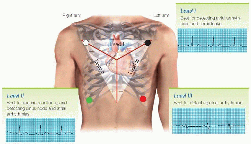
Leading leads
These illustrations show the heart views obtained by various leads as well as the best uses for each lead. Current moving from negative to positive gives an upward deflection of the complexes on the ECG; current moving from positive to negative gives a downward deflection.
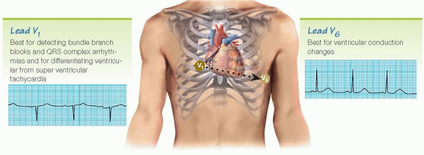
Viewing V6 requires moving the chest lead from the V1 precordial position to the V6 precordial position.
Troubleshooting monitor problems
What you see |
What might cause it |
What to do about it |
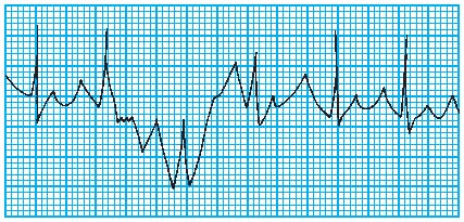
Artifact (waveform interference)
|
Seizures |
If the patient is having a seizure, notify the doctor and intervene as ordered. |
Chills |
Keep the patient warm. |
Anxiety |
Encourage the patient to relax. |
Improper electrode application |
Check the electrodes and reapply them if needed. Clean the skin well. |
|
Check the electrode gel. If the gel is dry, apply new electrodes. |
Short circuit in leadwires or cable |
Replace broken equipment. |
Electrical interference from other electrical equipment in the room |
Make sure all electrical equipment is attached to a common ground. |
Notify the biomedical department. |
False high-rate alarm
|
Gain setting too high, particularly with MCL1 setting |
Assess the patient for signs and symptoms of hyperkalemia. |
Decrease gain. |
Weak signals
|
Improper electrode application |
Reapply the electrodes. |
QRS complex too small to register |
Reset gain so that the height of the complex is greater than 1 mV. |
Try monitoring the patient on another lead. |
Wire or cable failure |
Replace any faulty wires or cables. |
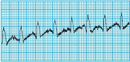
Wandering baseline
|
Patient restlessness |
Encourage the patient to relax. |
Improper electrode application; electrode positioned over bone |
Reposition improperly placed electrodes. |
Fuzzy baseline (electrical interference)
|
Electrical interference from other equipment in the room |
Ensure that all electrical equipment is attached to a common ground. |
Improper grounding of the patient’s bed |
Ensure that the bed ground is attached to the room’s common ground. |
Electrode malfunction |
Replace the electrodes. |
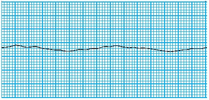
Baseline (no waveform)
|
Improper electrode placement |
Reposition improperly placed electrodes. |
Disconnected electrode |
Check if electrodes are disconnected. Reapply them as necessary. |
Dry electrode gel |
Check electrode gel. If the gel is dry, apply new electrodes. |
Wire or cable failure |
Replace faulty wires or cables. |
|
Rhythm strips
In electrocardiography, the electrical activity of the heart is displayed on a monitoring screen and can be printed onto a rhythm strip.
Worth the paper it’s printed on
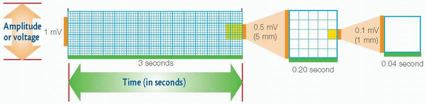
ECG paper consists of horizontal and vertical lines that form a grid. The top of the ECG paper has timing marks that represent 3-second intervals.
Vertical axis
The vertical axis measures amplitude in millimeters (mm) or electrical voltage in millivolts (mV). To determine the amplitude of a wave, segment, or interval, count the number of small blocks from the baseline to the highest or lowest point of the wave, segment, or interval.
Horizontal axis
The horizontal axis of the ECG strip represents time. When measuring or calculating a patient’s heart rate, a 6-second strip consisting of 30 large blocks is usually used (a 3-second strip is shown above).
8-step method
1 Evaluate atrial and ventricular rhythms
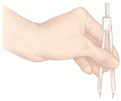
For the atrial rhythm, use a pair of calipers to measure the interval between P waves (P-P interval) in several ECG cycles. Set the calipers at the same point—at the beginning of the wave or on its peak. The P wave should occur at regular intervals, with only small variations associated with respiration.
To check the ventricular rhythm, use calipers to measure the R-R intervals. Remember to place the calipers on the same point of the QRS complex. If the R-R intervals remain consistent, the ventricular rhythm is regular.
2 Determine atrial and ventricular rates
To determine the atrial rate when the heart rate is regular, count the number small squares between identical points on two consecutive P waves, and then divide 1,500 by that number. To determine the ventricular rate, use the same method with two consecutive R waves.
3 Evaluate the P wave
Observe the P wave’s size, shape, and location in the waveform. If each QRS complex has a P wave, the sinoatrial (SA) node is initiating the electrical impulse, as it should be.
When using calipers to evaluate atrial rhythm, don’t lift the calipers. Instead, rotate one of its legs to the next P wave to ensure accurate measurements.
4 Calculate the PR interval
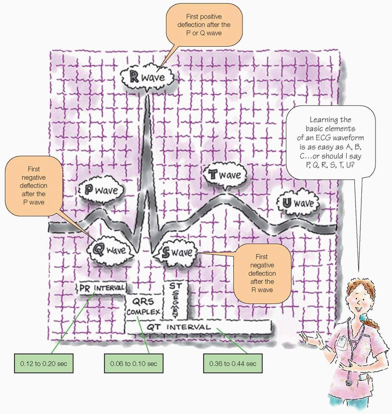
Count the number of small squares between the beginning of the P wave and the beginning of the QRS complex. Multiply the number of squares by 0.04 second. The normal interval is between 0.12 and 0.20 second, or between 3 and 5 small squares.
5 Calculate the duration of the QRS complex
Count the number of squares between the beginning and the end of the QRS complex and multiply that number by 0.04 second. A normal QRS complex is less than 0.12 second, or less than 3 small squares wide. Some references specify 0.06 to 0.10 second as the normal duration of the QRS complex. Check to see if all QRS complexes are the same size and shape, and note if a complex appears after every P wave.
6 Evaluate the T wave
Check that T waves are present and have a normal shape, normal amplitude, and the same deflection as QRS complexes. Consider whether a P wave could be hidden in a T wave by looking for extra bumps in the waveform.
7 Calculate the duration of the QT interval
Count the number of squares from the beginning of the QRS complex to the end of the T wave. Multiply this number by 0.04 second. The normal range is 0.36 to 0.44 second, or 9 to 11 small squares wide.
8 Evaluate other components
Quickly look for abnormally conducted beats and other abnormalities. Then make sure the waveform doesn’t reflect problems with the monitor. Next, check the ST segment for abnormalities and look for a U wave. Finally, classify the rhythm strip according to site of rhythm origin, rate, and rhythm.
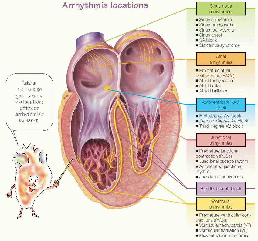
Arrhythmias
Cardiac arrhythmias are variations in the normal pattern of electrical stimulation of the heart. Arrhythmias range from mild, causing no symptoms and requiring no treatment (such as sinus arrhythmia), to those that require emergency intervention and may cause death (such as ventricular fibrillation).
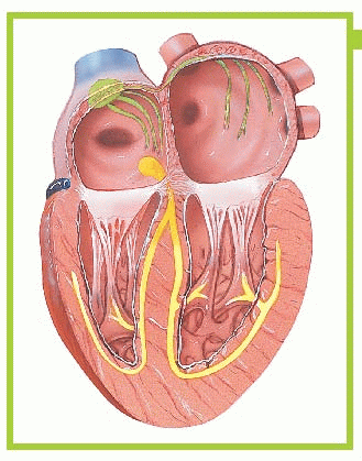
Sinus node arrhythmias
When the heart functions normally, the SA node, also called the sinus node, acts as the primary pacemaker. The SA node assumes this role because its automatic firing rate (60 to 100 beats/minute in an adult at rest) exceeds that of the heart’s other pacemakers. Sinus node arrhythmias occur when the node’s firing rate increases or decreases.
Pacemaker Rate
PACEMAKER |
RATE (BEATS/MINUTE) |
SA node |
60 to 100 |
AV node |
40 to 60 |
Purkinje fibers |
20 to 40 |
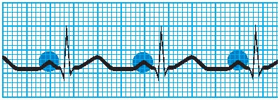
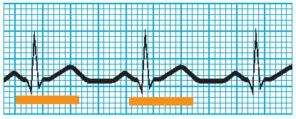
Sinus arrhythmia
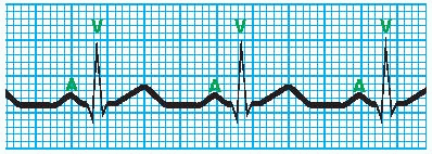
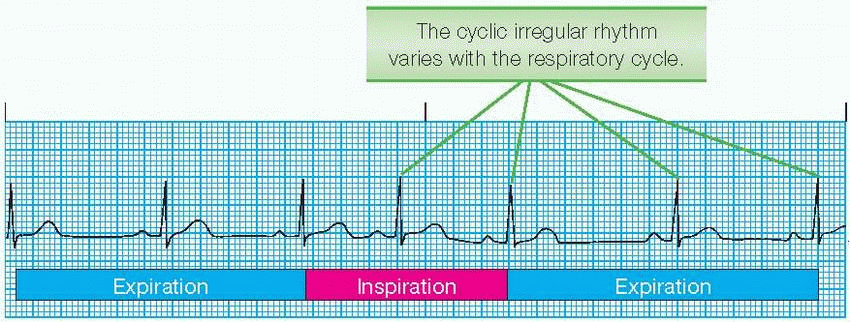
In sinus arrhythmia, the SA node fires irregularly. When sinus arrhythmia is related to respirations, heart rate increases with inspiration and decreases with expiration, as shown at right. Sinus arrhythmia may be caused by inferior-wall myocardial infarction (MI), use of digoxin (Lanoxin) or morphine (Roxanol), and increased intracranial pressure. If sinus arrhythmia is unrelated to respiration, the underlying cause may require treatment.
Rhythm
Irregular
Corresponds to the respiratory cycle
P-P interval and R-R interval shorter during respiratory inspiration; longer during expiration
Difference between longest and shortest P-P interval exceeds 0.12 second
PR interval
May vary slightly
Within normal limits
Twave
Normal size
Normal configuration
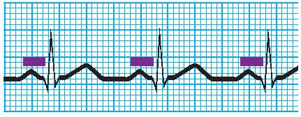
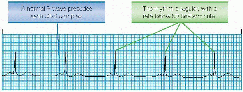
Sinus bradycardia
Sinus bradycardia is a heart rate less than 60 beats/minute. If the rate falls below 45 beats/minute, patients usually have signs and symptoms of decreased cardiac output, such as hypotension, dizziness, confusion and, possibly, syncope.
PR interval
Within normal limits
Constant
QRS complex
Normal duration
Normal configuration
T wave
Normal size
Normal configuration
QT interval
Within normal limits
Possibly prolonged
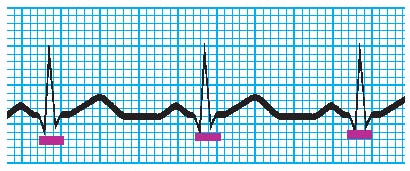
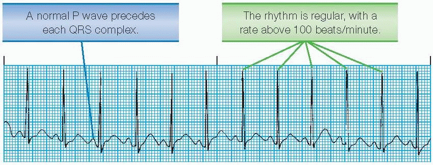
Sinus tachycardia
Sinus tachycardia in an adult is characterized by a sinus rate greater than 100 beats/minute. The rate rarely exceeds 180 beats/minute, except during strenuous exercise.
Sinus tachycardia in a patient who has had an acute MI suggests massive heart damage. Persistent tachycardia may signal impending heart failure or cardiogenic shock.
P wave
Normal size
Normal configuration
May increase in amplitude
Precedes each QRS complex
As heart rate increases, possibly superimposed on preceding T wave and difficult to identify
PR interval
Within normal limits
Constant
QRS complex
Normal duration
Normal configuration
T wave
Normal size
Normal configuration
QT interval
Within normal limits
Commonly shortened
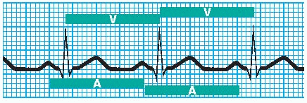
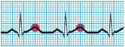
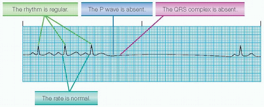
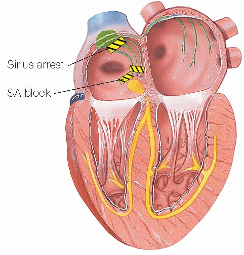
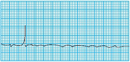
Sinus arrest
Atrial standstill occurs when the atria aren’t stimulated and an entire PQRST complex is missing from an otherwise normal ECG strip. Atrial standstill is called sinus pause if one or two beats aren’t formed and sinus arrest when three or more beats aren’t formed. Causes of sinus arrest include acute infection, heart disease, use of some drugs, and vagal stimulation.
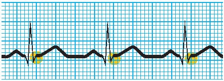
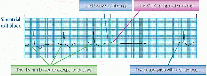
SA block
In SA block, the SA node discharges impulses at regular intervals, but some of those impulses are delayed on the way to the atria. The most common block is the SA exit block. SA block may result from acute infection, an inferior-wall MI, coronary artery disease (CAD), hypertensive heart disease, sinus node disease, or use of medications, such as beta-adrenergic blockers, calcium channel blockers, inotropics, or antiarrhythmics.
P wave
Periodically absent, with entire PQRST complex missing
When present, normal size and configuration and precedes each QRS complex
QRS complex
Normal duration
Normal configuration
Absent during a pause
T wave
Normal size
Normal configuration
Absent during a pause
QT interval
Within normal limits
Absent during a pause
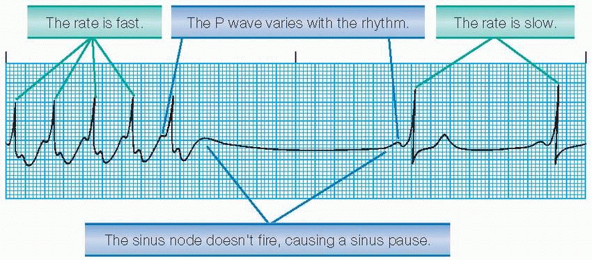
Sick sinus syndrome
Also called sinus nodal dysfunction, sick sinus syndrome results either from a dysfunction of the sinus node’s automaticity or from abnormal conduction or blockages of impulses coming out of the nodal region, including one or a combination of the following conditions:
sinus bradycardia
SA block
sinus arrest
sinus bradycardia alternating with sinus tachycardia
episodes of atrial tachyarrhythmias, such as atrial fibrillation and atrial flutter
failure of the sinus node to increase the heart rate with exercise.
Rhythm
Irregular
Sinus pauses
Abrupt rate changes