Digital Echocardiography
Mario J. Garcia
Over the last two decades, echocardiography has created a tremendous impact in health care. Much of the success of echocardiography is due to its ability to provide “live” moving images that can be reviewed and easily understood by all types of health-care providers and patients. This ability has been only minimally exploited in the past, given the limitations of analog technology. Meanwhile, other areas of medical imaging have adopted digital recording as the standard.
The first efforts in digital echocardiography occurred in the early 1980s. Given storage capacity and processing speed limitation, digital echo was limited to stress testing and evaluation of coronary artery disease, using a quadscreen format and grayscale images (1). New technological advances in echocardiography today permit registering moving images in digital format, allowing logical archival; rapid data retrieval, copy, and transfer; off-line quantitative analysis; and side-by-side comparison with superior image resolution (2).
The American Society of Echocardiography established a task force in 1992 to educate the echocardiographic community on the promise and pitfalls of digital echocardiography and advise the Digital Images and Communications in Medicine (DICOM) committee on a standard image format for echocardiography (3).
ANALOG VERSUS DIGITAL IMAGING
In order to appreciate the advantages of digital echocardiography, we first need to understand the fundamental principles of analog and digital imaging. The principal feature of analog representations is that they are continuous. In contrast, digital representations consist of values measured at discrete intervals. Analog technology refers to electronic transmission accomplished by adding signals of varying frequency or amplitude to carrier waves of a given frequency of alternating electromagnetic current. Analog data is typically represented as a series of sine waves. Television, radio, and telephone transmission mostly use analog technology, although more recently, the use of digital technology in these fields is rapidly expanding. A theoretical advantage of analog data is its ability to provide in theory an infinite spectrum of data. This is most easily appreciated when analyzing the fidelity of signals that are “naturally” analog, such as audio or video signals. In order to transform this data into a digital format, an electronic process known as analog-to-digital conversion needs to be implemented. The input to any analog-to-digital converter consists of a signal with a theoretically infinite number of values that has been transformed to an electrical voltage, and the output is a multi-level signal that has defined levels, typically a power of two (e.g., 2, 4, 8, 16, 32). Thus, the most basic digital signal has only two states and is called a binary signal, whereas the only possible values are 0 and 1. Any number can then be represented in binary form as sequences of zeros and ones. Because we are primarily interested in images in echocardiography, let’s analyze how a picture can be converted into digital data.
A rectangular image of theoretically unlimited resolution is first limited to a matrix of finite dimensions, e.g., 800 horizontal × 600 vertical lines (VGA resolution). This matrix then has 480,000 pixels (smallest distinct geographical square zone). In a picture each pixel may contain color information within a scale. The number of color values is given by a number of bits that are contained in each pixel, and is equal to two to the power of the number of bits; e.g., if there are three bits per pixel, then eight different values could be encoded (000, 001, 010, 100, 011, 101, 110, and 111). In a typical grayscale echocardiographic image, there are 256 shades of gray (8-bits per pixel, or 28 = 256). Thus, the size of the raw binary digital file that encodes the information contained in this picture is 400 × 600 × 8 = 384,000 bits (or 48,000 bytes, since 1 byte = 8 bits). If higher color definition is required, the number of bits per pixel may be increased. A 32-bit per pixel resolution provides 232 = 4,294,967,296 colors and will require 400 × 800 × 32 = 1,920,000 bits = 240,000 bytes. Regardless of its resolution, digital data has a finite limitation, and that is why, in theory, an audio signal recorded in analog format (vinyl record) may be reproduced
with higher fidelity than a digital recording (compact disc). If this is the case, what is the advantage of digital media?
with higher fidelity than a digital recording (compact disc). If this is the case, what is the advantage of digital media?
Digital signals travel more efficiently than analog signals, mainly because digital impulses, which are well defined, are easier for electronic circuits to distinguish from noise, which is chaotic. Noise can occur naturally or by electrical interference and is incorporated randomly to analog data during transmission, recording, processing, and display. In an audio recording, noise can be appreciated as background “hissing.” Once noise is introduced, it cannot be separated from the original signal and is compounded with more noise introduced during each additional process. Thus, every time that analog data is transferred and/or copied, signal-to-noise ratio decreases. For that reason, second copies of video or music analog recordings are never identical to their originals. Here lies one of the main advantages of digital media—it is capable of identically reproducing the original set of data.
COMPONENTS OF A DIGITAL LABORATORY
Data Acquisition
Cardiac ultrasound imaging equipment initially obtains analog data from the imaging transducer, where ultrasonic reflections stimulate a piezoelectric crystal to produce electrical impulses (Fig. 2.1). In order to convert these electrical impulses into images, they need to be processed by a computer that analyzes time delay, signal intensity, and frequency shifts in order to determine the location, density, and velocity of each cardiac structure. Because most computers can only process digital data, the original analog signals need to be transformed to digital signals. A process known as analog-to-digital conversion performs this task, during which continuous data is converted into discrete values. For example, color Doppler usually displays 32 velocity values (16 for each direction). Thus, for a Nyquist velocity of 64 cm/sec, each discrete velocity represents a multiple of 4 cm/sec, and the original analog input is rounded to the nearest digital value (e.g., 7 cm/sec to 8 cm/sec). At the time of digital processing, other pertinent data are added to the images (time and date, equipment settings, calibration data, patient demographics, etc.). However, binary digital impulses, all by themselves, appear as long strings of ones and zeros, and have no apparent meaning to a human observer. In order to display still or moving ultrasound images in a video monitor, they need to be converted to analog signals. The circuit that performs this function is a digital-to-analog converter.
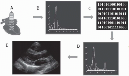 FIGURE 2.1. Generation of an echocardiographic image. A: Ultrasound pulses. B: Analog electrical impulses. C: Analog-to-digital conversion. D: Digital-to-analog conversion. E: Video output. Notice the distortion of the original signal by added noise (D). |
Basically, digital-to-analog conversion is the opposite of analog-to-digital conversion. Although this process is required as a final step in order to provide meaningful information to a human observer, it introduces noise and results in loss of the other pertinent data described above. Thus, the most efficient method to obtain true digital echocardiographic data requires direct output of digital images from an ultrasound machine, before digital-to-analog conversion. Selected cine-loops of fixed (temporal interval) or variable length (e.g., ECG-triggered, single or multiple cardiac cycles) may be then stored to disk or transmitted through a standard network. Most modern ultrasound systems provide digital output, though their implementation details may differ. With direct digital output, maximal fidelity is maintained, and calibration information is retained, facilitating quantitation on an off-line review workstation. An alternative to direct digital output is digitalization of video output data. This method permits
retrofitting of older ultrasounds systems, however, at the expense of some introduction of noise and without calibration information. Nevertheless, for legacy systems this is a quite acceptable way of integrating them into a digital laboratory. Most medium and large laboratories are familiar with the use of digitizing equipment used for stress echocardiography. Over recent years, several manufacturers have developed computer systems equipped with acquisition cards and dedicated software suitable for echocardiography. These systems take the direct video output used by the video recorder and monitor and reconvert the analog input to digital data. While virtually any generic product can be used to capture images, variable resolution adjustment, trimming, ECG triggering, labeling, and formatting capabilities are only available through dedicated commercially available systems.
retrofitting of older ultrasounds systems, however, at the expense of some introduction of noise and without calibration information. Nevertheless, for legacy systems this is a quite acceptable way of integrating them into a digital laboratory. Most medium and large laboratories are familiar with the use of digitizing equipment used for stress echocardiography. Over recent years, several manufacturers have developed computer systems equipped with acquisition cards and dedicated software suitable for echocardiography. These systems take the direct video output used by the video recorder and monitor and reconvert the analog input to digital data. While virtually any generic product can be used to capture images, variable resolution adjustment, trimming, ECG triggering, labeling, and formatting capabilities are only available through dedicated commercially available systems.
Data Compression
In order to efficiently store and transfer digital echocardiographic studies, some form of data compression is required. A single-frame echocardiographic image has a resolution of 640 horizontal × 480 vertical pixels × 24-bits per pixel, equalling 922 KB. Thus, at an average frame rate of 30 Hz, a 15 min uncompressed echocardiography study requires about 25 GB. Handling uncompressed data therefore becomes impractical, given current storage and transfer speed limitations.
One way of reducing the size of a digital echo study is by implementing clinical or “intelligent” compression. In a conventional echocardiographic study, a sonographer records 2-D and color Doppler images, as well as several M-Mode and spectral Doppler still frames obtained from multiple windows, angulations, and depths. Each segment recorded comprises several cardiac cycles. Using “intelligent” compression, representative video loops of a more limited length are acquired instead, either based on ECG-triggered cardiac cycles or on segments of fixed oneor two-second durations. A typical echocardiographic study may be reduced in this manner to about 30 loops of approximately one second each. A complete study, therefore, could consist of 30 seconds instead of 15 min of data, reduced to 0.8 GB, or in other words, achieving 30:1 compression. Intelligent compression works well most of the time, with minimal loss of diagnostic content, because single cardiac cycles contain mostly the same information that multiple repeated cardiac cycles obtained from the same view, angle, and depth do. There are pitfalls and limitations of intelligent compression, however, which will be discussed later in this chapter.
An alternative or complementary way to reduce the size of a digital echocardiographic study is the implementation of digital compression. Digital compression is obtained by specific mathematical algorithms that seek to summarize data redundancy within one image or over consecutive images in a temporal sequence. Two general forms of digital compression exist, lossless and lossy compression.
Lossless compression algorithms, such as run length encoding (RLE), reduce only redundant information. For example, in an echo image, the pixels of the nonimage portion of the 640 × 480 matrix outside the scan sector always has the same value and thus can be reduced to a simple mathematical expression. Converting the grayscale areas of a color Doppler image to an 8-bit depth (256 shades of gray per pixel) can also reduce image size, without content loss. Most lossless compression algorithms, however, can achieve only modest reductions in file size, typically 2:1 to 3:1.
Conversely, lossy compression can achieve 20:1 or greater data reduction. Lossy compression algorithms, such as the LZW used for Target Image File Format (TIFF) images or the Joint Photography Expert Group (JPEG) format, are commonly used for still-frame images and have been adopted by DICOM. The JPEG compression format includes 29 distinct coding processes and provides adjustable compression quality; the greater quality factor corresponding to the lesser compression (Fig. 2.2). Therefore, a tradeoff can be made between image quality and file size. The JPEG compression algorithm uses a frequency-based transform (Discrete Cosine Transform or DCT), a quantization technique for losing selective information that can be acceptably lost from visual information and Huffman coding, a technique of lossless compression that uses code tables based on statistics about the encoded data. The JPEG compression scheme has demonstrated in clinical studies to be usable in echocardiography at compression ratios of 20:1 or higher (4,5,6). Additionally, clinical studies have shown that interpretations made by digital acquisitions are accurate in comparison to the traditional videotape review (7,8,9).
Other lossy compression algorithms are specifically designed for motion sequences. The MJPEG algorithm applies JPEG compression to each individual image in a sequence. The Moving Picture Experts Group (MPEG) format also employs temporal compression, exploiting the redundancies in the temporal domain. MPEG is the current motion picture industry standard for digital video (DVD) and digital audio compression. There are multiple MPEG formats, each designed for a different purpose. MPEG-1 was originally designed for encoding video for broadcasting at a transmission rate of about 1.5 Mbps (millions of bits per second). MPEG-1 audio layer-3 (MP3) is a variation of this format used for compressing digital audio. MPEG-2 can encode interlaced images at transmission rates over 4 Mbps and is used for digital TV broadcast via cable or satellite. MPEG-1 and -2 can compress digital video by factors varying from 25:1 to 50:1. Both MPEG-2 and MPEG-3 may be used to broadcast
High Definition Television (HDTV) signals. MPEG-4 is the newest standard developed and used for Direct Video Disc (DVD). In addition to the techniques used for JPEG compression, MPEG uses motion-compensated predictive coding, in which the differences in what has changed between an image and its preceding image are calculated and only the differences are encoded, as well as bidirectional prediction, in which some images are predicted from the pictures immediately preceding and following the image. MPEG-1 (10,11,12,13) and MPEG-2 (14) have been shown to be useful transfer syntaxes in echocardiography, and have been clinically validated at compression ratios up to 100:1. In a recent multicenter study, we demonstrated the clinical capability of MPEG-recorded echocardiograms (15). We have continued to investigate the use of MPEG compression and its effect on quantitative measures (16). Six reviewers performed blind measurements from still-frame images selected from 20 echocardiographic studies simultaneously acquired in s-VHS and MPEG-1 format. Measurements were obtainable in 1,401 of 1,486 (95%) MPEG-1 variables versus 1,356 of 1,486 (91%) sVHS variables (p < 0.001). There was excellent agreement between MPEG-1 and sVHS two-dimensional linear (r = 0.97, MPEG-1 = 0.95 sVHS + 1.1 mm, p < 0.001, Δ = 9 ± 10%), two-dimensional area measurements (r = 0.89), color jet areas (r = 0.87, p < 0.001), and Doppler velocities (r = 0.92, p < 0.001). Interobserver variability was similar for both sVHS and MPEG-1 readings. Our results indicate that quantitative off-line measurements from MPEG-1 digitized echo studies are feasible and comparable to those obtained from sVHS. However, as of today, MPEG formats have not been incorporated by DICOM. Ultrasound equipment manufacturers have not adopted this technology due to the high cost of the hardware required for MPEG encoding. Nevertheless, independent companies have developed and marketed systems that can be adapted to existing ultrasound machines.
High Definition Television (HDTV) signals. MPEG-4 is the newest standard developed and used for Direct Video Disc (DVD). In addition to the techniques used for JPEG compression, MPEG uses motion-compensated predictive coding, in which the differences in what has changed between an image and its preceding image are calculated and only the differences are encoded, as well as bidirectional prediction, in which some images are predicted from the pictures immediately preceding and following the image. MPEG-1 (10,11,12,13) and MPEG-2 (14) have been shown to be useful transfer syntaxes in echocardiography, and have been clinically validated at compression ratios up to 100:1. In a recent multicenter study, we demonstrated the clinical capability of MPEG-recorded echocardiograms (15). We have continued to investigate the use of MPEG compression and its effect on quantitative measures (16). Six reviewers performed blind measurements from still-frame images selected from 20 echocardiographic studies simultaneously acquired in s-VHS and MPEG-1 format. Measurements were obtainable in 1,401 of 1,486 (95%) MPEG-1 variables versus 1,356 of 1,486 (91%) sVHS variables (p < 0.001). There was excellent agreement between MPEG-1 and sVHS two-dimensional linear (r = 0.97, MPEG-1 = 0.95 sVHS + 1.1 mm, p < 0.001, Δ = 9 ± 10%), two-dimensional area measurements (r = 0.89), color jet areas (r = 0.87, p < 0.001), and Doppler velocities (r = 0.92, p < 0.001). Interobserver variability was similar for both sVHS and MPEG-1 readings. Our results indicate that quantitative off-line measurements from MPEG-1 digitized echo studies are feasible and comparable to those obtained from sVHS. However, as of today, MPEG formats have not been incorporated by DICOM. Ultrasound equipment manufacturers have not adopted this technology due to the high cost of the hardware required for MPEG encoding. Nevertheless, independent companies have developed and marketed systems that can be adapted to existing ultrasound machines.
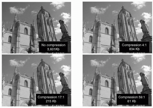 FIGURE 2.2. Impact of JPEG image compression on image quality and file size. |
Future compression schemes, such as wavelet compression, promise even more efficiency (quality-to-file size ratio). Wavelets are mathematical functions similar to Fourier analysis, which make recovery of weak signals from noise possible. Wavelet-compressed images can further reduce file size by a factor of 4:1 compared to JPEG. In wavelet compression, images are converted into a set of mathematical expressions. We have investigated the application of the wavelet transform to two-dimensional sequences of image data derived from digital subtraction of consecutive frames. Images were divided into primary (P) and delta (Δ) frames, with the image content of each Δ frame defined as the difference from the previous P frame. A wavelet- compression algorithm utilizing difference image data (1P:4Δ) results in a CR of nearly 100:1 and an improved SNR (P: 36.5 ± 0.05, Δ: 32.4 ± 0.13 dB) compared with JPEG (31.96 ± 0.10 dB, CR = 20:1). More recently this approach has been extended using a three-dimensional wavelet transform for the compression of echocardiographic sequences (17, 18).
Data Transfer
Network transfer is the most efficient method for delivering echocardiographic studies from the acquisition to the interpretation and to the final storage location. A network
is a series of nodes (input and output devices) interconnected by communication paths. Networks can be characterized in terms of spatial distance as local area networks (LAN), metropolitan area networks (MAN), and wide area networks (WAN). A LAN is a group of computers and associated devices that share a common communications line and typically share the resources of a single main computer or server within a small geographic area (such as the ones used in a medical office building or hospital setting within an office building). Usually, the server has specific applications and data storage that are shared by multiple computer users. Individual users needing applications can download and upgrade them as frequently as needed, and run them from their local computers. Networks permit the sharing of common resources, such as viewer stations and printers. Thus multiple people can simultaneously access the same data—an important advantage of the digital echocardiographic laboratory that cannot be matched with analog video technology. A user can share files with others on the LAN server; but read and write privileges can be restricted at multiple levels by a LAN administrator. Thus, other unique advantages of the digital echo lab are data redundancy and tight data security. A network can be characterized by the type of data transmission in use (TCP/IP or System Network Architecture); by the usual nature of its connections (dial-up or switched, dedicated or non-switched, or virtual connections); and by the types of physical links. All these variables in turn determine data-transfer speed.
is a series of nodes (input and output devices) interconnected by communication paths. Networks can be characterized in terms of spatial distance as local area networks (LAN), metropolitan area networks (MAN), and wide area networks (WAN). A LAN is a group of computers and associated devices that share a common communications line and typically share the resources of a single main computer or server within a small geographic area (such as the ones used in a medical office building or hospital setting within an office building). Usually, the server has specific applications and data storage that are shared by multiple computer users. Individual users needing applications can download and upgrade them as frequently as needed, and run them from their local computers. Networks permit the sharing of common resources, such as viewer stations and printers. Thus multiple people can simultaneously access the same data—an important advantage of the digital echocardiographic laboratory that cannot be matched with analog video technology. A user can share files with others on the LAN server; but read and write privileges can be restricted at multiple levels by a LAN administrator. Thus, other unique advantages of the digital echo lab are data redundancy and tight data security. A network can be characterized by the type of data transmission in use (TCP/IP or System Network Architecture); by the usual nature of its connections (dial-up or switched, dedicated or non-switched, or virtual connections); and by the types of physical links. All these variables in turn determine data-transfer speed.
Ethernet is the most widely installed LAN technology. An Ethernet LAN can use different types of physical links, such as twisted pair wires, coaxial cable, or optical fiber. The most commonly installed Ethernet systems are 10BASE-T, and provide transmission speeds up to 10 Mbps (Megabits or million bits per second). “BASE” indicates baseband signaling, which means that only Ethernet signals are carried on the medium, and “T” represents twisted-pair. In addition to 10BASE-T, 10-megabit Ethernet can be implemented with other media types: 10BASE-2, using thin-wire coaxial cable, provides a maximum segment length of 185 meters; 10BASE-5, using thick-wire coaxial cable, maintains a signal up to 500 meters; 10BASE-F, using optical fiber, which carries much more information than conventional copper wire, is in general not subject to electromagnetic interference; and 10BASE-36, using broadband coaxial cable, carries multiple baseband channels for a maximum length of 3.6 kilometers. Fast Ethernet provides transmission speeds up to 100 megabits per second (100BASE-T) and can also have different types of physical connection: 100BASE-T4 (four pairs of copper-twisted wire), 100BASE-TX (two pairs of data-grade twisted-pair wire), and 100BASE-FX (twostrand optical fiber cable). Gigabit Ethernet provides 1 gigabit (or 1 billion bits) per second and it uses primarily optical fiber cable. Other technology available that can transfer data at even higher speeds, such as ATM (asynchronous transfer mode) and 10-Gigabit Internet, are not so practical for internal implementation but will likely play a significant role in the future of digital echocardiography in telemedicine.
A network is built in a manner similar to the building of a road system: many smaller one-lane country roads lead to two-lane roads that lead to a few multiple-lane highways as one approaches areas of major traffic. Thus, in a network, 10BASE-T Ethernet may be used to connect individual users (such as physicians’ offices) to the server, while 100BASE-T is used to connect areas of higher traffic (ultrasound machines and central reading stations for the server), and Gigabit Ethernet may serve as the system backbone (connecting the server to storage devices). LAN Devices (ultrasound machines, viewing stations, etc.) are connected to the cable with 10BASE-T or 100BASE-T network cards. A network card or adapter is a circuitry designed to provide expanded capability to a computer. It is provided on the surface of a standard-size rigid material and then plugged into one of the internal ultrasound machine computer’s expansion slots in its motherboard. A network card can control a device (such as a hard disk drive) from a remote connection. LAN devices may compete for access at any given time, thus a protocol using carrier sense multiple access with collision detection (CSMA/CD) is implemented, which acts as a “traffic light.” A large network operates more efficiently with the implementation of network switches. A switch is a device that selects a path or circuit for sending a unit of data to its next destination. A switch may also include the function of a router, a device or program that can determine the route and specifically what adjacent network point the data should be sent to. Network switches, also known as layer-three switches or IP switches, control traffic among LAN devices that have specific IP addresses. A network connection can be used exclusively for a given time interval by two or more LAN devices and then switched for use to another set of parties. This type of all-or-nothing switching is known as circuit-switching and is primarily used for telephone communications. Alternatively, using packet-switching, multiple LAN devices can share the same paths at the same time and the particular route a data unit travels can be varied as traffic conditions change in the network. In packet-switching, a file is divided into packets, which are units of a certain number of bytes. The network addresses of the sender and of the destination are added to each packet. Packets from the same file may travel different routes and arrive at different times, but at their destination, these are reassembled into the original file. Packet-switching is the preferred method implemented in computer network communications.
Stay updated, free articles. Join our Telegram channel

Full access? Get Clinical Tree


