CVMR: Imaging Planes and Anatomy
Harrie C.M. van den Bosch
Jos J.M. Westenberg
Albert de Roos
Cardiac magnetic resonance (CVMR) imaging has the ability to provide arbitrary views of the cardiac structures which can be chosen freely since this modality is not hampered by the availability of acoustic windows, as in echocardiography. Even though echocardiography, x-ray LV angiography, and cardiac computed tomography (CT) are nowadays commonly used techniques for evaluating cardiac disease in clinical practice, CVMR has evolved to become the preferential technique for anatomic and functional cardiac imaging.
Two-dimensional (2D), single-plane, multiple-2D, or three-dimensional (3D) imaging is possible with CVMR. Furthermore, temporal information of the dynamics of the heart can be provided as imaging is synchronized to the cardiac frequency, using either prospective triggering or retrospective gating (1). With prospective triggering, the operator will set the expected heart rate before the acquisition and triggering will be performed according to this chosen heart rate. With retrospective gating, imaging is performed continuously and additionally the ECG signal will be stored. In retrospect, k-space filling is synchronized to the stored ECG. This synchronization enables time-resolved imaging and multiple phases of the cardiac cycle can be obtained. The acquired views in multiple phase of the heart can be presented in cine mode, providing functional information on the temporal behavior of the cardiac structures.
Imaging planes in CVMR are usually obtained in the orientation to the axes of the heart, or oriented to the major axes of the body. Therefore, the standard CVMR planes of the heart are comparable to the standard cardiac views known and established in other noninvasive imaging modalities such as echocardiography, cardiac CT, x-ray LV angiog-raphy, and nuclear techniques (e.g., single-photon emission computed tomography [SPECT] and positron emission tomography [PET]). Compared to cardiac CT, x-ray angiog-raphy, and nuclear techniques, CVMR allows noninvasive, high-resolution imaging without using ionizing radiation. Furthermore, the morphology of the right ventricle (RV) is excellent delineated by CVMR, whereas in echocardiogra-phy the assessment of RV geometry and function is challenging because of the particular crescentic shape of the RV wrapping around the left ventricle (LV) (2).
The choice for a specific scan protocol is mainly determined by the diagnostic question which has to be answered. In CVMR imaging, both static and dynamic images of the heart can be acquired. Therefore, it is important to be adequately informed by the referring clinician prior to the CVMR examination. Standardized nomenclature for cross-sectional anatomy has been described (3), facilitating comparison between different techniques and proper communication in clinical practice. The 17-segment model of the LV, proposed by the American Heart Association (AHA), is nowadays widely used and accepted in clinical CVMR imaging, as in other cross-sectional imaging modalities (e.g., cardiac CT and nuclear techniques). The recommended model comprehends six basal segments, six mid-ventricular segments, four apical (distal) segments, and one true apex (Fig. 7.1). These 17 segments are routinely evaluated when regional LV performance is questioned.
Another important issue in clinical CVMR imaging is the ability of the patient to cooperate during the examination and to perform breath-holding. If a patient is capable to perform breath-holding, successive scan planes are obtained with accelerated imaging, with the patient usually performing breath-holding in expiration. Preferably, image planes in CVMR imaging are acquired in mid- or end-expiration, as the anatomic level may be obtained more reproducible compared to planes which are scanned in inspiration (4).
For planning purposes, new generation clinical MR scanners provide the possibility to plan the various scan planes interactively with real-time imaging. During free-breathing CVMR, planning can be performed accurately. After all scan planes are defined and obtained interactively, the acquisition of the cine long-axis (LA) and short-axis (SA) views may be performed during breath-holding. This interactive approach for planning is fast, reliable, and patient friendly, and essential in patients who are not capable to hold their breath consecutively, for example, patients with respiratory disease or with heart failure. Fully automated CVMR planning
methods have also been described and can provide accurate and reproducible measurements of LV dimensions (5).
methods have also been described and can provide accurate and reproducible measurements of LV dimensions (5).
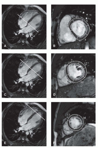 Figure 7.1. The standardized 17 segments of LV as proposed by the American Heart Association. At basal (B) and mid-ventricular (D) level, the myocardium is divided into six segments each, and at apical (F) level, the myocardium is divided into four segments. Nomenclature: Segment 1, basal anterior; 2, basal anteroseptal; 3, basal inferoseptal; 4, basal inferior; 5, basal inferolateral; 6, basal anterolateral; 7, mid-anterior; 8, mid-anteroseptal; 9, mid-inferoseptal; 10, mid-inferior; 11, mid-inferolateral; 12, mid-anterolateral; 13, apical anterior; 14, apical septal; 15, apical inferior; 16, apical lateral. Segment 17 (not presented) is the true apex, which can be evaluated on a long-axis view. Dashed lines on the four-chamber view (A,C and E) indicate the planning of the acquisition level. |
With CVMR, the choice of scanning technique is aimed at the choice between bright-blood and black-blood imaging, which essentially determines the contrast between myocardium and the intra-cardiac blood pool. For the assessment of left and right ventricular function, fast gradient-echo sequences are usually performed in combination with steady-state free precession (SSFP) technique (balanced-TFE, True-FISP, Fiesta) for optimal contrast. On these images, the blood pool is presented with bright signal whereas the myocardium is represented dark with low signal. This results in an excellent definition of the LV endocardial and epicardial borders, which is required for accurate image segmentation during cardiac volume and function quantification. Typically, SSFP images should be acquired with slice thickness of 6 to 8 mm and temporal resolution better than 45 milliseconds to obtain optimal accuracy in ventricular function assessment (6,7).
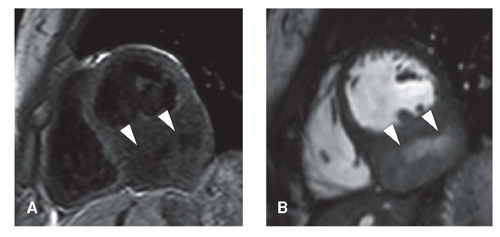 Figure 7.2. Black-blood (A) and bright-blood (B) short-axis acquisition illustrating a cardiac sarcoma (arrow heads) in the inferior wall, acquired in a 19-year-old female. |
In addition, cardiac morphology can be evaluated by double-inversion, black-blood, spin-echo sequences with fat suppression, providing static images of the heart with high spatial resolution (optimally, in-plane acquired resolution of better than 2 × 2 mm and slice thickness of 5 to 8 mm) in the orientation of the heart or the patient’s body axes. These images are, for example, obtained in the work-up of congenital heart disease or cardiac tumors (Fig. 7.2).
In the remainder of this chapter, the planning of the specific imaging planes will be discussed, as well as the normal cardiac structures that are visualized. Furthermore, the aspects of cardiac imaging on (ultra-) high-field MRI will be addressed.
CARDIAC AXIS IMAGING PlANES
To acquire imaging planes in the direction of the cardiac axes, multi-stack, single-shot SSFP scout views are used for planning. If available, free-breathing real-time scanning can be used instead that is advantageous for patient’s comfort. Perpendicular to an anatomical transverse image, displaying the heart’s four chambers, an acquisition plane is chosen through the middle of the atrioventricular junction at the level of the mitral valve and running through the apex (Fig. 7.3). This plane is the so-called vertical long-axis (VLA) plane. On this VLA view, a plane is defined intersecting the apex and the middle of the mitral valve, resulting in the horizontal long-axis (HLA) view. The HLA view is almost comparable to the four-chamber view; however, in this HLA view often a part of the LV outflow tract (LVOT) is visualized. On the acquired HLA plane, the SA views covering the entire LV are planned parallel to the ring of the mitral valve and perpendicular to the line intersecting the apex.
For reasons of reproducibility and comparison, the true two- and four-chamber view can still be obtained. The two-chamber view is planned perpendicular to the anterior and inferior wall of the LV through the center of the LV cavity on a mid-ventricular SA image intersecting the apex. On the two-chamber view, the apex, anterior and inferior wall of the LV, the mitral valve, and left atrium can be analyzed (Fig. 7.4A). The four-chamber view is planned also on
a mid-ventricular SA image by a plane through the center of the LV cavity and the acute margin of the RV, also intersecting the apex. The four-chamber view depicts the inferior interventricular septum, the anterior lateral wall of the LV, the free wall of the RV, left and right atrium as the interatrial septum, and both the mitral and tricuspid valves (Fig. 7.4B).
a mid-ventricular SA image by a plane through the center of the LV cavity and the acute margin of the RV, also intersecting the apex. The four-chamber view depicts the inferior interventricular septum, the anterior lateral wall of the LV, the free wall of the RV, left and right atrium as the interatrial septum, and both the mitral and tricuspid valves (Fig. 7.4B).
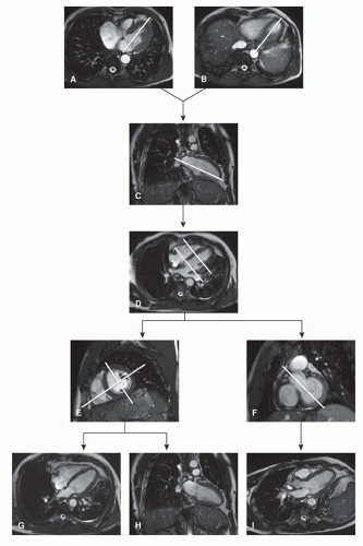 Figure 7.3. Planning acquisition of standard cardiac views. On two transverse slices (A) and (B), the left ventricular vertical long-axis (VLA) (C) is planned by a plane transecting the mitral valve and the apex. The horizontal long-axis (HLA) (D) is obtained by acquiring a plane transecting the VLA through the mitral valve and apex. A short-axis image can be obtained perpendicular to HLA, at mid-ventricular (E) and basal level (F). The four-chamber (G) of the LV is obtained as indicated from a plane transecting both LV and RV. The two-chamber (H) of the LV is acquired perpendicular to the four-chamber. The three-chamber LV (I) is obtained from a plane transecting the LV through the LVOT. |
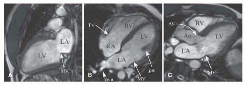 Figure 7.4. Normal cardiac anatomy on two-(A), four-(B), and three-chamber (C) views. LA, left atrium; LV, left ventricle; MV, mitral valve; TV, tricuspid valve; RV, right ventricle; RA, right atrium; pm, papillary muscle; AV, aortic valve; Ao, aorta. |
Stay updated, free articles. Join our Telegram channel

Full access? Get Clinical Tree


