Fig. 21.1
ECG leads attachment. The number and preferred location of leads depend on the scanner type and design. ECG leads should be attached outside scan range to avoid artifact from the ECG electrodes and cables. (a) With Brilliance CT (Philips), two upper ECG leads are placed between the 2nd and 4th intercostal spaces on the midclavicular line, and 3rd lower lead is placed on the left mid-abdomen, approximately 10 cm from the umbilicus (not shown). (b) With Somatom definition flash (Siemens), the number of ECG leads is four. Two upper leads are placed on the midclavicular line, directly below the clavicle. Two lower leads are placed on the midclavicular line, 6th or 7th intercostal space
Patient education such as breathing instruction and practice.
21.1.3 Heart Rate Control
To lower the heart rate and to make the regular rhythm during cardiac CT, β-blockers are the first-line treatment agent (Fig. 21.2).
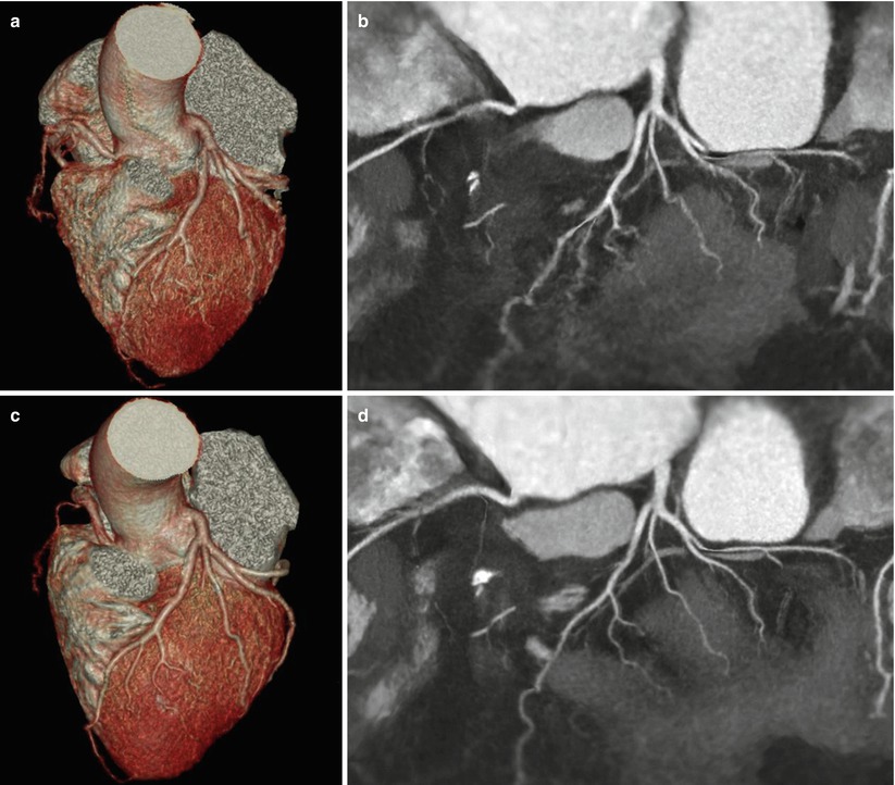
Fig. 21.2
Heart rate control. (a, b) The VRT and two-dimensional (2-D) map view in a patient with 90 bpm heart rate shows blurring at proximal RCA and all branches of LAD and LCX. (c, d) The VRT and 2-D map view after β-blocker administration in the same patient show decreased motion blurring and allow clear delineation of branches. VRT volume rendered technique, RCA right coronary artery, LAD left anterior descending, LCX left circumflex
Metoprolol and then atenolol are the most commonly used cardioselective β-blockers.
Effect of β-blockers [3]
Reduce the heart rate
Helpful in patients with irregular heart rates, such as premature atrial or ventricular contractions, supraventricular tachycardias, and atrial fibrillation
Prevent the heart rate variation following contrast injection and nitroglycerine administration
Diminish the diagnostic value of left ventricular function analysis due to negative inotropic effect
Contraindication of β-blocker
Allergy to β-blocker
Sinus bradycardia (HR <60 bpm)
Hypotension (systolic blood pressure <100 mmHg)
Decompensated cardiac failure
Current asthma or severe COPD dependent on β2-agonist inhaler
Active bronchospasm
Second- or third-degree atrioventricular block
Administration of β-blocker
Oral administration: 50–100 mg of metoprolol administered orally 1 h prior to CT scanning. → After 1 h, if the heart rate is not in the desired range, additional intravenous β-blocker administration should be considered.
IV β-blocker administration: Initially, 2.5 mg dose of metoprolol IV over 1 min → a second dose of 2.5 mg of metoprolol, if the heart rate remains more than 65 bpm after 5 min. → Up to two additional doses of 5 mg each of metoprolol can be given IV, each over 1 min, with a 5 min interval between doses, if the heart rate continues to remain elevated [3].
Calcium channel blockers are an alternative medication. However, the effectiveness of calcium channel blockers for heart rate reduction is considerably less than that of β-blockers.
Ivabradine is a pure heart rate-lowering agent, but does not depress myocardial contractility.
21.1.4 Nitroglycerin (NTG)
Nitroglycerin is a potent vasodilator, which dilates both normal and abnormal coronary arteries by relaxing the vascular smooth muscle.
The use of nitroglycerin actually improved diagnostic accuracy of coronary CTA for the evaluation of coronary artery disease in proximal segment and allows more septal branches to be visualized as well (Fig. 21.3) [4].
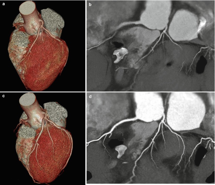
Fig. 21.3
Effect of nitroglycerin (NTG). (a, b) A 54-year-old female underwent an initial coronary CTA without NTG administration. The VRT and 2-D map view could not fully reveal the branches of the coronary arteries. (c, d) The same patient underwent a second coronary CTA with NTG administration. Coronary arteries are dilated sufficiently, and the VRT and 2-D map view show normal coronary arteries with excellent visualization of the branches
Contraindication of NTG
Hypersensitivity to NTG
Systolic hypotension (<100 mmHg)
Severe anemia
Severe aortic stenosis
Obstructive hypertrophic cardiomyopathy
Constrictive pericarditis
Acute RV infarction
Increased intracranial pressure
Glaucoma
Use of phosphodiesterase type 5 (PDE5) inhibitors such as Viagra® (sildenafil) or Levitra® (vardenafil) in the last 24 h or Cialis® (tadalafil) in the last 48 h
Administration of NTG [5]
Single tablet of nitroglycerin (0.4–0.6 mg) sublingually 1–2 min before CT scanning
Two puffs (400–800 mcg) of sublingual spray 5 min before initiation of CT scanning
21.2 Acquisition Parameters
21.2.1 Tube Voltage
Tube voltage value of 120 kVp is routinely used for most patients, while lower tube voltage of 80–100 kVp is a viable method to reduce radiation doses in pediatric patients and slim young adult with low body mass index (BMI) <25 kg/m2.
Lower tube voltage settings increase image noise, resulting in degradation of the coronary images. Therefore, tube voltage setting should be determined by considering balance of image quality and radiation dose.
According to the SCCT guideline [7], tube potential of 100 kV could be considered for patients weighing ≤90 kg or with a BMI ≤30 kg/m2; a tube potential of 120 kV is usually indicated for patients weighing >90 kg and with a BMI >30 kg/m2.
21.2.2 Tube Current
Tube current (mA) may be manually selected or protocolized based on the patient’s BMI and chest circumference (Table 21.1) and generally ranges between 300 and 800 mA.
Table 21.1
Optimal tube voltage and tube current tailored for BMI
BMI (kg/m2)
Tube voltage (kVp)
Tube current (mA)
<22.5
100
450
22.5–24.9
100
500
25–27.4
120
550
27.5–29.9
120
600
30–40
120
650
>40
120
700
mAs = mA × rotation time
Eff mAs = mAs/pitch factor
Higher tube current improves image quality and is useful in heavily calcified coronary artery, intracoronary stent, and obese patients.
21.2.3 Gantry Rotation Time (Speed)
Time required for the x-ray tube/detector system to rotate 360° around the patient.
For cardiac CT examination, the fastest gantry rotation time is typically selected.
Faster gantry rotation means faster acquisition of the data and subsequently improved temporal resolution.
The gantry rotation times of the most recent scanners range from 270 to 350 ms [8].
21.2.4 Collimation
Detector collimation [9]
Describes how the individual detector elements are used to channel data.
Depends on the number and width of detector element.
Determines the minimum section thickness (voxel length)
The minimum channel widths of recent MDCT range from 0.5 to 0.625 mm.
Beam collimation (total x-ray beam width)
Refers to the beam width along the longitudinal axis and can be calculated by multiplying the number of active channels by the channel width during the image acquisition.
A detector with 64 channels and a 0.625 mm channel width requires a 40 mm beam width.
21.2.5 Table Increment (Feed) and Pitch
Pitch is defined as the longitudinal (z-axis) table increment during one gantry rotation (360°) to total x-ray beam width [9].
In retrospective ECG-gated CT, typical pitch factors for cardiac MDCT range from 0.2 to 0.4.
If selected pitch is too high for a given heart rate, there will be gaps in the data, resulting in volume gap (or 3D gap) artifact between image stack with missing cardiac anatomy (Fig. 21.4).
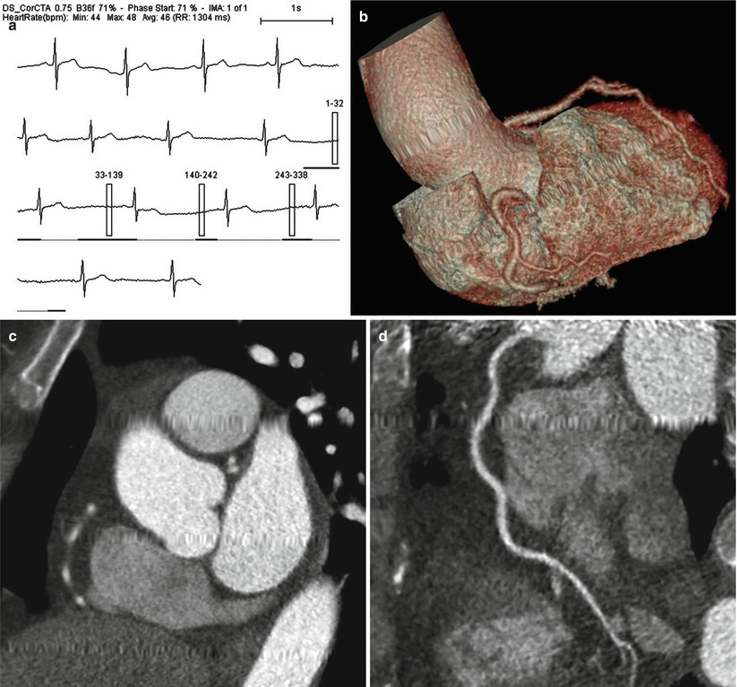
Fig. 21.4
Volume gap due to too high pitch. (a) ECG information in a patient with bradycardia (average heart rate of 46 bpm) and heart rate variation represents retrospective ECG-gated technique with ECG-based tube modulation. (b–d) VRT, short-axis, and curved MPR images in the patient show missing cardiac anatomies that could not be covered by the scanning
Automatic determination of pitch (automatic pitch adaptation or adaptive pitch technique) is available with dual-source CT scanners, which automatically adjust the pitch value to the patient’s heart rate.
21.2.6 Field of View (FOV) and Scan Range
The field of view (FOV) [10]
Represents the size of the image that is going to be reconstructed.
FOV of 200–250 mm or less is suitable for cardiac CT.
Scan range
For coronary CTA: from the carina to the bottom of the heart (approximately 10–12 cm long)
In patients who underwent bypass grafts: extended upper range to the middle of the clavicle (18–25 cm)
21.3 Acquisition Modes (Scan Techniques)
21.3.1 Prospective ECG Triggering (Step-and-Shoot or Sequential Mode)
Image acquisition technique [11]
The x-ray tube is turned on only during a certain previously defined phase of the R–R interval, but no radiation is delivered during the remainder of the R–R interval (Fig. 21.5).
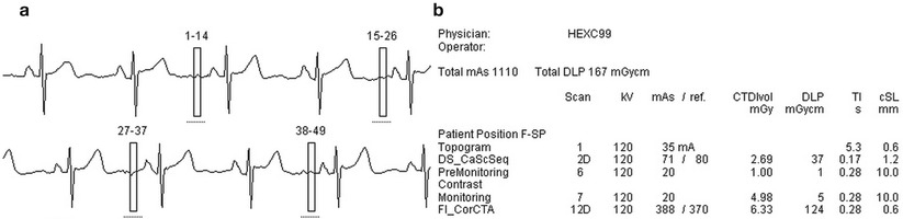
Fig. 21.5
Prospective ECG-triggered technique. (a) In a patient with 63 bpm of heart rate, prospective ECG-triggering technique is optimal choice. ECG information represents that the radiation exposure has allowed at only 70 % of R–R interval. (b) The total effective radiation dose of the CT examination including calcium scoring study is 2.34 mSv
Seventy percent of the R–R interval is optimal phase in patients with a low and stable heart rate.
This technique is mainly used for quantification of coronary calcium, but recently it is increasingly used for coronary CTA examinations.
Advantage and limitation of prospective ECG triggering
Relatively lower radiation dose of 3–5 mSv.
Image quality is dependent on the heart rate and heart rate variation.
Maximum heart rate threshold for prospective ECG triggering is between 60 and 65 bmp of single-source CT and <75 bpm for dual-source CT, respectively.
Functional information about cardiac valve motion or wall motion is not available.
Recent improvement of prospective ECG-triggering technique.
Longer z-axis coverage available with 256- or 320-slice scanners ranging from 12.8 to 16 cm in one gantry rotation permits full cardiac coverage in one gantry rotation with prospective ECG triggering.
With adaptive scan delay (multiphase adaptive prospectively gated axial CT), scan will be triggered on the basis of multiple previous R–R intervals, which is more likely to result in an optimally timed acquisition.
The lengthening (padding) of the x-ray tube on time allows a reconstruction in another phase, if motion artifact is problematic in one phase.
21.3.2 Retrospective ECG Gating
Image acquisition technique [11]
Images are acquired throughout the entire cardiac cycle during simultaneous ECG recording (Fig. 21.6).
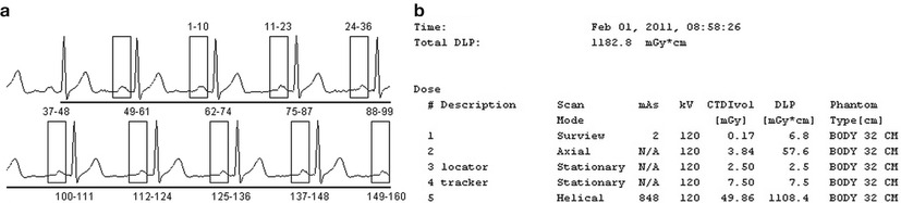
Fig. 21.6
Retrospective ECG-gating technique. (a) In a patient with 71 bpm of heart rate, retrospective ECG-gated technique acquires images through the entire cardiac cycle. Image reconstruction has been performed in 65 % of R–R interval retrospectively. (b) The total effective radiation dose of the CT examination including calcium scoring study is 16.5 mSv, which is higher than that of prospective ECG-triggered technique
Image reconstruction is performed in specific periods of the cardiac cycle retrospectively referencing to the ECG signal.
A low pitch (0.2–0.4) is needed to avoid gaps in anatomic coverage.
Advantage and limitation of retrospective ECG-gating technique
Less dependent on heart rate and allows ECG editing retrospectively
Evaluates cardiac function, such as potential regional function and wall motion abnormalities
Higher radiation exposure of between 12 and 20 mSv
ECG-based tube current modulation (ECG-pulsing) technique
A lower tube current during the systolic phase, because the majority of useful information is acquired in diastole phase
Low heart rate <65 bpm → pulsing window of 65–75 % of R–R interval (Fig. 21.7)
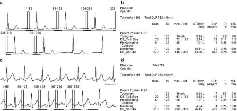
Fig. 21.7
Retrospective ECG-gated technique with ECG-based tube current modulation. (a, b) In retrospective, ECG-gated CT with 120 kVp and tube current modulation. Pulsing window ranges from 65 to 75 %. The total effective radiation dose is 10.1 mSv from conversion factor of 0.014 and total DLP of 722 mGycm. (c, d) With retrospective ECG-gated CT with 100 kVp and tube current modulation in a patient with a rapid heart rate of 90 bpm, pulsing window is extended from 30 to 90 % including end-systolic phase. Although pulsing window is wider, the total effective radiation dose is lower as 6.48 mSv because of lower kVp
Higher heart rate >65 bpm → pulsing widow of 30–70 % of R–R interval to cover both systolic and diastolic phase
21.3.3 Volume CT Technique Using 256- or 320-Slice Wide Detector
Recent technical development of the large detector arrays is able to acquire images of the whole heart in a single heart beat [12].
256-slice MDCT: detector configuration of 256 × 0.5 mm, 12.8 cm z-axis coverage per rotation, and rotation time of 270 ms.
320-slice MDCT: detector configuration of 320 × 0.5 mm, 16 cm z-axis coverage per rotation, and rotation time of 350 ms.
No table movement during data acquisition is able to eliminate the stair-step artifacts.
The lack of slice overlap leads to low radiation exposure.
21.3.4 Dual-Source CT (DSCT)
As a technology for improving temporal resolution, a dual-source CT system has been recently introduced employed two x-ray sources and two corresponding detectors offset by 90–95°.
Rotation time of 280–330 ms → temporal resolution of 75–83 ms.
Less vulnerable to high heart rates.
Prospective ECG-triggered helical scan (flash mode or high-pitch technique) (Fig. 21.8).
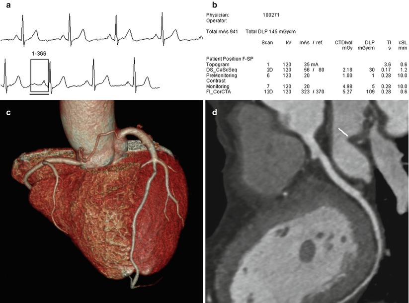
Fig. 21.8
High pitch technique (Flash-mode, Siemens). (a) In a patient with 58 bpm of heart rate. CT images are acquired in only one heart beat. (b) The total effective radiation dose of the CT examination including calcium scoring study is 1.86 mSv. (c, d) VRT and curved MPR images show good image quality from the one heart beat CT scan
A gapless z-sampling with a high pitch up to 3.4 enables complete coverage (120 mm) of the heart in a single heart beat within 300 ms duration.
Radiation dose can be reduced to 1 mSv and below.
Requires heart rates of less than 60–65 bpm.
21.3.5 Selection of Optimal CT Scan Protocol
Prospective ECG-triggered techniques should be used in patients who have stable sinus rhythm and low heart rates.
Retrospective ECG-gated techniques may be used in patients who do not qualify for prospective ECG-triggered scanning because of irregular heart rhythm or high heart rates or both.
If the cardiac anatomy or coronary artery disease is the main concern, prospective ECG-triggering technique is recommended.
If cardiac functional information is the main concern, retrospective ECG-gating technique is recommended with additional dose-saving technique.
If a large detector array of 256- or 320-slice is available, prospective ECG triggering is preferred.
21.4 Contrast Medium Injection
21.4.1 Optimum Level of Coronary Artery Enhancement
Greater intracoronary attenuation leads to higher diagnostic accuracy in the detection of coronary artery stenosis with MDCT.
Higher attenuation >500 HU → significant underestimation of stenosis in smaller vessels.
Lower attenuation <200 HU → poor coronary three-dimensional image.
The optimal vascular attenuation for stenosis detection in coronary CTA ranges from 250 to 350 HU.
21.4.2 Factors Affecting Coronary Artery Enhancement
Patient’s body size and cardiac output
Concentration of contrast medium
Contrast media with higher iodine concentration lead to higher attenuation in the coronary arteries.
The use of high iodine concentrations (e.g., 350, 370, or 400 mgI/mL) is recommended.
Contrast volume
As the speed of CT data acquisition increases, smaller amount of contrast media is required. Therefore, injection protocols must be adjusted to reduce unnecessary contrast agent (Table 21.2).
Table 21.2
Coronary CT angiography protocol adapted body mass index
BMI (kg/m2)
Dose of contrast material (mL)
Flow rate (mL/s)
<17.5
50
4.0
17.5–22.4
55
4.0
22.5–24.9
65
4.0
25–27.4
80
4.5
27.5–29.9
80
5.0
30–34.9
85
5.0
35–40
95
5.0
>40
105
5.0
With 64-slice scanners, the required contrast volume is as low as 50–70 ml.
Injection rate
If the contrast volume and concentration are kept constant, increased injection rate resulted in higher peak enhancement and shorter time to peak [14].
Injection rates of up to 4–6 mL/s via an antecubital vein are commonly used for coronary CTA.
21.4.3 Saline Chasing Technique and Injection Protocol
Uniphasic (monophasic) injection protocol
Uniphasic injection protocol uses contrast only.
Streak and beam-hardening artifacts (Fig. 21.9).
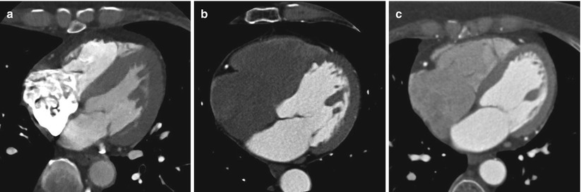
Fig. 21.9
Contrast injection protocols. (a) In uniphasic protocol, transaxial CT image shows a streak beam hardening artifact caused by non-diluted dense contrast media in the right atrium. (b) In biphasic protocol, shows excellent enhancement of left heart but weakness in the evaluation of the right heart due to complete washout of contrast medium. (c) In triphasic protocol groups, the right atrium and right ventricle were all enhanced uniformity, and the right ventricular septal endocardial contours are clearly delineated
Biphasic injection protocols
Pure (or undiluted) contrast media + saline bolus of 15–20 mL.
An injection rate of 4–5 mL/s as a saline chaser is optimal.
Reduce a streak and beam-hardening artifacts by clearing of contrast media in the superior vena cava and right heart.
Decrease attenuation in right ventricle → limited visualization of the ventricular septum (Fig. 21.9) or pathologic abnormalities, such as thromboembolism or tumors.
Biphasic concentration protocol: Initial undiluted contrast bolus + diluted contrast bolus
→ Improves right ventricular enhancement and reduces streak artifacts
Triphasic injection protocols
Initial pure contrast media bolus + 30 %: 70 % contrast-saline mixture + pure saline flush
The second bolus of contrast-saline mixture permits flushes out the high-density contrast media previously injected and also decreases streak artifacts in the superior vena cava (Fig. 21.9).
21.4.4 Contrast Timing Methods
The determination of the arrival time (or transit time) of the contrast media is crucial for consistent enhancement of coronary arteries and usually done using either test-bolus injection or automated bolus-tracking methods.< div class='tao-gold-member'>Only gold members can continue reading. Log In or Register to continue
Stay updated, free articles. Join our Telegram channel

Full access? Get Clinical Tree


