Coronary Arteries
Peter Lanzer
L.D. Timmie Topoleski*
*Coauthor: Principles of percutaneous coronary interventions
Since their introduction in the late 1970s, coronary interventions have gradually become technically less demanding and safer. This is primarily due to the introduction of low-profile high-technology products, stents, and microcatheter-based techniques. In fact, the greater facility of endocoronary instrumentation combined with the systematic use of guiding catheters for better steering and device manipulation in a highly vulnerable microenvironment has become a model approach for an increasing number of noncoronary endovascular interventions as well. Although the facility and quality of the instrumentation are important, the individual professional competence of the operator remains the most critical factor in the success of coronary interventions. Integral parts of professional competence are a thorough understanding of the principles of coronary image acquisition and interpretation, reliable risk and benefit definition for individual patients, and accomplished operational skills. To review the essentials of coronary interventions as they apply to real-life clinical practice, the traditional textbook approach of reciting the established medical facts and pronouncing treatment recommendations based solely on customary statistical evidence has been abandoned in this chapter. Instead, following a brief historical retrospective, practice-relevant principles of the coronary interventions have been reviewed. This review is systematic, starting with the description of the mechanical effects of coronary interventions, and includes the current requirements for interventional coronary competence, patient- and lesion-related risk factors, instrumentation, the basic structure of coronary interventions, complication management, and treatment strategies in standard clinical situations. Although a linear approach to reading the individual chapter may be preferable, each section is self-contained, and a study of selected topics of interest is fully acceptable for an advanced reader.
Retrospective
Following experimental and postmortem studies,1,2 the first intraoperative catheter-based coronary artery dilatation in a human was performed by Andreas Grüntzig, native of Dresden, Germany, in St. Mary’s Hospital in San Francisco in 1976.3 Subsequently, the first coronary intervention in a catheterization laboratory was performed by Grüntzig at the University Hospital Zürich, Switzerland, on September 16, 1977. The second procedure was also performed by Grüntzig, assisted by Martin Kaltenbach, at the University Hospital in Frankfurt am Main, Germany, on October 18, 1977, with the third and fourth procedures performed in Zürich and Frankfurt, respectively.4 Surgical stand-by on these procedures was provided by Ake Senning in Zürich and Peter Satter in Frankfurt am Main.
These first European experiences using the new technique of percutaneous transluminal coronary angioplasty (PTCA) were soon followed by procedures performed in the United States by Richard Myler at St. Mary’s Hospital, San Francisco, and Simon Stertzer at Lenox Hill Hospital, New York City. Between September 1977 and March 1980, a total of 377 PTCA interventions were reported (131 in Zürich, 67 in Frankfurt, 94 in San Francisco, and 85 in New York).5 By 1982 four institutions reported >300 cases (Zürich-Atlanta, Frankfurt am Main, San Francisco, and New York City).6
The first PTCA procedures were performed using 8F or 9F sheath and guiding catheter systems. Balloon catheters had a shaft diameter ranging from 0.5 to 1.25 mm (2F to 4F) and had
two lumina, one for contrast media injections and one for balloon inflation. Inflatable polyvinyl chloride (PVC) balloons ranged in size from 3.0 ÷ 10 mm to 3.8 ÷ 10 mm and were attached to the distal end of the catheter shaft. At the distal end of the shaft a short wire was attached for steering. The coronary artery was typically dilated at 5-bar pressures for 15 to 20 seconds. Because steering was difficult, stenoses of the left main and proximal coronary segments were dilated.7,8 These “fixed balloon” systems were manufactured by Schneider Meditang AG in Zürich at a rate of five sterile balloon catheters per week in 1977.9
two lumina, one for contrast media injections and one for balloon inflation. Inflatable polyvinyl chloride (PVC) balloons ranged in size from 3.0 ÷ 10 mm to 3.8 ÷ 10 mm and were attached to the distal end of the catheter shaft. At the distal end of the shaft a short wire was attached for steering. The coronary artery was typically dilated at 5-bar pressures for 15 to 20 seconds. Because steering was difficult, stenoses of the left main and proximal coronary segments were dilated.7,8 These “fixed balloon” systems were manufactured by Schneider Meditang AG in Zürich at a rate of five sterile balloon catheters per week in 1977.9
PTCA got off to a slow start and met mistrust and skepticism. However, following Grüntzig’s transfer to the University of Atlanta, in September 1980, and important improvements in technology, PTCA entered mainstream cardiology and has proceeded to achieve the unprecedented success that we witness today.10 Several important milestones and technical improvements shall be reviewed in this context.
In 1980 a movable 175-cm-long guidewire was introduced by John Simpson and Edward Robert at Stanford University that allowed better steering of the dilatation system, a technique later called balloon over the wire (OTW).11 Thus, the next generation of dilatation balloon catheters was manufactured using the coaxial double-lumen (Advanced Cardiovascular Systems, ACS) or eccentric guidewire lumen design (Schneider Meditang and United States Catheter and Instrument, Inc., USCI). The extra-long (300 cm) guidewire technique (“long wire”) introduced by Martin Kaltenbach in 1984 allowed exchange of dilatation balloon catheters without recrossing the target lesion.12 In 1986, extension (“docking”) wires that could be attached to the distal end of regular-length guidewires became available. Greater safety and the possibility of multiple balloon exchanges during the procedure markedly improved the use of PTCA, allowing more complete treatments of a greater number of lesions. A major extension of PTCA techniques followed the introduction of dilatation balloon catheters with a short guidewire lumen limited to the distal tip. Use of this monorail or rapid-exchange system (designed by Tasilo Bonzel, University Freiburg/Breisgau13) made possible multiple rapid balloon exchanges using regular-length guidewires, which markedly accelerated the time required to perform coronary interventions.
Perhaps the most significant event in the short but eventful history of PTCA was the introduction of coronary stents by the groups led by Ulrich Sigwart14 and Joel Puel15 in 1987. Coronary stent implantation primarily employed as a “bail-out” in selected patients after unsuccessful PTCA has drastically changed the basic approach to catheter-based coronary therapy in the course of less than two decades. Stenting has led to a reduction in restenosis rates; an improved clinical outcome, and the greater safety of endocoronary interventions, which in turn have recently opened up a new era in pharmacotherapy16 and stent technology; the use of bioabsorbable materials17 promises to rapidly transform mechanical endovascular “plumbing” into biological vessel repair. However, it is important to remember that the wide clinical acceptance of intracoronary stenting only became possible after the thrombotic and bleeding complications have been brought under control through the use of powerful ADP receptor and GPIIb/IIIa receptor inhibitors (for review, see references 18 and 19).
In addition to conventional “plain old balloon angioplasty” (POBA) and stent-supported PTCA, several other techniques of coronary artery revascularization have been introduced into clinical practice. In 1985 John Simpson, of Stanford University, introduced directional coronary atherectomy (DCA) to permit debulking of protruding components of atherosclerotic plaques.20 In 1987 another debulking technique, high-speed rotational atherectomy, was introduced by Kenneth Kensey and John Nash, from the Michael Reese Hospital in Chicago.21 Excimer laser coronary atherectomy (ELCA), which allows partial plaque removal and modification by evaporation of soft tissue components, was introduced in1989 by Frank Litvack, from Cedars-Sinai Medical Center, Los Angeles.22 Finally, the introduction of intracoronary radiation therapy (brachytherapy) represented an important step toward efficacious treatment of coronary restenotic lesions.23
This brief review of memorable developments in endocoronary therapy would remain incomplete without several important milestones in acute coronary revascularization therapy being mentioned. The use of selective intracoronary fibrinolysis was introduced into broad clinical practice by the group led by Peter Rentrop, University of Göttingen.24 The subsequent systemic application was introduced by Rolf Schröder and his group at the Free University of Berlin in the early 1980s.25
Principles of Percutaneous Coronary Interventions
Atherosclerosis is considered a complex biological response, primarily inflammatory in nature, of the vessel wall and blood constituents to vessel wall injury (“response-to-injury” hypothesis).26 Following decades of study, proposals have been made for the temporal evolution, classification, and nomenclature of atherosclerotic lesions.27,28,29 Similarly, many of the biological events leading to the progression and rupture of atherosclerotic plaque have been elucidated (for review, see chapter 1). In itself remarkable and noteworthy is the long and arduous path necessary to turn an initial observation of the cause-and-effect relationships between thrombus and myocardial infarction30 and between thrombus and plaque rupture taking multiple stages31,32,33,34,35 into clinically accepted facts36 and design of causal therapy.24,25 Whereas pharmacotherapy primarily aims at removing the last link in a long chain of events, that is, thrombosis and thrombus formation and more recently plaque pacification, the goal of angioplasty and other catheter-based techniques is the removal or modification of hemodynamically relevant and unstable atherosclerotic lesions. The principle behind angioplasty is the acute mechanical stretch and subsequent biological remodeling of the vessel wall.
Mechanical Response of Coronary Artery Lesions: Geometry, Boundary Conditions, and Material Properties
Predicting the mechanical response of any material subject to external forces requires a full understanding of three fundamental elements: (i) the geometry of the material, (ii) the boundary conditions, which include not only the forces applied, but also the other constraints on the material, and (iii) the
mechanical properties of the material. This is also true for predicting or understanding the response of an atherosclerotic lesion subject to balloon inflation during angioplasty. A discussion of how each of these elements influences the deformations of a body will be useful before specific topics regarding lesion deformation are examined.
mechanical properties of the material. This is also true for predicting or understanding the response of an atherosclerotic lesion subject to balloon inflation during angioplasty. A discussion of how each of these elements influences the deformations of a body will be useful before specific topics regarding lesion deformation are examined.
Although the geometry of lesions may be the most accessible of the three elements required to predict mechanical behavior, it is by no means easy to determine. Histological reconstruction of an atherosclerotic lesion is useful for continued research on the mechanical effects of angioplasty, but is of little immediate use to the patient. Although a technique such as intravascular ultrasound (IVUS) provides potentially useful images of an atherosclerotic lesion, the use of ultrasound to determine an exact geometry and tissue composition (for example, the thickness of a calcified lesion) requires knowledge of the material properties related to ultrasound backscatter, the speed of sound in the different materials, and the boundary-wave reflection and transmission characteristics (which depend on the acoustic impedance of the different materials). If the plaque contains two or more distinct tissues (i.e., if it is partly fibrotic and partly calcified), then the reconstructed ultrasonic image may not show the exact geometry (and thus not lead to a correct judgment) if the ultrasound properties of the materials are not known.
To illustrate the role that geometry plays in a material’s response to externally applied loads, consider the simple analogy of a soft substance sandwiched between two harder plates, such as jam or jelly between two crackers. If the jam layer is thin and the crackers practically touch, then the sandwich responds almost like two crackers alone. If the jam layer is thick, then the sandwich initially responds almost as jam alone and the jam is extruded as the crackers are pushed together. Thus, without knowing the exact geometry and tissue composition of the lesion, the prediction of the material’s (i.e., the lesion’s) response to loading will likely be invalid.
Because plaque is generally irregularly shaped and it is irregularly embedded within the underlying vessel wall, the forces applied by a smooth dilatation balloon will be irregularly distributed and highly complex. In some engineering systems, simplified models of applied forces and geometry can lead to usable designs or solutions, often “averaging out” the effects of material inconsistencies and irregular geometries and forces. In such cases, however, local effects of the irregularities do not greatly influence the overall behavior of the material. In the case of atherosclerotic lesions, however, it is likely that local geometric effects play an important role in determining how and when a lesion will rupture.37,38 Because understanding the detailed (local) response of the plaque is essential for determining how the plaque will respond, researchers such as Holzapfel et al.39,40,41 use intricate numerical simulations, such as the finite-element method, to investigate plaque responses at the local level.
The finite-element method (FEM, also known as finite-element analysis or FEA) is a powerful numerical technique for predicting stress and strains in a body under a system of loads (in fact, FEM can also be used for many applications, including fluid flow and magnetic fields). The method is based on representing an irregularly shaped body (such as an atherosclerotic plaque) by a network (called a “mesh” or “grid”) of regularly shaped “elements,” usually rectangles or triangles (Fig. 8.1). Both two-dimensional and three-dimensional analyses are applied to many problems. For an FEM analysis, the geometry of a lesion may be obtained from histological sections. The full three-dimensional geometry can be reconstructed from sequential histological slices. Equations for stress and strain are solved on an element-by-element basis, and then the stress and strain fields, which provide the prediction of the material’s response to loading, are reconstructed for the entire body. Although FEM is invaluable for analysis, it remains only a model of the physical system. Its usefulness as a predictive tool depends on its accuracy in reproducing the geometry, boundary conditions, and material properties of the object being analyzed. To properly interpret FEM results, and thus obtain useful information, it is essential that FEM users, especially when studying complex systems such as biological tissues, understand the limitations of the method and interpret the results accordingly. For any model to be treated as a “black box,” where the results are taken as absolute fact without users having an understanding of the limitations of the model, can lead to erroneous and even dangerous conclusions.
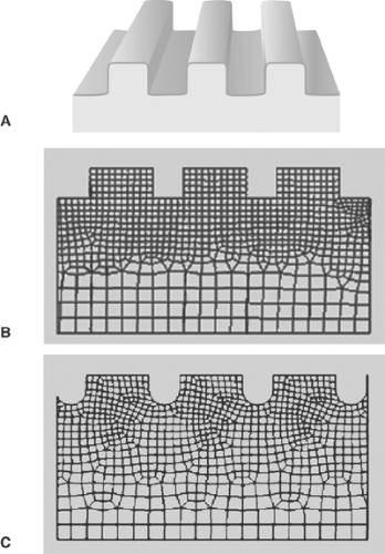 FIGURE 8-1. Examples of finite elements. A: 3D rendering of simple square channels in a material. B: Head-on view of the same material, broken into many discrete elements (the finite element “mesh” or “grid”). C: Channels with a different cross section, showing a different finite element. |
In the case of balloon angioplasty, forces are imparted to the lesion by the balloon catheter. Balloon catheters are designed to open up or to dilate occluded or stenotic vascular segments. Inflating small longitudinal balloons filled with fluid—a mixture of normal saline and contrast media—under high pressure generates radial forces that are exerted onto the vessel walls,
causing expansion of the dilated segment associated with loosening of the vessel wall architecture, limited tears of the subintimal layers, and mainly longitudinal plaque redistribution.
causing expansion of the dilated segment associated with loosening of the vessel wall architecture, limited tears of the subintimal layers, and mainly longitudinal plaque redistribution.
Boundary conditions include all of the forces applied to a material or structure, and all constraints on the material’s deformation. Consider, for example, a heavy box placed in the center of a round table. The table is subject to a force—a distributed load—at each point where the box contacts the table and the center of the table sags toward the ground. The legs of the table are presumably in contact with the floor, which prevents the table legs from moving further toward the ground. In engineering terms we may say that the vertical displacement of the table legs is zero. In this illustration, there are examples of both load and displacement boundary conditions (the effect of the contact of the mass of the box, and the effect of the contact of the table legs with the floor, respectively). It becomes much more difficult to predict how much the table would sag if there were different springs or flooring types under each table leg, or if the loads on the table top were uneven and not centered on the table.
A balloon catheter is fairly symmetric and cylindrical when inflated. The radial force applied to the vessel (lesion) wall, at a first approximation, is similar to an internal pressure acting on the vessel wall. An internal pressure, however, is uniform at every point and acts perpendicular to the surface; the forces imparted by the balloon to the vessel wall are, in contrast, probably not uniform because of the irregular contact surface and heterogeneous composition of the lesions.
The lesion sits on or is embedded in the underlying vessel wall. The vessel wall thus constrains the movement or deformation of the lesion, but since it itself is not rigid, it will deform under loads. In this case, the mechanical properties of the underlying vessel will define a boundary condition on the lesion. If the vessel is included explicitly in an analysis, then the geometry and material properties of the vessel must be known. The tissue surrounding the vessel is then the source of the boundary condition(s). If the vessel is in contact with or embedded in muscle tissue, for example, then the boundary conditions, and hence the vessel response to loads, will change depending on whether the muscle is relaxed or contracted.
A further complexity of enormous import that may be included in the discussion of boundary conditions is the way that different tissue types in a diseased vessel—plaque cap, underlying lesion, modified media, vessel, for example—are connected. The interfaces between the materials and the manner in which those interfaces behave will have a pivotal influence on plaque response. The influence is especially obvious when plaque dissection, or “lift-off” from the vessel wall, is considered. Little is known of the behavior of lesion material interfaces, and this knowledge is essential for understanding critical responses of lesions as well as a lesion’s vulnerability to rupture or dissection.
Even sophisticated state-of-the-art computer analyses of the responses of atherosclerotic lesions to the forces of balloon angioplasty are limited by the extent to which the material properties of the lesions and underlying vessel walls are known. Without knowledge of the material properties, accurately predicting lesion response is impossible even if the geometry is known precisely. We gain little if we know the exact thickness of the jam in the previous example, but assume or believe that it behaves like hard cheese. Few investigators have accepted the challenges of studying the mechanical properties of atherosclerotic lesions.42,43 Experimental studies to date show that most lesions share some general characteristics: for example, the mechanical responses are nonlinear and exhibit hysteresis (Fig. 8.2), that is, they behave differently when loading and unloading. It is also clear that detailed responses are lesion specific. The studies also concluded that relatively little is known about the mechanical properties and that much additional work is necessary to develop an understanding of lesions’ responses.
There are, of course, many limitations inherent in determining the material properties of biological tissue. Since material properties must be determined by mechanical testing, the mechanical testing of lesion response to forces is performed primarily on dissected vessels and lesions. The ex vivo specimens are usually removed from their natural loading environment (the pulsatile blood flow) for several hours to perhaps nearly 2 days before testing. It is well documented that healthy blood vessels undergo a “relaxation” when they are removed from their loading environment. Researchers usually perform a series of loading-unloading cycles, called “preconditioning,” to return the specimens, in theory, to their physiological state. The specimens are subject to a number of loading-unloading cycles sufficient to demonstrate that the mechanical response repeats from one cycle to the next, and are then considered preconditioned. A critical assumption, however, is that the vessels have been returned to their physiological state since that state is unknown.
An example of an investigation of plaque’s mechanical properties is found in a series of studies by Topoleski, Salunke, Humphrey, and Mergner.44,45 Isolated plaques from diseased arteries were dissected and tested in tension and unconfined compression. The specimens were subjected to 15 loading-unloading cycles (preconditioned), allowed to rest for 15 minutes, and then subjected to another 15 loading-unloading cycles. The relationship between the responses to the first loading protocol and those to the second proved to be a function of the type of lesion (atheromatous, fibrous, or calcified) (Fig. 8.2). More recently, Holzapfel et al.43 performed tensile tests on isolated components of diseased vessels (plaque cap, intima, media, adventitia) to investigate their mechanical properties. Their results further underscore the highly complex character of the mechanical response of a diseased artery. It remains imperative to develop an understanding of the mechanical properties and responses of atherosclerotic tissue.
Isolating lesions for mechanical testing may provide insights into the local behavior of the lesions, but in vivo the lesions are usually intimately entwined with the underlying vessel tissue. Today there is no way to accurately predict or understand the interaction between the lesion and underlying tissue, and therefore no way to predict the response of the lesion-tissue system to the forces imparted by balloon angioplasty. Nonetheless, it is essential to understand the behavior of isolated lesions and tissue segments as a first step toward understanding the response of lesions in the context of diseased vessels with different pathologies.
The geometry, boundary conditions, and material properties interact to produce a unique stress state in a lesion. Only by understanding the detailed contributions of each can we truly understand how a specific lesion will respond to forces applied during angioplasty. A generalized model of lesion
behavior, however, can be described in a relatively straightforward manner.
behavior, however, can be described in a relatively straightforward manner.
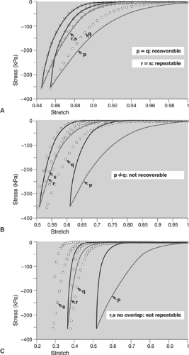 FIGURE 8-2. Ex vivo studies of mechanical properties of atherosclerotic plaques with different tissue composition. In this series of experiments, dissected plaques were subjected to 15 cycles of radial compressive loading (phase I), and then allowed to “rest” for 10 min. The specimen was subjected to a second set of 15 cycles (phase II). In each figure, only the first and 15th cycle for each phase are presented for clarity. In each case, the specimens were classified by mechanical behavior before histological analysis. Curve p is the first loading cycle of the first phase, and r is the 15th loading cycle of the first phase; curve q is the first loading cycle of the second phase, and s is the 15th loading cycle of the second phase. A: Curves p and q are very close on loading and overlap during unloading. This behavior was termed “recoverable,” indicating the specimen’s apparent recovery to its initial state (i.e., from curve r to curve q) during the rest period. Also, curves r and s overlap (the 15th cycles for each phase), which was termed “repeatable,” indicating that the stress-stretch behavior was consistent (or had reached a state of equilibrium) for each phase by the time the 15th cycle was reached. B: p and q do not overlap, hence the specimen did not recover during the rest period; however, curves r and s overlap, indicating that although the specimen did not recover, the behavior apparently reached the same state of equilibrium by the 15th cycle for both phases. C: Neither p and q, nor r and s showed any relationship, indicating that the specimen neither recovered nor reached a state of equilibrium after 15 cycles. Histological analysis showed that the behavior represented in A was associated with calcified plaques. The calcification may have contributed an elastic component to the material that allowed the recovery. The behavior in B was associated with fibrous plaques. The first loading phase apparently compressed the plaque beyond its ability to recover in the experimental time frame, but the plaque reached a state of equilibrium. The behavior in C was associated with atheromatous plaques. It is possible that material from the viscous or liquid core was forced out of the fibrous tissue network during the entire test, and thus the plaques neither recovered nor reached a state of equilibrium. |
As a result of the forces applied by the balloon catheter, the lesion and vessel wall undergo radial compression, which generally acts to compress the lesion and wall thickness. In addition to compressing the vessel wall, the forces exerted by the dilatation balloon tend to expand the vessel diameter, creating circumferential tension (or “hoop stresses”) in the vessel wall. By expanding a relatively small length of a vessel, defined by the length of the balloon, longitudinal tension is also generated, especially near the shoulders of the balloon catheter. Movement of the balloon during inflation may also result in shear forces being applied to the lesion (vessel) wall surface. Even this simple analysis describes a complex, multifaceted loading of the vessel wall from a balloon catheter, resulting in complex stresses and deformations, or strains, in the expanded vessel (for example, see reference 46).
The goal of angioplasty is to create a permanent deformation (leading to an expanded lumen) of either the vessel wall or the atherosclerotic lesion, or both, without producing collapse of the wall.
Regardless of the complexity of the deformations, they are reversed if the deformations are “elastic.” Permanent (or “nonelastic”) deformations, such as fracture or rupture of the lesion, or permanent deformations from other mechanisms, are necessary for the shape of the lumen to change. Mechanisms that are responsible for permanent deformations, and hence the open lumen, are not well understood. For example, microcracking of a calcified lesion is a possible mechanism for permanent deformation (this may be analogous to bending a “green” twig from a tree: the twig will develop cracks and remain bent, but will not snap apart like a dried twig). “Overstretching” of the plaque or the vessel wall is another way of saying “nonelastic” or permanent deformations. The local mechanisms by which overstretching keeps the lumen of a vessel open are not known: This is in contrast to the mechanisms for plastic deformation of a metal, for example. Knowledge of the plastic deformation mechanisms in metals has allowed materials scientists and engineers to use those mechanisms advantageously to design better materials for specific applications. A better understanding of the mechanisms by which an occluded blood vessel retains an expanded lumen following dilation would probably lead to techniques for improving the outcomes of angioplasty.
If the lumen stays open by creating nonelastic deformations, residual stresses are developed within the material. Neither the extent nor the location of the residual stresses is known, nor how they may affect the subsequent (long-term) response and any possible reocclusion of the vessel.
Furthermore, even though the forces applied to the lesion or vessel wall through the balloon catheter are ostensibly radially compressive, the response of the lesion may not be compressive. For example, a theory of mechanics known as “beam on elastic foundation” predicts the behavior of one material (the “beam”) as it undergoes externally applied loading while it sits on another material (the “elastic foundation”) (see for example the treatment by Haslach and Armstrong47) Although beam on elastic foundation may not be a completely accurate model of the lesion-vessel wall system, the theory illustrates an important result that we may not overlook. Under certain combinations of geometry, boundary conditions, and compressive loading, parts of the beam (the lesion) will, in fact, tend to lift away from the underlying vessel wall (Fig. 8.3). Consider again the analogy of a green twig: If someone steps on a green twig lying, for example, on concrete, then the concrete fully supports the twig and nothing much happens. The twig may not even respond or deform. In contrast, if the twig is lying on compliant soil, then stepping on the center of the twig can cause the ends of the twig to lift off the ground. Similarly, if the ends of a lesion are pulled away from the underlying vessel wall, then the result might be further rupture or perhaps thrombosis in the resulting fissure. Thus, if we apply the beam on elastic foundation theory, it is vital for us to understand how the relationship between the size of the lesion and the size of the balloon (the balloon “coverage”) can affect the response of specific lesions in specific vessels.
In current clinical practice, a stent is generally deployed at the site of the occlusion after balloon expansion. A stent acts as a permanent mechanical barrier to the potential elastic “recoil” of the open lumen, regardless of whether the recoil originates in the plaque or the underlying vessel. The stent is essentially a “retaining wall” to keep the lumen in place. It in fact creates new boundary conditions on the lesion. The mechanics following stent placement are also not well understood, although it is clear that residual stresses are present, probably in both the plaque and the underlying vessel. The stents are subject to the same cyclic loading as the lumen (pulsatile loads) and may be subject to fatigue failure in the long term.
Through mechanical intervention, it is possible to change the geometry of the lesion, reopening the lumen for improved blood flow. Given our current knowledge base, however, the complex geometry, boundary conditions, and material properties of a diseased vessel make it practically impossible to make detailed predictions of vessel responses. Once these elements
are known, however, we must still create clinical protocols to specifically target and activate mechanisms that will keep the lumen open, and not activate those that are potentially harmful, such as changes in lesion geometry that could lead to renarrowing and thrombus formation.
are known, however, we must still create clinical protocols to specifically target and activate mechanisms that will keep the lumen open, and not activate those that are potentially harmful, such as changes in lesion geometry that could lead to renarrowing and thrombus formation.
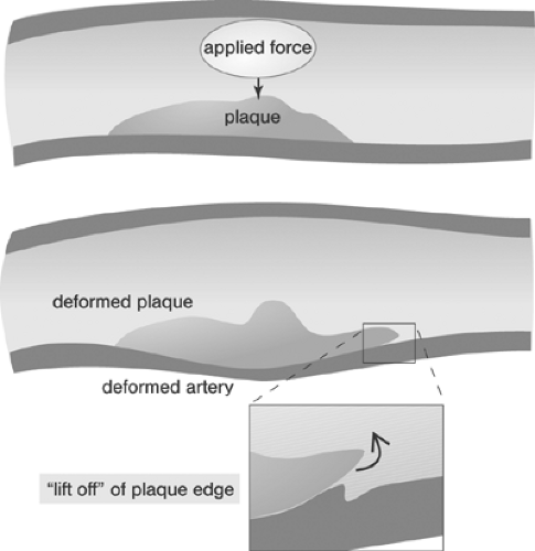 FIGURE 8-3. (Top) A concentrated force applied to an irregularly shaped plaque. The deformations would be analogous for a more distributed load, for example, from the surface of a balloon. (Bottom) The loaded configuration (deformation). (Inset) How the ends of the dissimilar materials—plaque and vessel wall—may tend to separate. |
Mechanical Effects of Angioplasty
The local changes in tissue response that lead to permanent deformations, and hence successful angioplasty, are a specific subset of the lesion’s material properties. In engineering materials, for example, the yield stress of a material marks the onset of permanent deformation; it is a property specific to each material that must be determined experimentally.
Grüntzig assumed plaque compression to be the principle mechanism of coronary angioplasty (“footprints in the snow”). Although initial studies performed by Kaltenbach at the Mayo Clinic in 1978 seemed to confirm this hypothesis,48 later studies showed that the stretching of the vessel wall associated with plaque rupture and plaque redistribution are the main mechanisms of stenosis dilatation.49,50 The combination of focal plaque rupture, wall dissection, and radial and longitudinal wall stretch has been documented as being an important sequelae of angioplasty in both native coronary arteries and venous coronary bypass vessels.51,52,53 Plaque compression and distal embolization of plaque components were considered less important components of dilatation. Unwanted results of coronary artery dilatation associated with angioplasty include complete destruction of the vessel wall architecture, extensive dissections, thrombus formation, vessel closure, and perforation. Successful angioplasty activates those mechanisms that retain the open lumen while avoiding the detrimental results.
It is poorly understood how the expansion of the balloon is translated into stresses and strains in the tissue, how much a specific tissue deforms, and whether the deformation is permanent or transient. Despite the need for more extensive and detailed research, some basic and general concepts can be developed from simple analyses. As a starting point, the principal stresses developed in the vessel wall may be calculated using a simplification of Laplace’s equation for circumferential (hoop) σθ, radial σr, and longitudinal (axial) σl stresses:


 where p is the internal pressure acting on the vessel wall, d is the mean diameter of the vessel, and t is the mean thickness of the vessel wall. According to the equations, both the radial and the hoop stresses are greater than the longitudinal stress. If the balloon is just at its full extension and is pressing uniformly against the vessel wall (i.e., applying uniform pressure to the vessel wall), then we can estimate the stresses in the vessel by


 where pb and db are the balloon inflation pressure (N/cm2) and the balloon diameter at the balloon inflation pressure pb (cm), respectively. However, these relationships will hold only if the internal pressure in the balloon and the balloon diameter are good approximations of the pressure on the vessel wall and the diameter of the vessel. Since the balloon is opening an obstructed or occluded vessel and its size is adjusted to the nominal size of the adjacent nonstenotic coronary artery segment, allowing reasonably accurate matching between balloon and vessel diameters, the pressure-diameter relationship is likely to remain approximately linear. However, the pressure-diameter relationship within the balloon may become nonlinear because of significant deformations of the inflated, not fully noncompliant balloons, such as in rigid, highly irregular stenoses. When the pressure-diameter relationship is nonlinear, the pressure in the balloon pb may not be a good approximation of the pressure on the vessel wall.
Several important conditions must be met for Equations 1 and 2 to apply to angioplasty. First, the material under pressure (i.e., the blood vessel wall with or without plaque) must be linear, homogeneous, elastic, and isotropic. Note that here, in engineering terms, the meaning of elastic is not that commonly understood in the medical literature. Elastic means that material will return to its original state once the load that causes a deformity—for example, an artery stretched by internal pressure—is removed; it does not necessarily mean that the material is “stretchy” (extensible) or rubbery. Homogeneous means that the mechanical properties and the mechanical response to applied forces are the same everywhere in the material. If the nature of the material changes, for example, the composition changes from area to area, then the material is likely not to be homogeneous (described as “inhomogeneous”). Isotropic means that the material properties as well as the mechanical response to applied forces are the same regardless of the direction in which the forces are applied. Materials with preferred fiber orientations, for example, have different material properties in different directions (e.g., along the fiber direction vs. perpendicular to the fiber direction), and are therefore not isotropic (described as “anisotropic”). In fact, blood vessels are not linear, homogeneous, or isotropic; consequently, Equations 1 and 2 give only a very rough, first-order estimate of the stresses in the blood vessel.
Another complication is that Equations 1 and 2 hold only for what is termed a “thin-walled” cylinder, where the thickness is at most 10% of the vessel radius. The equations assume that the stresses are uniform throughout the vessel wall, which is only true when the wall is thin and homogeneous (in fact, the stresses may begin to vary when the wall is as little as 3% to 5% of the radius).
If the vessel wall is “thick,” that is, >10% of the luminal radius, as is the case in many blood vessels, then a different theory is used to predict the stresses:
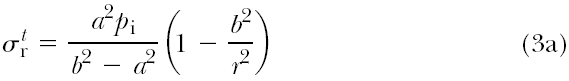
 where a and b are the inner radius and outer radius of the vessel, respectively, pi is the internal pressure (assuming there is
only internal pressure acting on the vessel), and r is the radius of interest within the vessel wall (e.g., at the center of the vessel wall, r = a + (b – a)/2).
only internal pressure acting on the vessel), and r is the radius of interest within the vessel wall (e.g., at the center of the vessel wall, r = a + (b – a)/2).
Both sets of equations were originally derived for a cylinder made of an engineering material, such as a metal, under internal pressure. The strains, or deformations, of such pressurized cylinders are very small. For the equations to be accurate, the strains must be small, for which “small” means less than a 10% change. Because the deformations of a blood vessel, either under blood pressure or during balloon angioplasty, may not be small, the equations have limited predictive power.
The system of a vessel wall and an atherosclerotic lesion is certainly nonelastic, inhomogeneous, and anisotropic. In addition, the irregular geometry of the occluded vessel results in complex loading over the lesion surface. Given the irregular geometry, the complicated system of applied loads, and the complex nature of the material properties, understanding the lesion’s response to the balloon angioplasty procedure, and the mechanisms of permanent deformation that are activated during it, is a formidable problem. This prompted modern biomechanical studies of stresses in blood vessels. One of the first and widely applicable theories was developed by Fung et al. in 1979.54 The complex treatment of stresses in nondiseased vessels is well summarized by Humphrey.55 More recent, and more involved, theories of stresses in nondiseased vessels are found, for example, in Gleason et al.56 and Haslach.57
The limitations of the pressure vessel theory can be illustrated by a relevant example. Based on the thick-walled model, overstretching the vessel by 10% of its diameter is associated with an increase in circumferential stress of approximately 10%. Based on the more advanced and physiologically reasonable model by Fung et al.,54 the same increase of 10% in diameter can result in a 23% increase in stress.1 Further overextension, to 30% of vessel diameter, for example, results in a 30% stress increase based on the thick-walled model but in 116% increase according to the model of Fung et al. Neither model takes into account the irregularities of an atherosclerotic lesion; the models both assume that the vessel is not diseased. The presence of disease complicates calculations of the stress and strains in the lesion and the vessel. It must be emphasized that increasing the balloon pressure, regardless of the model used, increases the associated stresses, markedly increasing the risk of rupture. It is important that investigations of balloon induced stresses be continued in order to reduce the potential for plaque rupture. Furthermore, and perhaps more pertinent to angioplasty, none of the models discussed is able to predict the stress at which a permanent deformation mechanism is activated.
Following balloon deflation, the plastic and elastic forces within the coronary artery wall—antagonistic by their very nature—become operative. Lesion or vessel material that has plastically deformed remains in the deformed shape. In contrast, adjacent material that has only been elastically deformed, and which would return to its original shape in the absence of any constraint, is prevented from doing so. Thus, new residual stresses are created within the lesion and the vessel. The consequences of such induced residual stresses in the diseased vessel are not known. They may include initiating or mediating biological responses, such as remodeling of the vessel wall or endothelial cell proliferation, and long-term mechanical responses, such as rendering the lesion susceptible to future rupture caused by lesion fatigue under applied pulsatile loads.
Mechanical Effects of Stent Implantation
The inflation of balloons with crimped stents—in contrast to conventional balloons—causes the vessel walls to become permanently distended at the stented segments. Neglecting a certain amount of elastic recoil allowed by the stent, the forces exerted against the walls remain operative until termination of the vessel’s remodeling process. At the edges of the stent, there is a sharp change in the stresses affecting the vessel, causing a major redistribution of stresses between the stented and nonstented adjacent segments. In many engineering systems, areas of high stress gradients (where the stress changes quickly over small distances) sometimes result in stress concentrations and are vulnerable to failure or unwanted deformations. Such stress concentrations may cause the proliferation of endothelial cells observed in some stented vessels at the transition points. However, the relationships between the stresses on the vessel and the biological responses are not known.
Biological Effects of Angioplasty and Stent Implantation
Arterial vessel wall remodeling is a result of biological adaptation at atherosclerotic plaque sites.58 Based on morphometric measurements, three basic responses to an increasing plaque burden can be distinguished: expansion, lack of change, and shrinkage, corresponding to positive, absent, and negative remodeling, respectively. Using IVUS, the remodeling ratio (RR) is defined as the ratio of the external elastic membrane (EEM) area at the lesion site to the EEM area at a defined proximal reference site.59 Positive remodeling of the culprit lesions’ sites is associated with unstable coronary presentation60 and has been observed more frequently in fibrofatty lesions.61 Following angioplasty, serial IVUS data show a healing defect associated with positive, intermediate, or negative remodeling. Dilatation sites with the largest initial gain showed a greater propensity for restenosis on follow-up at 1 to 6 months.62 Implantation of a bare metal stent (BMS) effectively prevents remodeling at the implantation sites but it does not fully prevent an in-stent restenosis due to myointimal hyperplasia. Positive peri-BMS remodeling appears to be associated with a lower incidence of in-stent restenosis (see reference 63; for review, see chapter 1).
Percutaneous Coronary Interventions
Percutaneous coronary intervention (PCI) represents first-line emergency treatment in patients with ST segment-elevation myocardial infarction who present early (up to 12 to 24 hours) following the onset of symptoms and in the majority of patients with non-ST segment-elevation myocardial infarction. Furthermore, elective PCI represents an important therapy option in
patients with chronic coronary artery syndromes. In the subsequent sections, selected principal issues relevant to the clinical practice of PCI will be reviewed. However, a fully comprehensive review of the available literature neither has been intended nor will be provided.
patients with chronic coronary artery syndromes. In the subsequent sections, selected principal issues relevant to the clinical practice of PCI will be reviewed. However, a fully comprehensive review of the available literature neither has been intended nor will be provided.
Relevance
Since their introduction in 1977 and 1987, respectively, percutaneous transluminal coronary angioplasty (PTCA), also termed in colloquial usage plain old balloon angioplasty (POBA),3,4 and stent-supported angioplasty, also termed in a broader sense percutaneous coronary intervention (PCI),14,15 have become increasingly important strategies in routine management of patients with acute and chronic syndromes of coronary artery disease (CAD). Although representative figures of the number of procedures performed are difficult to obtain, a few selected examples easily illustrate the astounding proliferation of catheter-based CAD treatments in Western countries (Tables 8-1 and 8-2, Figures 8-4 8-5 8-6).64,65 However, the absolute number of procedures performed in the West is likely to appear modest when compared with future data from the new rapidly growing economies of China and India.
Evidence
The efficacy of coronary artery bypass graft surgery (CABG)66 and its superiority over medical treatment in patients with CAD have been documented (for review, see references 67 and 68). Figures 8-7 and 8-8 show the overall benefits of CABG surgery and those derived by selected subgroups of patients.
Similarly, the efficacy and superiority of PTCA3,4 over medical treatment in patients with CAD has been demonstrated in terms of relieving angina and improved quality of life (for review, see reference 69). Comparisons of PTCA and CABG during the prestent era showed no statistical difference in mortality and combined cardiac outcomes (cardiac death and nonfatal myocardial infarction). However, patients randomized to CABG were less likely to experience postprocedural symptoms and were less likely to require subsequent revascularization (Table 8-3).67 Among subgroups, PTCA was superior to CABG in patients with single-vessel and two-vessel disease without high-grade (≥95%) left anterior descending (LAD) disease. In patients with three-vessel and patients with two-vessel disease and ≥95% LAD disease, CABG was superior as shown in Figure 8-9 (for review, see reference 67).
Comparisons between bare metal stent, BMS-supported angioplasty and CABG disclosed trends similar to those observed in PTCA and CABG studies; however the gap in prevention of reinterventions on follow-up and total event rates has narrowed (Table 8-4).67 Results of the more recent Arterial Revascularization Therapies Study (ARTS) randomized trials showed comparable results for BMS-supported angioplasty and CABG in terms of mortality and incidence of stroke and myocardial infarction, but superiority of CABG in terms of the need of repeat revascularization and recurrence of angina on a 5-year follow-up in patients with multivessel disease (Fig. 8.10).70 These results have been confirmed by the Argentine Randomized Study: Coronary Angioplasty with Stenting Versus Coronary Bypass Surgery (ERACI II) trial.71
TABLE 8-1. Estimated Number of Percutaneous Transluminal Coronary Angioplasty (PTCA) Procedures Performed in the United States 1995–2000 | |||||||||||||||||||||
|---|---|---|---|---|---|---|---|---|---|---|---|---|---|---|---|---|---|---|---|---|---|
| |||||||||||||||||||||
TABLE 8-2. German Registry of Percutaneous Coronary Interventions (PCI) 1984–2002 | |||||||||||||||||||||||||||||||||||||||||||||||||||||||||||||||||||||||||||
|---|---|---|---|---|---|---|---|---|---|---|---|---|---|---|---|---|---|---|---|---|---|---|---|---|---|---|---|---|---|---|---|---|---|---|---|---|---|---|---|---|---|---|---|---|---|---|---|---|---|---|---|---|---|---|---|---|---|---|---|---|---|---|---|---|---|---|---|---|---|---|---|---|---|---|---|
| |||||||||||||||||||||||||||||||||||||||||||||||||||||||||||||||||||||||||||
Comparison of PTCA and BMS-supported angioplasty has shown the superiority of stenting in terms of reducing the number of major adverse cardiac events (MACE), which was higher in high-risk patients, and restenosis rates. These studies were not powerful enough, however, to determine the impact on mortality and the subgroup effects (Fig. 8.11) (for review, see reference 72).
Following the introduction drug-eluting stents (DESs), their superiority over BMS has been demonstrated in a number of trials primarily in terms of the in-stent restenosis rates (Figs. 8-12, 8-13). The superiority was not shown convincingly for mortality and nonfatal myocardial infarction (for review, see reference 72). A more recent review of the data confirms the evidence (for review, see reference 73) and suggests differences in outcome with different drug-eluting agents.74,75
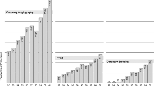 FIGURE 8-4. Coronary angiograms, percutaneous transluminal coronary angioplasty (PTCA), and coronary stenting from 1992 to 2001 in Europe in thousands of procedures. (Modified from Togni M, Balmer F, Pfiffner D, et al. Percutaneous coronary interventions in Europe 1992-2001. Eur Heart J. 2004;25:1208-1213.) |
Trials comparing DES-supported angioplasty and CABG, such as SYNergy, SYNTAX, and ARTS II, are underway and will provide more definite evidence regarding the current state of the art interventional and surgery strategies for elective coronary artery revascularization in different patient populations.
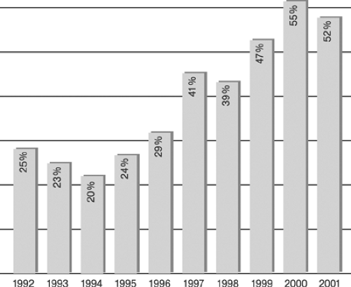 FIGURE 8-5. Ad hoc percutaneous transluminal coronary angioplasty (PTCA) from 1992 to 2001 in Europe (percent of total). (Modified from Togni M, Balmer F, Pfiffner D, et al. Percutaneous coronary interventions in Europe 1992-2001. Eur Heart J. 2004;25:1208-1213.) |
Training
Initially, the process of learning angioplasty was an informal matter of learning by doing. This corresponded to the grass-roots style of the courses organized by Grüntzig in Zürich and Atlanta in the late 1970s and early 1980s, rather than being based
on theory and structured teaching. Since the mid-1980s curricula and formal training requirements have been successively introduced in angioplasty and interventional cardiology. Current fellowships in interventional cardiology typically require a minimum of 1 year of training following a formal training in cardiology. For example, in the United States the current guidelines for training in interventional cardiology stated by the American Board of Internal Medicine (ABIM) 76 include “a minimum of 250 therapeutic interventional cardiac procedures during 12 months of accredited interventional cardiology fellowship training.” Trainees are required (selected excerpts) to:
on theory and structured teaching. Since the mid-1980s curricula and formal training requirements have been successively introduced in angioplasty and interventional cardiology. Current fellowships in interventional cardiology typically require a minimum of 1 year of training following a formal training in cardiology. For example, in the United States the current guidelines for training in interventional cardiology stated by the American Board of Internal Medicine (ABIM) 76 include “a minimum of 250 therapeutic interventional cardiac procedures during 12 months of accredited interventional cardiology fellowship training.” Trainees are required (selected excerpts) to:
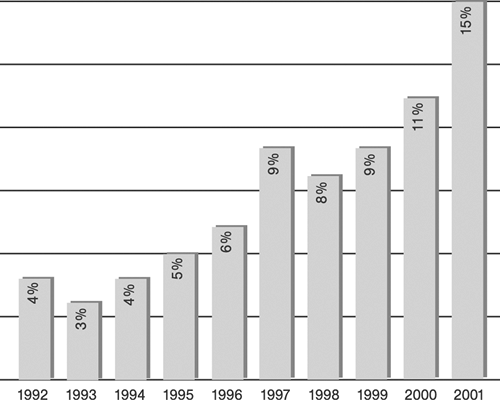 FIGURE 8-6. Percutaneous transluminal coronary angioplasty (PTCA) for acute myocardial infarction from 1992 to 2001 in Europe (percent of total). (Modified from Togni M, Balmer F, Pfiffner D, et al. Percutaneous coronary interventions in Europe 1992-2001. Eur Heart J. 2004;25:1208-1213.) |
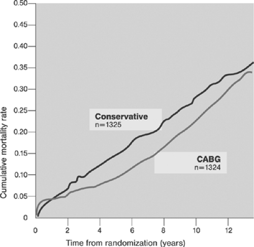 FIGURE 8-7. Cumulative mortality derived from trials comparing coronary artery bypass surgery (CABG), and medical therapy. (Modified from Yusuf S, Zucker D, Peduzzi P, et al. Effects of coronary artery bypass graft surgery on survival: overview of 10-year results from randomized trials by the Coronary Artery Bypass Graft Surgery Trialists Collaboration. Lancet. 1994;344:563-570.) |
Be currently certified in cardiovascular disease by the ABIM
Have satisfactorily completed the requisite training
Demonstrated clinical competence in the care of patients
Met the licensure requirements
Passed the secure exam for that discipline
Follow the training and practice pathways prescribed
To receive credit for performance of a therapeutic interventional cardiac procedure in the training pathway, a fellow must meet the following criteria:
Participate in procedural planning including indications for the procedure and the selection of appropriate procedure or instruments.
Perform critical technical manipulations of the case. (Regardless of how many manipulations are performed in any one “case,” each case may count as only one procedure.)
Be substantially involved in postprocedural management of the case.
Be supervised by the faculty member responsible for the procedure. (Only one fellow can receive credit for each case even if others were present.)
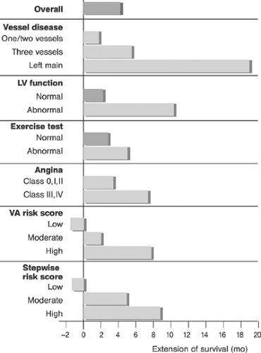 FIGURE 8-8. Survival after 10 years of follow-up after coronary artery bypass graft surgery in various subgroups of patients, from a meta-analysis of seven randomized studies. LV, left ventricular; VA, Veterans Administration. Angina class according the Canadian Cardiology Society Classification. (Modified from Yusuf S, Zucker D, Peduzzi P, et al. Effects of coronary artery bypass graft surgery on survival: overview of 10-year results from randomized trials by the Coronary Artery Bypass Graft Surgery Trialists Collaboration. Lancet. 1994;344:563-570.) |
To attest clinical competence, “The Board requires documentation that candidates for certification are competent in (1) patient care (which includes medical interviewing, physical examination, and procedural skills), (2) medical knowledge, (3) practice-based learning and improvement, (4) interpersonal and communication skills, (5) professionalism, and (6) systems-based practice.”
Recognizing the critical importance of competence and qualification, the majority of U.S. hospitals now grant privileges to interventional cardiologists on an individual basis following a detailed and extensive review and documentation of clinical skills and track record in addition to ABIM certification.
In Europe there are diverse national curricula for the interventional cardiology subspecialty, and European guidelines for interventional training have been formulated but not yet inaugurated. The European curriculum foresees 2 years of structured formal training in institutions performing a minimum of 800 procedures annually with the availability of at least two supervisors who have performed at least 1000 percutaneous coronary interventions (PCIs) and/or have a minimum of 5 years of experience dedicated to interventional cardiology. Advanced optional training includes formal training in peripheral interventional techniques.77 Some of these concepts have been proposed in earlier communications.78
TABLE 8-3. Comparison of Trials: Percutaneous Transluminal Coronary Angioplasty (PTCA) versus Coronary Artery Bypass Graft (CABG) | |||||||||||||||||||||||||||||||||||||||||||||||||||||||||||||||||||||||||||||||||||||||||||||||||||||||||||||||||||||||||
|---|---|---|---|---|---|---|---|---|---|---|---|---|---|---|---|---|---|---|---|---|---|---|---|---|---|---|---|---|---|---|---|---|---|---|---|---|---|---|---|---|---|---|---|---|---|---|---|---|---|---|---|---|---|---|---|---|---|---|---|---|---|---|---|---|---|---|---|---|---|---|---|---|---|---|---|---|---|---|---|---|---|---|---|---|---|---|---|---|---|---|---|---|---|---|---|---|---|---|---|---|---|---|---|---|---|---|---|---|---|---|---|---|---|---|---|---|---|---|---|---|---|
| |||||||||||||||||||||||||||||||||||||||||||||||||||||||||||||||||||||||||||||||||||||||||||||||||||||||||||||||||||||||||
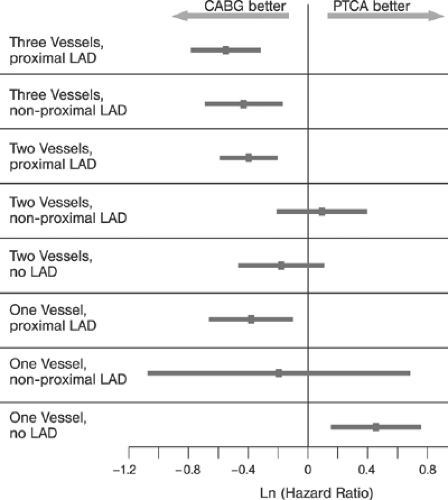 FIGURE 8-9. Adjusted hazard ratio (ln) with 95% confidence interval, for mortality, between percutaneous transluminal coronary angioplasty (PTCA) and coronary artery bypass graft surgery (CABG). (Modified from Eagle KA, Guyton RA, Davidoff R, et al. ACC/AHA 2004 guideline update for coronary artery bypass graft surgery. Circulation. 2004;110:e340-e437.) |
Quality
The principles of quality management based on international standards (International Organization for Standardization, ISO), have been introduced and are now well established in most interventional cardiology programs. These quality assurance guidelines regulate, standardize, and monitor all major areas of interventional activity. Important examples of national and international quality assurance guidelines that have broad international recognition and impact include:
Cardiac catheterization laboratory equipment and personnel80
Radiation protection in catheterization laboratory81
Terminology and documentation84
PCI documentation forms85
Institutional participation in standardized registries such as ACC-NCD84 allows consistent benchmarking and process control. Increasing awareness of the importance of adherence to evolving standards along with peer and market pressures continually reinforce the importance of stringent quality management, particularly in interventional therapy.
At least two conditions must be satisfied to allow external and internal comparisons of data between institutions, namely the precise definition of all the assessed outcome variables and consistent and honest reporting. Some of the variables frequently used in interventional cardiology to measure outcome are reviewed next.
Outcome
Unequivocally defined targets are required to enable a reliable assessment of the results of coronary interventions. Target variables include success, failure, and complications.
Definition of Success
Success of the procedure can be defined by angiographic, procedural, and clinical criteria applicable to a specific time or time period following the intervention.
Angiographic success, that is, the removal of a coronary obstruction, has been defined by several criteria. In the prestent era, angiographic success was mostly defined as reduction of stenosis diameter to <50%, the %DS (binary definition).85 Later a minimum luminal diameter (MLD), a continuous variable, was employed to better characterize the gradual nature of the degree of severity of residual stenoses (for review, see reference 86). Today zero degree residual stenosis is considered the optimal result of stent-supported angioplasty, and a residual stenosis <30% is considered an acceptable “stentlike” result of balloon angioplasty (for review, see reference 87). Angiographic calculation of the cross-sectional luminal area, although probably a
more accurate indicator than linear measurements, has not been widely applied in clinical practice.88 Normal antegrade coronary artery flow in the target vessel (thrombolysis in myocardial infarction, TIMI, III) should also be present. Angiographic success is determined following the intervention. In patients undergoing plain angioplasty, the immediate gain representing the maximum luminal expansion following dilatation is usually slightly reduced because of recoil (“early loss”) when measurement has been deferred.
TABLE 8-4. Comparison of Trials: Stent–percutaneous Transluminal Coronary Angioplasty (PTCA) versus Coronary Artery Bypass Graft (CABG) | ||||||||||||||||||||||||||||||||||||||||||||||||||||||||||||||||||||||||||||||||||||||||
|---|---|---|---|---|---|---|---|---|---|---|---|---|---|---|---|---|---|---|---|---|---|---|---|---|---|---|---|---|---|---|---|---|---|---|---|---|---|---|---|---|---|---|---|---|---|---|---|---|---|---|---|---|---|---|---|---|---|---|---|---|---|---|---|---|---|---|---|---|---|---|---|---|---|---|---|---|---|---|---|---|---|---|---|---|---|---|---|---|
| ||||||||||||||||||||||||||||||||||||||||||||||||||||||||||||||||||||||||||||||||||||||||
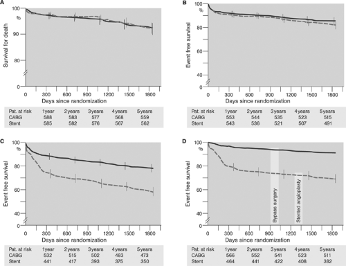 FIGURE 8-10. Comparison between coronary artery bypass grafting (CABG) and percutaneous coronary intervention (PCI) using bare-metal stents at 5-year follow-up; results from the Arterial Revascularization Therapies Study (ARTS) randomized trial. A: Kaplan-Meier curves showing freedom from death. B: Kaplan-Meier curves showing freedom from death, cerebrovascular accident, or myocardial infarction or revascularization. C: Kaplan-Meier curves showing freedom from death, cerebrovascular accident, or myocardial infarction or revascularization. D: Kaplan-Meier curves showing freedom from revascularization. (Adapted from Serruys PW, Ong ATL, van Herwerden LA, et al. Five-year outcomes after coronary stenting versus bypass surgery for the treatment of multivessel disease. The final analysis of the Arterial Revascularization Therapies Study (ARTS) randomized trial. J Am Coll Cardiol. 2005;46:575-581.) |
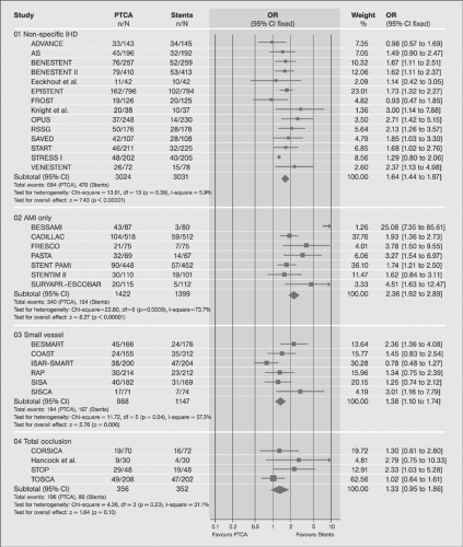 FIGURE 8-11. Six-month event rate in trials comparing percutaneous transluminal coronary angioplasty with and without stent. (Modified from Hill R, Bagust A, Bakhai A, et al. Coronary artery stents: a rapid systematic review and economic evaluation. Health Technol Assessment. 2004;35. Available at: www.ncchta.org/execsumm/summ835.htm. Accessed September 20, 2005.) |
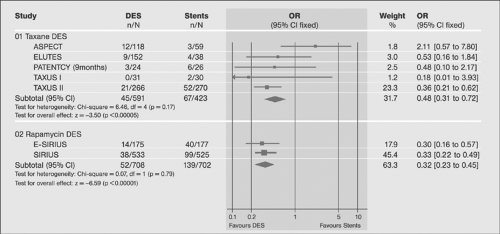 FIGURE 8-12. Results of trials comparing drug-eluting stents (DES) and bare-metal stents (BMS) in terms of 6-month adverse event rates (n, number of events, N, number of cases). (Modified from Hill R, Bagust A, Bakhai A, et al. Coronary artery stents: a rapid systematic review and economic evaluation. Health Technol Assessment. 2004;35. Available at: www.ncchta.org/execsumm/summ835.htm. Accessed September 20, 2005.) |
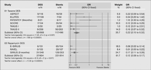 FIGURE 8-13. Results of trials comparing drug-eluting stents (DES) and bare-metal stents (BMS) in terms of binary (>50%) restenosis rate at 6 months (n – number of events, N – number of cases). (Modified from Hill R, Bagust A, Bakhai A, et al. Coronary artery stents: a rapid systematic review and economic evaluation. Health Technol Assessment. 2004;35. Available at: www.ncchta.org/execsumm/summ835.htm. Accessed September 20, 2005.) |
On follow-up (typically 6 months), restenosis and in-stent restenosis of the target lesion and coronary flow of the target vessel are described using the same parameters stated earlier (%DS, MLD, and TIMI). Restenosis usually refers to a reoccurrence of any stenosis >50% DS. This >50% or <50% status has been termed binary restenosis, and its frequency in a defined population of lesions and/or patients has accordingly been termed the binary restenosis rate (BRR). Alternatively, the actual degree of loss immediately after dilatation (“early loss”) and on follow-up (“late loss”) is indicated in percent or in absolute numbers (usually millimeters) at a specific point in time during follow-up. Currently, MLD measured at the narrowest point of the target lesion is the most frequently used parameter in clinical settings.
At present, angiographic definitions of success do not include any intermediate results or associated coronary damage such as side-branch closure, extensive stenting for an initially short lesion, or compromise of a nontarget vessel. It appears likely that additional angiographic criteria of success are required to enable us to discriminate results better in order for us to achieve better prognostication and to better assess new and emerging technologies. Examples of large differences in outcomes of interventions hidden within the current definition of angiographic success are provided in Figures 8-14 and 15.
Procedural success denotes angiographic success in absence of any clinically relevant complications. Procedural complications are most frequently summarized in quality assurance and clinical research protocols as major adverse cardiac (and cerebral) events (MAC[C]E) and include cardiac and noncardiac death, nonfatal myocardial (and cerebral) infarction, and target vessel revascularization (TVR) at predefined times during follow-up (up to 24 hours after the intervention, during the hospital stay, within 30 days, 6 months, and others). Complications concerning the access site include bleeding and vascular injuries. The former are standardized based on TIMI trial definitions for major (overt clinical bleeding with a drop in hemoglobin >5g/dL or in hematocrit >15%), minor (drop in hemoglobin >3g/dL and ≤5g/dL or hematocrit >9% and ≤15%), and none (bleeding event that does not meet the major or minor criteria).83 The last include iatrogenic dissections, fistulas, and pseudoaneurysms.
Peri-interventional myocardial injury (PMI) denotes any postprocedural rise in cardiac enzymes (cardiac troponins with peak values at 24 to 48 hours, CKMB with peak values at 24 hours) above the upper limit of normal (ULN89). Typical sampling intervals are at baseline, 6 to 9 hours, 12 to 24 hours, and as needed after the intervention. Cardiac troponins I and T are the preferred cardiac marker proteins because of their high sensitivity and specificity. The MB (muscle-brain) fraction of creatine kinase (CK) is preferred in patients with elevated cardiac markers at baseline because the serum kinetics are more favorable (Fig. 8.16).90 The incidence, prognostic significance, causes, prevention, and treatment of PMI have recently been reviewed.91
Clinical success denotes procedural success associated with relief of symptoms and freedom from adverse events over time. Restenosis and bypass attrition are the major limiting factors affecting long-term clinical success in coronary interventions and coronary surgery, respectively.
Definition of Procedural Failure and Complications
Procedural failure is present when the target lesion was not successfully revascularized for technical reasons such as an inability to cross or to dilate the lesion (target vessel failure, TVF). Nontechnical causes of failed revascularization such as a suspension of intervention because of systemic adverse effects such as contrast agent allergy are not considered TVF. Procedural failure may be accompanied by complications as outlined in the previous section. Definitions of some of the frequent procedural complications contained in the current ACC/AHA guidelines are summarized in Table 8-5.81 The patient-, lesion- and procedure-related factors of PMI have been reviewed and discussed elsewhere.91
Definition of the Quality of Interventions
The technical quality of interventions is hardly documented by the current quality assurance protocols. Surrogate indicators of quality include an elevated periprocedural serum concentration of cardiac markers of injury, procedural and fluoroscopy time, radiation exposure, and the use of contrast agents. Tables 8-6 and 8-7 provide examples of such surrogate measures. Documentation of more specific indicators of the technical quality of coronary interventions, such as suboptimal stent apposition, stent damage, underdilatation, incomplete lesion coverage, side-branch closure, or an impaired microcirculation, would probably improve analyses of outcomes and data interpretations. Extensive efforts to document results are, however, unrealistic in current clinical practice, and a broad implementation of expert interventional techniques might be a preferable course of action.
Percutaneous Coronary Interventions: Components
Percutaneous coronary intervention (PCI) is a complex process of an initialization followed by a number of iterative cycles, each consisting of image acquisition, intervention, and reassessment and concluded by a termination. The dynamics of each intervention depend on operator’s decisions to proceed or to terminate the procedure based on a continuous series of instant benefit and risk assessments. The ultimate criterion of a successful outcome is the sum of benefits to the patient. The outcome of the intervention is affected by factors related to the lesion, the patient, and the operator. Since these factors are incompletely defined and difficult to measure, direct measures of PCI process quality are not available. Surrogate criteria such as cost effectiveness must be interpreted with care and within the context of individual interventions.
An ideal PCI consists of an initialization, a single iterative cycle, and a termination. Ideal “real-world” PCI consists of an initialization, a minimum number of cycles converging in an optimum revascularization of the target lesion, and a termination.
In contrast to operator-independent mathematical automated iterative processes, PCI is highly operator dependent and its outcome is affected by a large number of frequently initially “hidden” variables. In simple terms, the PCI operator sets the stage by calling certain findings on coronary angiography an indication for catheter-based treatment and by defining the strategy of the intervention. Following the initialization, which ends with the last angiogram taken before guidewire placement, the main cycle of the intervention begins. During the main cycle the operator performs an interventional action, monitors the result, and, based on his interpretation, terminates the procedure or proceeds with the next cycle of the intervention. The operator’s decisions are based on his estimates of expected benefits and potential risks of his actions. The ability to avoid and to predict impending risks and to resolve materialized risky situations are hallmarks of experienced operators. In addition, secondary factors including incurred procedural costs, potential legal implications, patients’ wishes, psychological disposition of the operator, and other variables also affect the decision process. Besides avoiding unnecessary risks and staying in control in difficult situations, the master operator also typically uses a minimum number of required iterative cycles to achieve technically and clinically excellent results, while keeping the complication rates and material costs low compared to less accomplished operators. These attributes produce the impression of seeming simplicity, straightforwardness, and elegance. The strategic considerations concerning PCI have been outlined in chapter 4. In the subsequent section, general considerations and patient- and lesion-related factors concerning PCI are discussed.
In contrast to operator-independent mathematical automated iterative processes, PCI is highly operator dependent and its outcome is affected by a large number of frequently initially “hidden” variables. In simple terms, the PCI operator sets the stage by calling certain findings on coronary angiography an indication for catheter-based treatment and by defining the strategy of the intervention. Following the initialization, which ends with the last angiogram taken before guidewire placement, the main cycle of the intervention begins. During the main cycle the operator performs an interventional action, monitors the result, and, based on his interpretation, terminates the procedure or proceeds with the next cycle of the intervention. The operator’s decisions are based on his estimates of expected benefits and potential risks of his actions. The ability to avoid and to predict impending risks and to resolve materialized risky situations are hallmarks of experienced operators. In addition, secondary factors including incurred procedural costs, potential legal implications, patients’ wishes, psychological disposition of the operator, and other variables also affect the decision process. Besides avoiding unnecessary risks and staying in control in difficult situations, the master operator also typically uses a minimum number of required iterative cycles to achieve technically and clinically excellent results, while keeping the complication rates and material costs low compared to less accomplished operators. These attributes produce the impression of seeming simplicity, straightforwardness, and elegance. The strategic considerations concerning PCI have been outlined in chapter 4. In the subsequent section, general considerations and patient- and lesion-related factors concerning PCI are discussed.
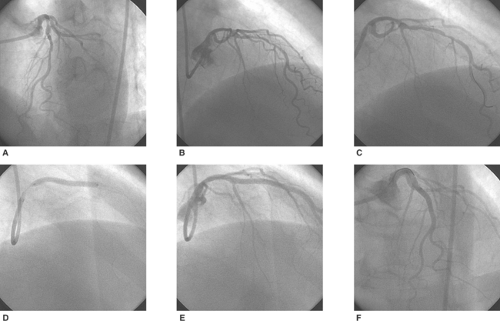 FIGURE 8-14. Long, proximal left anterior descending (LAD) artery stenosis, drug-eluting stenting (DES). 66-year-old male with Canadian Cardiology Society (CCS) III° angina on exertion and anterior wall ischemia documented by stress echocardiography. Angiogram revealed high proximal long LAD up to 90% stenosis (A,B). Following guidewire placement (C) 3.5/3 mm Taxus (Boston Scientific, Natick, MA, USA) was deployed at 14 bar and after dilated to improve the strut apposition and to optimize the proximal transition between native vessel wall and stent (D). Final angiograms revealed complete LAD revascularization (E,F). |
General Considerations
Initial steps in setting the stage for performing PCI include stating the indication, obtaining informed consent, and examining the patient.
Indications
PCI is principally considered in patients with documented coronary artery lesions causing myocardial ischemia or adversely affecting the prognosis of the patient. PCI is indicated when based on evidence it appears more beneficial to the patient compared to other forms of treatment. The indications change in time as a consequence of progress in understanding the pathophysiology of CAD and as a result of evolving technologies. Although the appropriateness of PCI is usually not contested in patients with acute coronary syndromes, PCI indications in patients with chronic coronary syndromes appear less straightforward. Although the guidelines provide a useful framework for PCI indications (Tables 8-8, 8-9 and 8-10),67,81,82 they by no means replace the decision process needed to address the specific needs of individual patients. Frequently, to decide
on the most appropriate treatment for individual patients, a thorough discussion of findings followed by consensus decisions between interventionist and surgeon involving the patient is required.
on the most appropriate treatment for individual patients, a thorough discussion of findings followed by consensus decisions between interventionist and surgeon involving the patient is required.
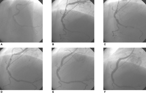 FIGURE 8-15. Full metal jacket coronary artery reconstruction: 51-year-old man with inferior wall ST elevation myocardial infarction (STEMI). Angiogram showed single-vessel coronary disease, AHA segment 3 right coronary artery (RCA) “culprit” lesion in a moderately tortuous, diffusely diseased infarct-related RCA (A). Following guidewire placement, diffuse atherosclerosis with multiple plaques, spasms, and proximal (AHA segment 1) dissection were seen (B). Dilatation of the “culprit” lesion was performed using a 3.0/20-mm balloon and resulted in RCA closure (C). Following stent placement (3.0/18 mm Lekton motion, Biotronik at 10 bar) antegrade coronary blood flow was restored (D). Subsequently, because of multiple proximal segment plaques and plaque shifts occurring after each subsequent stent implantation, four successive distal to proximal overlapping stent placements were required (3.5/8 mm, 4.0/13 mm 2÷, 4.0/20 mm, all Lekton motion, Biotronik at 14 bar) (E). Final angiogram documented “full metal jacket” RCA AHA segment 1 and 2 revascularization and spot “culprit” lesion revascularization (F). |
Informed Consent
Performance of PCI is contingent on consent of the patient. Thus, in all cases an informed consent must be signed by the patient well ahead of the intended intervention; typically, in elective cases 24 hours is considered adequate. In severely compromised or unconscious patients, as is often the case in emergency procedures, informed consent may be difficult to obtain. In these cases it is customary to assume that the physician acts in the best interest of his patient; a brief written statement describing the circumstances leading to the decision to perform PCI is usually considered sufficient. However, because any interventions without patient’s explicit prior consent are open to different legal interpretations, the operator should clearly understand the customary legal practices in his environment.
An interview with the patient and a core physical examination including chest auscultation, auscultation and palpation of peripheral pulses, and the Allen test for radial procedures must be conducted before an informed consent is obtained. Usually a printed standard consent form is used and modified as necessary for individual patients. The main purpose of the interview is to convey full information to the patient regarding the expected benefits and risks of the planned treatment. The interview should be conducted unhurriedly in a quiet environment. All the information should be communicated honestly, clearly, and understandably. The explanation of expectations and risks must be complete and realistic. Although risk statistics are available in the literature (Tables 8-11 and 8-12,81,92 it is preferable to use the actual data from the operator’s institution (Table 8-13). Other individual risks should be explicitly stated. In patients undergoing multiple interventions during a single hospital stay, separate informed consent is needed for each intervention. In high-risk procedures it is advisable to conduct the interview in the presence of a third person cosigning the document. Signed and dated consent becomes a part of the patient’s medical chart confirming to the legal requirements.
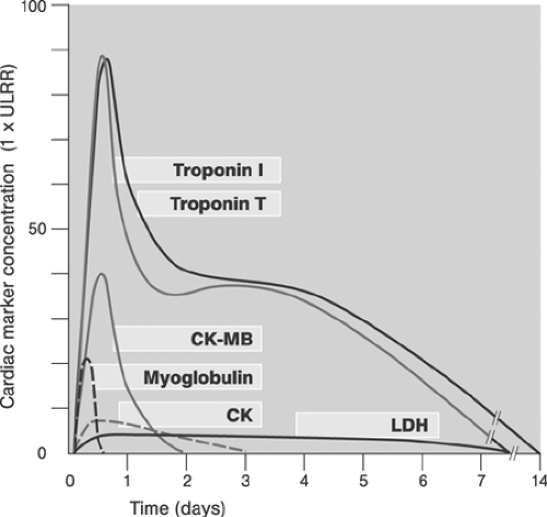 FIGURE 8-16. Kinetic profiles of cardiac marker proteins associated with ST elevation myocardial infarction. (Modified from French JK, White HD. Clinical implications of the new definition of myocardial infarction. Heart. 2004;90:99-106.) |
Peri-PCI Orders and Evaluations
Before PCI, standard evaluations performed in all patients, include resting 12-lead ECG and laboratory examinations (potassium, creatinine, prothrombin time, platelets count, TSH, glucose (<24 hours before PCI), and chest x-ray (optional).
Suggested written pre-PCI orders are stated as follows:
Shave and prep both groins or prepare other access site as specified
Keep NPO (nothing by mouth) after midnight except for clear liquids; for patients scheduled for the second half of the day, a light breakfast is allowed; avoid dehydration!
Maintain medication except long-acting diuretics and biguanides (metformin; see later discussion)
Establish the intravenous line prior to transport to the catheterization laboratory
Have patient void on call and put on hospital gown
Administer sedatives, such as diazepam 5 mg PO, if necessary
Following an uncomplicated PCI, the patient is transferred for up to 24-hours monitoring. Post-PCI orders typically include:
Timing of sheath removal (if patient remains asymptomatic)
Method of hemostasis
Duration of compression required in hours (if no closure device was used)
Protocol to check puncture site for bleeding
Protocol to check blood pressure and peripheral pulse, e.g., q15min ÷2, q30min ÷4, q60min ÷3h
Requirements for ECG monitoring (in hours)
Fluid intake requirements, orally and/or intravenously; if inadequate, loop diuretic requirements
Timing of intake of patient’s usual medication
Patients with complex or complicated procedures are transferred to a fully monitored bed, usually an intensive care unit. Post-PCI orders state the planned management. Unstable patients do not leave catheterization laboratory until stable.
Risk Assessment; Patient-Related Factors
Comprehensive evaluation of all risk factors is critical to estimate the risk of the intervention. The overall latent risk of PCI (see chapter 4) comprises primarily patient- and lesion-related risk factors. Knowledge of patient-related risk factors prior to the intervention allows risk reduction by targeting their prevention, their stabilization, and in some cases even their elimination. Principal patient-related risk factors are reviewed.
Low-Risk Patients
Low-risk patients are considered those with no record of any of the established patient- and/or lesion-related risk factors such as exemplified by a healthy young man with single-vessel CAD and type A target lesion in a side branch. However, even in low-risk patients the complications are not zero, and it is precisely in this group where any major complication seems to weigh double. The best prevention of avoidable unexpected complications is by adopting the same thorough fully concentrated approach to the intervention as if a technically demanding case were being treated.
Patients with Poor Left Ventricular Function
Left ventricular function (LVF) is usually assessed by quantitative echocardiography or angiography. Global systolic LV dysfunction may be graded as light (left ventricular ejection fraction, LVEF >45%), moderate (LVEF ∼ 30% to 45%), or severe (LVEF <30%). The segmental systolic LVF is also assessed93 and related to distribution of coronary artery lesions. Diastolic LVF is not routinely evaluated prior to PCI.
The latent PCI risk increases with decreasing systolic LVF. Segmental LVF is important to differentiate between healthy and dysfunctional myocardium and myocardial scar. In some cases, the viability of the myocardium may be assessed. Matching the segmental LVF with coronary lesions allows better risk assessment and prognostication, and it is useful in decisions on PCI targets. The jeopardy score94 shown in Table 8-14 provides a means to assess the risk from PCI based on the severity of CAD and segmental LVF.
Patients with moderate to severe systolic LV dysfunction require optimal management of heart failure including adequate hydration and stable medication (ACE inhibitors, beta-blockers, diuretics, antialdosterone agents) prior to elective PCI. Patients with persistent heart failure despite optimal medical management with LVEF <20% to 30% and a jeopardy score >3 are candidates for prophylactic mechanical support during PCI. Patients who should receive mechanical support routinely as soon as possible prior to PCI are those with marked hemodynamic compromise in the settings of an acute coronary syndrome or with cardiogenic shock defined by systolic blood pressure <90 mm Hg or a value 30 mm Hg below basal levels for at least 30 minutes, an elevated arteriovenous oxygen difference (>5.5 mL/dL), and a depressed cardiac index
(<2.2 L/min/m2 body-surface area) in the presence of elevated pulmonary-capillary wedge pressure (>15 mm Hg).95 Indications for mechanical support other than severe reversible systolic LV dysfunction include:
(<2.2 L/min/m2 body-surface area) in the presence of elevated pulmonary-capillary wedge pressure (>15 mm Hg).95 Indications for mechanical support other than severe reversible systolic LV dysfunction include:
TABLE 8-5. Definitions of Procedural Complications | ||||||||||||||||||||||||
|---|---|---|---|---|---|---|---|---|---|---|---|---|---|---|---|---|---|---|---|---|---|---|---|---|
| ||||||||||||||||||||||||
TABLE 8-6. Selected Surrogate Indicators of Quality of Interventions (Heart Centre Coswig, 2004) | ||||||||||||||||||||
|---|---|---|---|---|---|---|---|---|---|---|---|---|---|---|---|---|---|---|---|---|
| ||||||||||||||||||||
TABLE 8-7. Mean Fluoroscopy and Cine Times of Coronary Interventions and Diagnostics (Mean ± SD) (Heart Centre Coswig, 2004) | ||||||||||||
|---|---|---|---|---|---|---|---|---|---|---|---|---|
|
Multivessel coronary artery disease and ongoing ischemia scheduled for delayed revascularization
Multivessel coronary artery disease and ongoing ischemia not amenable to revascularization (selected cases)
TABLE 8-8. Indications for Percutaneous Coronary Intervention (PCI), European Society of Cardiology Recommendations
Indication
Class of Recommendation
Level of Evidence
CHRONIC CORONARY SYNDROMES
Objective large myocardial ischemia (in presence of any lesion subsets, except chronic total occlusions which cannot be crossed)
I
A
Chronic total occlusion
IIa
C
High surgical risk
IIa
B
Multivessel disease
IIb
C
Unprotected left main in the absence of other revascularization options
IIb
C
Routine stenting of de novo stenosis; native artery, venous grafts
I
A
ACUTE CORONARY SYNDROMES
NSTEMI and instable angina pectoris (early PCI, high risk group)
I
A
STEMI (primary PCI; unselected patients)
I
A
STEMI (primary PCI, contra–indication to fibrinolysis)
I
A
STEMI (primary PCI, presentation 3–12 h after onset of symptoms)
I
A
STEMI (primary PCI, routine stenting)
I
A
STEMI (facilitated PCI following fibrinolysis)
No recommendation
–
STEMI (facilitated PCI following GP IIb/IIIa inhibitors)
No recommendation
–
STEMI (rescue PCI after failed fibrinolysis)
I
B
STEMI (primary PCI, cardiogenic shock)
I
C
STEMI (routine angiography after successful fibrinolysis)
I
A
STEMI (PCI for ischemia following successful fibrinolyis)
I
B
NSTEMI, non–ST elevation myocardial infarction; STEMI, ST elevation myocardial infarction. Modified from Silber S, Albertsson P, Aviles FF, et al. Guidelines for percutaneous coronary interven–tions. The Task Force for Percutaneous Coronary Interventions of the European Society of Cardiology. 2005;26:804–847.
High-risk PCI such as that of unprotected left main or complex multivessel lesions in patients with moderate to severe LV dysfunction
In patients considered for mechanically supported PCI, significant aortic and peripheral artery occlusive disease must be excluded before device implantation. The intra-aortic balloon pump (IABP)96 is the mechanical support device most frequently used in the catheterization laboratory (for review, see reference 97). Although percutaneous implantation from the contralateral femoral artery site is usually straightforward, several limitations should be kept in mind:
Limited intravascular residence time (<3 maximally 7 to 10 days)
Reduced efficacy in patients with arrhythmias
Limited efficacy in the presence of mild aortic insufficiency
Need for residual authentic LV function
Requirements for therapeutic anticoagulation
Presence of any of the exclusion criteria
In patients with severe intractable LV dysfunction and/or cardiogenic shock due to reversible causes such as acute
myocardial ischemia, cardiopulmonary support (CPS) and extracorporeal membrane oxygenation (ECMO) assist devices provide excellent short-term support.98 Depending on the size of the CPS cannula and volume status, a patient’s circulation can be maintained for a short period of time (<3 days) regardless of cardiac rhythm and residual output. However, in contrast to IABP, CPS does not unload LV and does not improve coronary perfusion. Supported PCI is a technically demanding
procedure demanding complete revascularization in one stage and the lowest possible complication rates, and should therefore be performed only by experienced operators. In patients with protracted or irreversible LV dysfunction, weaning from the mechanical support device might be difficult and in some cases even impossible. Other mechanical LV support devices, such as the left atrial-femoral artery bypass and surgically implanted left ventricular assist devices, have not been primarily designed for mechanical support in the catheterization laboratory and do not play a significant role in PCI99
TABLE 8-9. ACC/AHA Recommendations for Percutaneous Coronary Interventions Based on Clinical Symptoms: Asymptomatic/CCS Class I Angina patients | ||||||||||||||||||
|---|---|---|---|---|---|---|---|---|---|---|---|---|---|---|---|---|---|---|
| ||||||||||||||||||
TABLE 8-10. ACC/AHA Recommendations for Percutaneous Coronary Intervention (PCI) Based on Clinical Symptoms: CCS Class II–IV Angina Patients with Single–or Multivessel Coronary Disease on Medical Therapy | ||||||||||||||||||
|---|---|---|---|---|---|---|---|---|---|---|---|---|---|---|---|---|---|---|
| ||||||||||||||||||
TABLE 8-11. In–hospital Rates of Major Complications | ||||||||||||||||||||||||||||||||||||||||||||||||||||||||||||||||||||||||||||||||||||||||||||
|---|---|---|---|---|---|---|---|---|---|---|---|---|---|---|---|---|---|---|---|---|---|---|---|---|---|---|---|---|---|---|---|---|---|---|---|---|---|---|---|---|---|---|---|---|---|---|---|---|---|---|---|---|---|---|---|---|---|---|---|---|---|---|---|---|---|---|---|---|---|---|---|---|---|---|---|---|---|---|---|---|---|---|---|---|---|---|---|---|---|---|---|---|
| ||||||||||||||||||||||||||||||||||||||||||||||||||||||||||||||||||||||||||||||||||||||||||||
TABLE 8-12. In–hospital Rates of Major Complications Related to Underlined Coronary Artery Disease and Procedure | ||||||||||||||||||||||||||||||||||||||||||||||||||||||||||||||||||||||||||||||||||||||||||||||||||||||||
|---|---|---|---|---|---|---|---|---|---|---|---|---|---|---|---|---|---|---|---|---|---|---|---|---|---|---|---|---|---|---|---|---|---|---|---|---|---|---|---|---|---|---|---|---|---|---|---|---|---|---|---|---|---|---|---|---|---|---|---|---|---|---|---|---|---|---|---|---|---|---|---|---|---|---|---|---|---|---|---|---|---|---|---|---|---|---|---|---|---|---|---|---|---|---|---|---|---|---|---|---|---|---|---|---|
| ||||||||||||||||||||||||||||||||||||||||||||||||||||||||||||||||||||||||||||||||||||||||||||||||||||||||
TABLE 8-13. In–hospital Rates of Major Complications of Percutaneous Coronary Intervention (PCI) | ||||||||||||||||
|---|---|---|---|---|---|---|---|---|---|---|---|---|---|---|---|---|
| ||||||||||||||||
TABLE 8-14. Calculation of Baseline Left–ventricular (LV) Dysfunction in Patients with Coronary Artery Disease–Jeopardy Score | ||||||||||||||||||||||||||||||||
|---|---|---|---|---|---|---|---|---|---|---|---|---|---|---|---|---|---|---|---|---|---|---|---|---|---|---|---|---|---|---|---|---|
| ||||||||||||||||||||||||||||||||
Diabetic Patients
Type II diabetes is a critical risk factor for vascular multimorbidity100 and a strong independent predictor for cardiovascular events.101 In context with PCI, high rate of left main lesions, multivessel and diffuse CAD, large plaque burden, and poor collateralization are of particular relevance.102,103,104 Correspondingly, the complication rates, long-term mortality, and restenosis rates of diabetics undergoing PCI are greater compared with nondiabetics.105,106 Clinical outcomes of PCI using balloon dilatation alone107,108 and BMS with GPIIb/IIIa inhibitors were worse compared to patients treated with surgery.109,110,111 Although DESs have been shown to be superior to BMSs in diabetic patients as well,112 their efficacy compared to bypass surgery still remains unclear; important trials such as FREEDOM and BARI 2D may clarify the questions of the most appropriate treatment for diabetics with multivessel (MVD) CAD and are underway. Based on the available evidence, surgery is the better option for elective treatment of diabetics with MVD, particularly when internal mammary artery (IMA) grafts to the LAD can be used.113 In patients with single nonproximal LAD vessel disease, percutaneous treatment using DES and GPIIb/IIIa receptor inhibitors should be considered, whereas in those with single proximal LAD disease, either one of the two revascularization strategies may be considered.114 Patients with acute coronary syndromes, particularly those with ST elevation myocardial infarction (STEMI), are treated by PCI.115
Adverse morphology of diabetic CAD associated with multiple associated functional abnormalities116,117 and worse PCI outcomes of diabetics versus nondiabetics in all subgroups113,114 mandate a number of specific considerations in planning PCI in diabetics versus nondiabetics:
Greater likelihood of underestimation of the severity and extent of the coronary disease
Greater likelihood of vascular and organ multimorbidity
Metabolic instability
Greater likelihood of contrast agent-induced nephropathy
Greater potential of side effects from medications, especially biguanides
Greater likelihood of immune incompetence and healing defects
Optimal management of diabetics undergoing PCI requires optimal management of all identified risk factors, meticulous PCI technique, and thorough aftercare. The risk of contrast-induced nephropathy (CIN), particularly in patients with preexisting renal insufficiency, mandates a close surveillance of renal function during the peri-interventional period (Table 8-15)118 and adequate hydration. To avoid metabolic complications, tight metabolic control and adjustments in medication are also important. Table 8-16 provides a check list for diabetics undergoing PCI.
Patients with Renal Disease
The presence of pre-existing renal disease is a marker of poor outcome in patients undergoing PCI119,120 and CABG.121,122 Although patients with renal insufficiency have benefited from the introduction of coronary stenting123 and off-pump coronary surgery,124 the negative prognostic implications of renal disease persist.125 For patients with end-stage renal disease in the prestent era, CABG was favored over angioplasty122; however, no conclusive data comparing PCI and CABG utilizing recent revascularization strategies are available. Therefore, at present both strategies of coronary revascularization should
be considered, yet the least aggressive technique allowing complete revascularization should be selected. Guidelines applicable to coronary revascularization of patients on chronic hemodialysis are provided by the National Kidney Foundation.126
be considered, yet the least aggressive technique allowing complete revascularization should be selected. Guidelines applicable to coronary revascularization of patients on chronic hemodialysis are provided by the National Kidney Foundation.126
TABLE 8-15. Stages of Renal Insufficiency in Patients with Type II Diabetes | ||||||||||||||||||||||||||||||
|---|---|---|---|---|---|---|---|---|---|---|---|---|---|---|---|---|---|---|---|---|---|---|---|---|---|---|---|---|---|---|
| ||||||||||||||||||||||||||||||
In clinical practice the detection of renal disease and exact definition of the degree of renal dysfunction prior to PCI are of key importance in avoiding the risk of contrast-induced nephropathy (CIN), defined as ≥25% increase in serum creatinine from baseline or absolute increase by 44.2 μmol/L (0.5 mg/dL) within 48 hours after application of a contrast agent lasting for a minimum of 2 days.127,128 Patients at risk for developing CIN include:
Patients with pre-existing renal disease
Patients with type II diabetes regardless of age
Elderly, aged, and dehydrated patients
Patients on nephrotoxic medication
Patients following prolonged hypotension
Patient following high contrast media exposure (>200 mL), repeated contrast media exposures, or the application of high-osmolarity agents
Measures to prevent CIN are summarized in Table 8-17.
Admission and procedural rules for high-risk CIN patients undergoing PCI include:
Hospitalization 2 days prior to PCI
Adequate hydration and judicious use of diuretics!
Staging diagnostic coronary angiography and PCI by >10 days
Avoiding other procedures requiring contrast agents
Using biplane angiography, if available
Consideration of preventive hemodialysis in high-risk patients with high contrast exposure129
In patients developing CIN despite preventive measures, the severity of renal dysfunction can be determined using the glomerular filtration rate (GFR) or using measurements of creatinine clearance calculated with the Cockcroft and Gault equation130: Creatinine clearance (mL/min) = (140 – age in years) ÷ (body weight in kg)/72 ÷ creatinine concentration in serum (mg/100 mL). When creatinine serum concentrations are measured in SI units (μmol/L), it is necessary to multiply the results by 0.82 in males and 0.85 in females.131 Table 8-18 is a summary of stages of chronic renal insufficiency based on GFR measurements.
Management of patients with established CIN includes:
Transfer to intensive care unit where acute hemodialysis is available
Close monitoring of input and output
Daily determination of creatinine, urea, electrolytes for 5 days as needed
Consultations with nephrologists as needed
Table 8-19 summarizes recommended measures for treating CIN.
Patients with Thyroid Disease
Application of iodinated contrast agents during PCI is associated with massive iodine exposure. However, although ∼15 to 100 g of iodine, corresponding to 1500 to 10,000 times the total iodine content of the human body, is applied, only a fraction of this amount, approximately 0.1 to 0.001%(0.5 to 36 μg/mL) is biologically active free inorganic iodine. In addition, some free iodine is generated by deiodination of the organically bound iodine (∼0.1 to 0.2% of the total administered dose within 1 hour of exposure).134 The free iodine may, however, induce thyrotoxicosis in susceptible patients such as those with hyperthyroid disease, immunologically based thyroid disease, or autonomic thyroid tissue, and multinodular goiter in individuals living in endemic iodide-deficient regions and in patients receiving certain medications (e.g., amiodarone, expectorants) and having particular nutritional habits (e.g., kelp ingestion).
Iodide-induced thyrotoxicosis (IIT) may be associated with sustained adverse cardiovascular effects including atrial and ventricular arrhythmias, conduction abnormalities, and heart failure. Life-threatening symptoms of persistent heart failure and dysrhythmias may occur in compromised patients.135,136
To reduce the risk of IIT, systematic screening is required prior to PCI. A standard checklist includes:
Assessment of the history of thyroid disease
Exclusion of offensive medication
Palpation of the thyroid gland
Laboratory examinations (thyroid-stimulating hormone [TSH] assay is performed; if below normal, free tri-iodothyronine [T3] and, less frequently, free tetraiodothyronine [fT4] are measured).
Preventive measures prior to PCI are recommended in patients at risk for IIT. Extended drug treatment is mandatory in patients at risk and in those with thyrotoxicosis and vital indications for PCI (Table 8-20). In stable patients with overt hyperthyroidosis, PCI is deferred until the thyroid function has been normalized.
TABLE 8-16. Check list and Recommendations for Percutaneous Coronary Intervention (PCI) Admission of Patients with Type II Diabetes | |||||||||||||||||||||||||||||||||||||||||||||||||||||||||||||||||||||||||||||||||||
|---|---|---|---|---|---|---|---|---|---|---|---|---|---|---|---|---|---|---|---|---|---|---|---|---|---|---|---|---|---|---|---|---|---|---|---|---|---|---|---|---|---|---|---|---|---|---|---|---|---|---|---|---|---|---|---|---|---|---|---|---|---|---|---|---|---|---|---|---|---|---|---|---|---|---|---|---|---|---|---|---|---|---|---|
|
Patients with Allergy
Adverse responses to iodine contrast agents (ICA) occur in ∼5% to 10% of patients, although they are very mild in the majority of cases. Moderate to severe adverse responses have been estimated at 1% to 2% and fatalities at ∼0.001% (0.0003% to 0.0026%) of ICA applications. Use of nonionic low-osmolality contrast agents is associated with less patient discomfort and may be safer.137 The differences between contrast agents have been rarely statistically meaningful in the conducted trials because of the low frequency of target events.138
Allergylike and true allergy responses are more common in patients with a history of:
Asthma
Food allergies to iodine containing seafood and shellfish (e.g., scallops and shrimp)
Metal allergies such as nickel, cobalt, manganese
Allergies to medications
In predisposed patients, the symptoms are not only more frequent but also frequently more severe.
TABLE 8-17. Prevention of Contrast-induced Nephropathy (CIN) | |||||||||||||||||||||||
|---|---|---|---|---|---|---|---|---|---|---|---|---|---|---|---|---|---|---|---|---|---|---|---|
|
Although the exact mechanism of adverse responses to ICA has not been established, usually nonanaphylactoid (chemotoxic, vasovagal, and idiopathic) and anaphylactoid (idiosyncratic “allergylike” and true allergic) responses are distinguished. Nonanaphylactoid chemotoxic responses may be dose dependent and include primarily nephrotoxic and neurotoxic as well as some cardiovascular effects (e.g., arrhythmogenicity). Anaphylactoid responses may be nonspecific reactions due to as yet unknown mediators or they may be mediated by antibodies (IgE) or T lymphocytes. Nearly all severe responses occur within minutes (≤20 minutes) following ICA exposure. In some cases late responses (up to 7 and more days), consisting usually of mild urticaria, bronchospasm, or renal dysfunction, may occur.
Based on the symptoms, several grades of severity may be distinguished. The majority of responses are very mild, consisting of urticaria, pruritus, and diaphoresis without systemic symptoms (grade 1). Grade 2 is associated with mild to moderate dyspnea due to laryngeal edema and bronchospasm, hypotension due to vasodilatation, and abdominal symptoms (nausea, vomiting, abdominal pain). In grade 3 moderate to severe dyspnea and profound hypotension occur. Grade 4 refers to severe cardiocirculatory and pulmonary compromise and/or arrest.
TABLE 8-18. Stages of Chronic Renal Insufficiency (CRI) | |||||||||||||||||||||
|---|---|---|---|---|---|---|---|---|---|---|---|---|---|---|---|---|---|---|---|---|---|
| |||||||||||||||||||||
TABLE 8-19. Suggested Management of Patients with Contrast-Induced Nephropathy (CIN) | ||||||||||||||||||||||||||||||||||||||
|---|---|---|---|---|---|---|---|---|---|---|---|---|---|---|---|---|---|---|---|---|---|---|---|---|---|---|---|---|---|---|---|---|---|---|---|---|---|---|
| ||||||||||||||||||||||||||||||||||||||
Prophylactic medication is recommended for all predisposed patients and for those with previous adverse responses to ICA. The suggested oral regimen among accepted protocols consists of:
Prednisone 50 mg PO12, 6, and 1 hour prior to exposure
Diphenhydramine, H1-antihistamine, 50 mg PO 12 and 1 hour prior to exposure
Ranitidine, H2-histamine receptor blocker, 50 mg PO 1 hour prior to exposure.
TABLE 8-20. Prevention of Iodine-induced Hyperthyroidism in Patients Undergoing Percutaneous Coronary Interventions | ||||||||||||
|---|---|---|---|---|---|---|---|---|---|---|---|---|
|
An intravenous regimen can alternatively be given in patients unable to take oral medication.
Immediate treatment is necessary when symptoms suggestive of adverse responses to ICA occur during PCI. In patients with moderate to severe symptoms, immediate supplementary oxygen, intravenous administration of fluids, and intramuscular administration of adrenalin (0.5 mL of 1:1000 solution) are required. Because of the potential, albeit small, risk of cardiopulmonary arrest, the PCI operator must be thoroughly familiar with manifestations and management of anaphylactic shock and full-scale resuscitation (for review, see references 139,140,141). Table 8-21 provides a summary of the recommended adverse reaction ICA management.
In patients with pronounced vasovagal responses during PCI, typical treatment consists of:
Fluid intravenous (IV) supplementation using crystalline solution (e.g., Ringer lactate) or plasma expander (e.g., starch derivatives such as HAES 6%)
Atropine 0.5 to 1.0 mg IV
Catecholamines (dopamine, dobutamine) IV, if needed.
PCI should not be resumed before stable blood pressure (systolic BP ≥100 mm Hg) and heart rate have been restored in a fully asymptomatic patient.
TABLE 8-21. Recommended Prevention and Treatments for Adverse Responses to Iodinated Contrast Agents | |||||||||||||||||||||||||||||||||||||||||||||||
|---|---|---|---|---|---|---|---|---|---|---|---|---|---|---|---|---|---|---|---|---|---|---|---|---|---|---|---|---|---|---|---|---|---|---|---|---|---|---|---|---|---|---|---|---|---|---|---|
| |||||||||||||||||||||||||||||||||||||||||||||||
Elderly and Aged Patients
At present the majority of patients undergoing PCI are 60 to 75 years old with the proportion of patients >75 years of age (including those older than 85) growing. Advancing age has been associated with worse outcome following plain balloon angioplasty142,143 and stent-supported angioplasty.144,145 In fact, the outcome progressively worsens with an increase in age indicated as a continuous and discrete variable.146 Typical examples of the effects of advancing age on outcome following coronary intervention are shown in Tables 8-22 and 23 and Figure 8-17.
Although not necessarily a risk factor by itself, age serves as a pathophysiological marker for a more advanced coronary artery disease (greater complexity of CAD, greater proportion of multivessel disease) and increasing incidence of comorbidities as shown in Table 8-24.147
Although the current ACC/AHA PCI guidelines abstained from special recommendations regarding PCI in the elderly81 (except for recommendations regarding primary PCI in cardiogenic shock), it is obvious that elderly and aged patients considered for coronary interventions constitute a special group requiring special considerations and strategic planning, including those concerning complete versus palliative revascularization, procedural staging, and early mobilization to reduce procedural risk.
TABLE 8-22. Outcomes of Percutaneous Coronary Intervention at 30 Day and 1 Year Stratified by Age | ||||||||||||||||||||||||||||||||||||||||||||||||||||||||||||||||||||||||||||||||||||||||||||||||||||||||||||||||||||||||||||||||||||||||||||||||||||||||||||
|---|---|---|---|---|---|---|---|---|---|---|---|---|---|---|---|---|---|---|---|---|---|---|---|---|---|---|---|---|---|---|---|---|---|---|---|---|---|---|---|---|---|---|---|---|---|---|---|---|---|---|---|---|---|---|---|---|---|---|---|---|---|---|---|---|---|---|---|---|---|---|---|---|---|---|---|---|---|---|---|---|---|---|---|---|---|---|---|---|---|---|---|---|---|---|---|---|---|---|---|---|---|---|---|---|---|---|---|---|---|---|---|---|---|---|---|---|---|---|---|---|---|---|---|---|---|---|---|---|---|---|---|---|---|---|---|---|---|---|---|---|---|---|---|---|---|---|---|---|---|---|---|---|---|---|---|---|
| ||||||||||||||||||||||||||||||||||||||||||||||||||||||||||||||||||||||||||||||||||||||||||||||||||||||||||||||||||||||||||||||||||||||||||||||||||||||||||||
TABLE 8-23. Outcomes of Percutaneous Coronary Intervention at 1 Year Stratified by Age | ||||||||||||||||||||||||||||
|---|---|---|---|---|---|---|---|---|---|---|---|---|---|---|---|---|---|---|---|---|---|---|---|---|---|---|---|---|
| ||||||||||||||||||||||||||||
Panvascular Patients
Patients with clinically significant disease in at least two major vascular territories (panvascular patients) are mostly diabetics at any age and the elderly (>65 and <75 years) individuals carrying a higher risk of interventions.100,148 Knowledge of the panvascular status based on a more extensive pre-PCI vascular workup is important for implementing risk reduction strategies. In addition, comprehensive panendovascular or hybrid strategies of global revascularizations might reduce the overall procedural risk and should be considered in all relevant cases.149
Severely Ill Patients
Severely and terminally ill patients (assumed life expectancy ≤6 months) include patients with a chronic terminal disease complicated by CAD and patients with life-threatening CAD
associated with major neurological deficits, and/or multiorgan failure without prior terminal disease.
associated with major neurological deficits, and/or multiorgan failure without prior terminal disease.
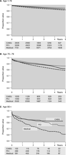 FIGURE 8-17. Kaplan-Meier curves of patient survival over time for three age groups A-C as outlined, following percutaneous coronary intervention. (Adapted from Graham MM, Ghali WA, Faris PD, et al. Survival after coronary revascularization in the elderly. Circulation. 2002;105:2378.) |
Patients with terminal disease complicated by CAD are usually not considered candidates for surgical revascularization, and definitive or palliative PCI represents an option in principle in most cases. In patients with life-threatening CAD, percutaneous treatment is offered in most cases as a primary mode of treatment. In contrast to conventional emergency PCI, in this cohort of severely ill patients not only the target lesions but all critical coronary lesions should be revascularized in one stage. To avoid futile treatments, however, an interdisciplinary consensus and the patient’s declared will are required. Decision making should consider:
Degree of severity and expected reversibility of the hemodynamic and electrical compromise
Severity, complexity, and technical accessibility of the CAD
Severity and expected reversibility of the LV dysfunction
Status of the terminal disease
Presence and expected reversibility of major neurological deficits
Presence and severity of other comorbid conditions
Critical risk and benefit assessment
In patients with terminal disease presenting with a critical CAD, all medical and relevant social aspects of the disease and intended treatment should be broached and discussed.
Risk Assessment; Target Lesion-Related Factors
Assessment of diagnostic coronary angiograms in patients considered for PCI includes determining the status of the target interventional site (target lesion, target vessel, target ostium) and that of nontarget vessels (see Chapter 3B for details). In addition, LVF, the ascending aorta and aortic arch, and the vascular path from the access to the target ostium are evaluated. Based on these factors the strategy of the intervention and instrumentation is selected. Selection of the strategy depends on a clear understanding of the risks and benefits. Selection of the instrumentation depends on the understanding of the performance characteristics of the endovascular instrumentation to meet the anatomical requirements. Lack of direct visual inspection of the interventional site in interventional techniques (as opposed to surgery) explains some of the intricacies facing the interventionist. Thus, for an optimal PCI correct reading and interpretation of the angiograms are the most critical issues in design and execution of the individual interventions. Whereas during the planning stage the operator makes theoretical assumptions based on his previous experience, during the intervention he must integrate visualization (imaging equipment), vision (eye), interpretation (brain), and tactile feedback of manipulation (hand) into a real-time and frequently instantaneous action. To become eventually an informed intuition common to master operators, each step of this process must be understood, studied, and trained.
The prognostic relevance of target lesion and target vessel morphology for the outcome of coronary interventions was pointed out by the 1988 American College of Cardiology/American Heart Association (ACC/AHA) angiographic classification of coronary artery lesions into A-C types.150 At that time the expected success rates were >85% for type A lesions, 60% to 85% for moderately complex type B lesions, and <60% for complex type C lesions. Successful angioplasty was defined as a ≥20% increase in luminal diameter with the final diameter stenosis <50% in the absence of major complications including death, acute myocardial infarction, or the need for emergency bypass.150 The clinical relevance of the ACC/AHA lesion classification has been proven by several
investigators.151,152,153 Ellis et al. proposed further subclassification of type B lesions into B1 (i.e., lesions with one B criterion) and B2 (i.e., lesions with >1 B criterion).151 In the same study, high-grade, bend, and bifurcation stenoses, chronic total occlusions, and male gender were highlighted as negative prognostic factors. An analogous subclassification of type C lesions was introduced by Myler et al.152 In this study, the presence of a thrombus, increasing lesion length, diffuse disease, calcification, and angulated, high-grade (>95%) and bifurcation lesions were identified as negative prognostic factors.
investigators.151,152,153 Ellis et al. proposed further subclassification of type B lesions into B1 (i.e., lesions with one B criterion) and B2 (i.e., lesions with >1 B criterion).151 In the same study, high-grade, bend, and bifurcation stenoses, chronic total occlusions, and male gender were highlighted as negative prognostic factors. An analogous subclassification of type C lesions was introduced by Myler et al.152 In this study, the presence of a thrombus, increasing lesion length, diffuse disease, calcification, and angulated, high-grade (>95%) and bifurcation lesions were identified as negative prognostic factors.
TABLE 8-24. Increase in Multimorbidity with Age | ||||||||||||||||||||||||||||||||||||||||||||||||||||||||||||||||||||||||
|---|---|---|---|---|---|---|---|---|---|---|---|---|---|---|---|---|---|---|---|---|---|---|---|---|---|---|---|---|---|---|---|---|---|---|---|---|---|---|---|---|---|---|---|---|---|---|---|---|---|---|---|---|---|---|---|---|---|---|---|---|---|---|---|---|---|---|---|---|---|---|---|---|
| ||||||||||||||||||||||||||||||||||||||||||||||||||||||||||||||||||||||||
In an attempt to improve the prognostic significance of angiographic coronary lesions, the Society of Coronary Angiography and Interventions (SCAI) introduced a group I-IV classification.154 However, with the broad availability of stents, evolving instrumentation, and better technical skills, the prognostic implications of lesion morphology has begun to change, reducing the overall need for complex classifications. Thus, although different lesions are still associated with different prognoses with regard to technical success and long-term outcome, the use of stents and antiplatelet medication has clearly attenuated the prognostic significance of their morphology. At present the majority of coronary lesions (>90%) can be revascularized with results comparable to those of type A lesions on the ACC/AHA classification. The remaining ∼10% of lesions are technically more difficult to treat and have a higher risk of complications. Whereas in the former group the operator’s experience and mastery may not be as critical, in the latter group they are the most critical determinant of outcome. At present, as in 1980s, the lowest technical success rates are achieved in revascularizations of chronic total occlusions (CTOs); defined as occlusions older than 3 months.
Uncomplicated Lesions
ACC/AHA type A150 or SCAI type I lesions154 are considered uncomplicated, and technical and procedural success is >90%. The majority of direct stenting PCI is performed on this subset of lesions. However, the availability of stents and particularly of DES has considerably expanded the scope of angiographic lesions which now may be considered prognostically equivalent to uncomplicated lesions. Figure 8-14 provides an example of a formal type C (lesion >20 mm) ACC/AHA classification lesion now considered amenable to direct stenting. Thus, lesions without a thrombus, heavy calcification, and/or highly complex morphology may be considered prognostically equivalent to uncomplicated lesions. It should be kept in mind that an uncomplicated lesion can become complicated if the proximal access is difficult. Moreover, angiographic visualization might not tell the whole story: “surprise” complexity of a presumably uncomplicated lesion (and vice versa!) might become evident only in the course of the intervention. It is the dynamics of changes of lesions undergoing interventions that ultimately decides on their dignity. Careful attention to the findings of the intermediary angiograms throughout the intervention is important to recognize a lesion initially classified as benign that is turning critical during the course of the intervention.
Thrombotic Lesions
Thrombotic lesions have been considered high-risk type B or type C on the ACC/AHA classification.150,152,155 Although the advent of stents and antiplatelet agents has mitigated some of the adversities associated with the mechanically and biologically unstable thrombotic lesions,156,157 their treatment still carries a higher risk of complications. In fact, full prognostic
significance of thrombotic lesions as the source of proximal (target site) and distal (microcirculatory) complications has only recently been fully recognized (for review, see reference 158). Thrombus formation accompanies unstable lesions; in patients with acute coronary syndromes it is almost obligatory. However, compared to coronary angioscopy, the ability of coronary angiography to detect a thrombus is limited (Figs. 8-18, 8-19, 8-20).159 Using angioscopy as a point of reference, angiography detects only ∼20% of thrombi.160,161 Although the presence of thrombi is associated with increased interventional risk of, for example, reocclusion, reinfarction, and death, the actual degree of risk may vary considerably.155,156,157 In addition to primary thrombi detected on the initial angiograms, secondary thrombus formation may occasionally be visualized in the course of an intervention in patients with multiple critical lesions, poor coronary flow, poor LVF, procoagulatory syndromes, or inadequate anticoagulation, and patients undergoing long and complex procedures.
significance of thrombotic lesions as the source of proximal (target site) and distal (microcirculatory) complications has only recently been fully recognized (for review, see reference 158). Thrombus formation accompanies unstable lesions; in patients with acute coronary syndromes it is almost obligatory. However, compared to coronary angioscopy, the ability of coronary angiography to detect a thrombus is limited (Figs. 8-18, 8-19, 8-20).159 Using angioscopy as a point of reference, angiography detects only ∼20% of thrombi.160,161 Although the presence of thrombi is associated with increased interventional risk of, for example, reocclusion, reinfarction, and death, the actual degree of risk may vary considerably.155,156,157 In addition to primary thrombi detected on the initial angiograms, secondary thrombus formation may occasionally be visualized in the course of an intervention in patients with multiple critical lesions, poor coronary flow, poor LVF, procoagulatory syndromes, or inadequate anticoagulation, and patients undergoing long and complex procedures.
Acute totally occlusive coronary thrombi are depicted as occluded vessels lacking collaterals, and subtotally occlusive thrombi are shown as intraluminal fixed or floating filling defects in stenotic segments. In emergency interventions in patients with multiple coronary artery occlusions it is critical for the operator to identify the “culprit” acute occlusion. Attempts to revascularize chronic total occlusions while leaving the infarct lesion untouched may be fatal in high-risk patients. In the absence of collateral vessels the distinction between acute closure and CTO might be difficult. Careful review of angiograms before beginning the intervention is critical. In difficult crossing, another careful review of angiograms may give the operator cues to revise PCI strategy.
Particularly in high-risk patients and in patients presenting with a protracted prehospital course, multiple thrombi may be found. Some thrombi may be sharply demarcated while others are displayed as intraluminal haziness. In some cases even large thrombi are angiographically visible only by indirect signs such as “no flow” or “slow flow.” The distinction between a thrombus and an embolus on angiography is unreliable. The absence of angiographic evidence for atherosclerosis (smooth endothelial interfaces) and the presence of arrhythmias or intracardiac masses suggest embolus.
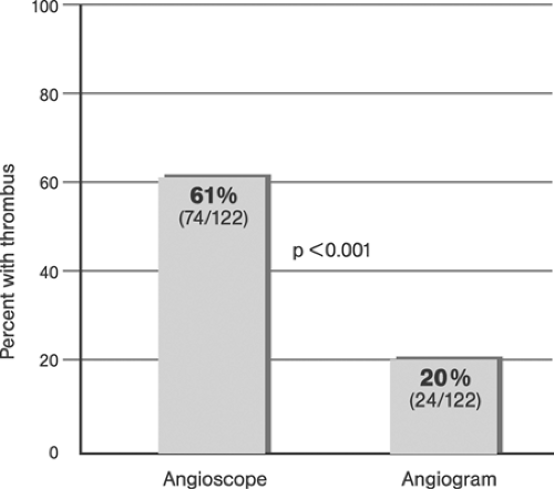 FIGURE 8-18. Incidence of angiographic versus angioscopic thrombi. (Modified from White CJ, Ramee SR, Collins TJ, et al. Coronary thrombi increase PTCA risk: angioscopy as a clinical tool. Circulation. 1996;93:253-258.) |
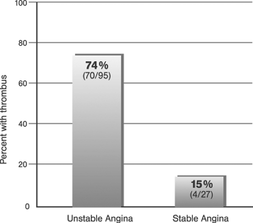 FIGURE 8-19. Incidence of angioscopic thrombi in patients with unstable and stable angina pectoris. (Modified from White CJ, Ramee SR, Collins TJ, et al. Coronary thrombi increase PTCA risk: angioscopy as a clinical tool. Circulation. 1996;93:253-258.) |
The principle treatment options include mechanical extraction, dilatation/stenting with the administration of GIIb/IIIa platelet aggregation inhibitors, fibrinolysis, or any combination of these with or without thromboembolic protection devices.
Mechanical extraction shows promise in proximal fresh totally occlusive thrombi, provided it can be performed by an experienced operator. Before deploying the thrombectomy device, the feasibility and the risks of mechanical injury and downstream embolization should be assessed. In most devices, ≥7F systems are required, and a concomitant administration of GIIb/IIIa platelet inhibitors is obligatory in the absence of contraindications. In patients with distal thrombi, diffuse disease, difficult proximal segment, or high plaque burden, mechanical thrombectomy
cannot be recommended. Figure 8-21 provides an example of failed mechanical thrombectomy in a distal location.
cannot be recommended. Figure 8-21 provides an example of failed mechanical thrombectomy in a distal location.
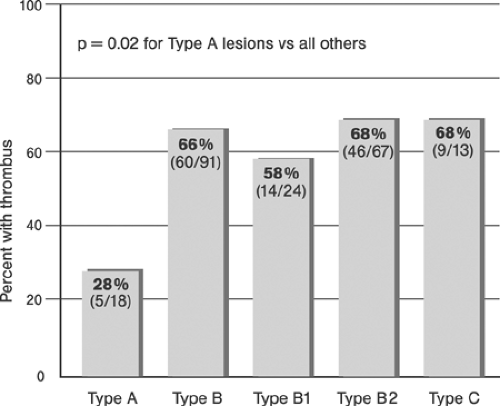 FIGURE 8-20. Incidence of angioscopic thrombi among ACC/AHA lesion categories. (Modified from White CJ, Ramee SR, Collins TJ, et al. Coronary thrombi increase PTCA risk: angioscopy as a clinical tool. Circulation. 1996;93:253-258.) |
The majority of thrombotic lesions are presently treated by administering GP IIb/IIIa platelet receptor inhibitors early and using a guidewire and balloon to recanalize occlusions and stenting the culprit lesion. Distal protection devices (DPDs) should be considered in all interventions involving saphenous vein grafts (SVGs) (exception: diffusely degenerated SVG), in large thrombus masses, and whenever possible in “the last remaining” vessel, in cases with reduced LVF or a large amount of jeopardized rest myocardium. To successfully deploy the DPD the target vessel should be large (≥3.5 mm diameter) and allow for deployment distal to the target lesion.
Fibrinolytic agents are rarely used to treat thrombotic lesions in the catheterization laboratory because of their low efficacy compared to PCI. Possible exceptions are patients with highly diffuse coronary artery disease and multiple thrombotic lesions, and patients in whom PCI access to the target lesion failed. In the absence of contraindications, superselective or locoregional intracoronary fibrinolysis should be considered in these patients. In these cases one of the second- or third-generation selective thrombolytic agents should be administered via OTW catheters. The efficacy of fibrinolytic agents as a measure of last resort in resilient cases associated with distal embolizations, subtotal distal occlusions, and slow antegrade coronary artery flow is, however, doubtful. In contrast, in all cases, the definite risk of bleeding complications must be taken into account.
The formation of secondary de novo thrombi during PCI prompts an immediate review of angiograms to exclude mechanical causes (intimal flaps, dissections, deformed struts). In addition, activated clotting time (ACT) is assessed. Mechanical causes of thrombus formation must be addressed and eliminated immediately. ACT <250 seconds is corrected by an additional dose of unfractionated heparin (up to 5000 U UFH). In addition, in the absence of contraindications, GP IIb/IIIa platelet receptor inhibitors are administered, preferably using the intracoronary route. Fibrinolytic agents are usually not indicated. In rare cases, persistent thrombosis associated with clinical instability may require prompt consultation with a cardiac surgeon to review surgical options.
Calcified Lesions
Vascular calcifications are hydroxyapatite crystal deposits within the intima and, less frequently, the media162 resulting from passive physicochemical and active cellular processes.163
Coronary artery lesions are frequently calcified, yet the low sensitivity of angiography often leaves them undetected. Thus, compared to IVUS, coronary angiography detects only 25% of one-quadrant calcium, 50% of two-quadrant calcium, 60% of three-quadrant calcium, and 85% of four-quadrant calcium lesions (Table 8-25 and Fig. 8.22). In addition, better angiographic visibility of superficial and extensively circumferential calcifications has been described (Figs. 8-23, 8-24).164
Because the mass attenuation coefficient of calcium is greater than that of soft tissues,165 calcium deposits are seen as dark and usually irregularly shaped spots or “railroad tracks” in the course of the coronary artery on native films. They are typically located in the proximal to middle coronary segments. With increasing energy (kilo-electron volts, keV) of x-ray radiation, the difference between the mass attenuation coefficients for calcium and soft tissues decreases, making detection of calcifications more difficult, as seen for example in obese patients.
Calcified lesions may be “bad” or “good” news.166,167: they may destabilize the lesion by increasing the heterogeneity of stress distribution across the arterial wall (primarily probable in plaques with superficial calcification), but they may also increase the mechanical stability via a “natural stenting” effect (most likely in deeper calcifications). In addition, the prevention of positive remodeling might actually contribute to plaque stabilization (see chapter 1 for review).
Heavily calcified lesions are rigid and therefore more difficult to dilate; dilatations require higher inflation pressures associated with lower technical success168 and a higher risk of complications,169 particularly of dissections.170
In patients with proximal high-grade extensively calcified lesions, IVUS should be considered to assess the feasibility and risk of the intervention. Yet, the accessibility of these lesions to IVUS probes is frequently limited, leaving the operator no other option but to rely on angiography. To reduce risk, heavily calcified high-grade proximal LAD lesions that are difficult to assess should be operated in most cases. In patients with less heavily calcified lesions, standard DES-supported angioplasty can usually be performed safely. Stents with greater radial force may be required to counteract the low mechanical instability of dilated calcified lesions. Primary debulking using rotational atherectomy may be considered in some cases.171,172
Low-grade (<50%) proximal calcified lesions may complicate access to more distal high-grade (calcified or noncalcified) target lesions. “Unplanned” interventions on these proximal sites should be avoided by selecting the lowest profile instrumentation available, a gentle and meticulous technique associated with, and the least possible number of passages. Optimal selection of the guidewire is important to conduct PCI atraumatically. Medium stiffness of the tip, high shape retention, and high slipperiness are preferable in most cases. Increasing complexity of the target lesions increases the need for improved crossing ability, and thus for greater stiffness and better force transmission of the shaft. However, if shafts are too stiff they may stretch the artery by directing the advancing equipment into the walls. In doing so, the operator increases not only the friction (and force needed to overcome the resistance) but also the risk of dissection. In these cases, the potentials of different strategies, such as using two guidewires, should be explored. Once the guidewire has crossed the target lesion and has been securely placed, low-profile high-track balloon dilatation catheters and low-profile firm crimp stent delivery systems are critical to success. Direct stenting of calcified lesions requires a prior assessment of the dilatability of the lesion. Undersized balloon predilatations appear preferable in most cases.
Patients with extensive diffuse calcifications are poor candidates for PCI and coronary surgery, and consensus decisions of interventionists and surgeons usually determine the optimal approach. In patients selected for PCI, the principal options are focal and palliative coronary repair, plaque modification using excimer laser angioplasty, and extensive stenting using DES.
High Plaque Burden Lesions
Arterial enlargement may let an advanced atherosclerosis remain “hidden” without luminal encroachment173 and keep it from being visualized by angiography. In addition, compared to
IVUS, the ability of angiography to detect the geometry and morphology of lesions appears limited. Specifically, cross-sectional geometry (Tables 8-26 and 8-27; Fig. 8.25),174 the longitudinal extent of atherosclerosis,175 and atherosclerotic remodeling (Fig. 8.26) are imperfectly visualized by angiography (for review, see reference 176). Thus, in interpreting coronary angiograms the operator must be keenly aware of the fact that the true intramural extent and severity of coronary atherosclerosis may be underestimated and the true lesion morphology may be distorted.
IVUS, the ability of angiography to detect the geometry and morphology of lesions appears limited. Specifically, cross-sectional geometry (Tables 8-26 and 8-27; Fig. 8.25),174 the longitudinal extent of atherosclerosis,175 and atherosclerotic remodeling (Fig. 8.26) are imperfectly visualized by angiography (for review, see reference 176). Thus, in interpreting coronary angiograms the operator must be keenly aware of the fact that the true intramural extent and severity of coronary atherosclerosis may be underestimated and the true lesion morphology may be distorted.
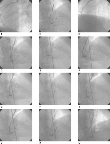 FIGURE 8-21. Failed thrombectomy percutaneous coronary intervention (PCI), right coronary artery (RCA). A 49-year-old man with an acute inferior ST elevation myocardial infarction (STEMI) involving the right ventricle, complete atrioventricular block requiring transvenous pacing, rhythm instability, and severe hemodynamic compromise requiring high catecholamine support and fibrinolysis prior to admission. Following intra-aortic balloon pump (IABP) placement, coronary angiography revealed two-vessel disease (RCA and left anterior descending artery, LAD) with marked right dominance. The infarct-related artery (IRA) RCA was a diffusely diseased vessel with a distal subtotal thrombotic occlusion (A-C). Guidewires were placed into the inferior interventricular and posterolateral ramus of the RCA (D). As outpatient thrombolytic treatment had failed, the decision was made to extract the thrombus using a thrombectomy device (Pronto, Vascular Solutions). Following device placement (E), the thrombus was removed, and the device retracted. Subsequent angiography revealed an extensive dissection distal to the crux, associated with a dissecting occlusion of the posterolateral ramus and subtotal occlusion of the inferior interventricular ramus (F). To allow stenting, a guidewire placed in the inferior interventricular ramus had to be removed, then two stents were placed in the posterolateral ramus (Lekton motion 3.0/25 mm and 3.5/25 mm at 10 bar, Biotronik) with “no-reflow” (G-I). Subsequently, the proximal dissection (J) was stented (3.5/25 mm Coroflex, Braun at 12 bar) (K) and TIMI II° into the posterolateral ramus, with persistent occlusion of the inferior interventricular ramus was achieved. Despite multiple redilatations and extensive pharmacotherapy including two additional intracoronary boluses of eptifibatide, “slow-flow” into the posterolateral ramus and “no-flow” of the inferior interventricular ramus persisted (L). Following consultation with cardiac surgeons the patient was referred for immediate coronary artery bypass surgery. |
TABLE 8-25. Relation of Angiographic versus Intravascular Ultrasound Definition of Coronary Lesions Calcification Patterns | |||||||||||||||||||||||||||||||||||||||||||||||||||||||||||||||||
|---|---|---|---|---|---|---|---|---|---|---|---|---|---|---|---|---|---|---|---|---|---|---|---|---|---|---|---|---|---|---|---|---|---|---|---|---|---|---|---|---|---|---|---|---|---|---|---|---|---|---|---|---|---|---|---|---|---|---|---|---|---|---|---|---|---|
| |||||||||||||||||||||||||||||||||||||||||||||||||||||||||||||||||
Atherosclerotic lesions with a large plaque burden are either focal or diffuse. The amenability of focal high-grade lesions to dilatation depends on their tissue composition and circumferential distribution. Dilatability decreases with increasing rigidity and circumferential extent, while the risk of complications, dissection, and rupture increases at the same time. Because of the limited ability of angiography to detect either of the two determinants of dilatability, complementary IVUS guidance is recommended in proximal focal high plaque burden lesions. When such lesions span the entire circumference, bypass revascularization should be considered. Alternatively, primary debulking using DCA, with or without IVUS guidance, may be reasonable.177,178,179
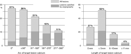 FIGURE 8-22. Topographic distribution of coronary artery calcifications. (Left panel) Frequency distribution of the maximum arc of intravascular ultrasound target lesion calcium. Coronary angiography detected 25% of one-quadrant calcium, 50% of two-quadrant calcium, 60% of three-quadrant calcium, and 85% of four-quadrant calcium. (Right panel) Frequency distribution of the lengths of intravascular ultrasound target lesion calcium. Coronary angiography detected 42% of calcium ≤5 mm in length, 63% of calcium 6 to 10 mm in length, and 61% of calcium >11 mm in length. (Modified from Mintz GS, Popma JJ, Pichard AD, et al. Patterns of calcification in coronary artery disease: a statistical analysis of intravascular ultrasound and coronary angiography in 1155 lesions. Circulation. 1995;91:1959-1965.) |
Coronary angiography may not detect lesions with a diffusely distributed large plaque burden (Fig. 8.27). In some cases diffuse discrete endoluminal irregularities, particularly when associated with distal stenoses or diffusely narrowed arteries supplying large territories, indicate a severe diffuse disease. In these patients flow-pressure wire measurements may be helpful in determining the optimal revascularization strategy. The hemodynamic relevance of both focal and diffuse disease can
be determined using the pullback technique. Vigorous medical management is indicated in patients with distally decreased fractional flow reserve (FFR) and gradual normalization on pullback, whereas conventional PCI appears justified in patients with a focal significant decrease documented by FFR. In patients with both a diffuse and a focal reduction in FFR, additional factors such as limiting symptoms, risk profile, and previous response to medical treatment are helpful to determine the most desirable approach to further management. In patients selected for PCI, focal atraumatic repair and maximum prevention are required.
be determined using the pullback technique. Vigorous medical management is indicated in patients with distally decreased fractional flow reserve (FFR) and gradual normalization on pullback, whereas conventional PCI appears justified in patients with a focal significant decrease documented by FFR. In patients with both a diffuse and a focal reduction in FFR, additional factors such as limiting symptoms, risk profile, and previous response to medical treatment are helpful to determine the most desirable approach to further management. In patients selected for PCI, focal atraumatic repair and maximum prevention are required.
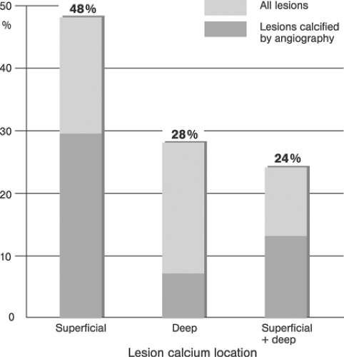 FIGURE 8-23. Distribution of lesion calcium locations according to depth. Coronary angiography detected superficial target lesion calcium, either alone (sensitivity, 60%) or in combination with deep calcium (sensitivity, 54%), more often than it detected isolated deep target lesion calcium (sensitivity, 24%, P <.0001). (Modified from Mintz GS, Popma JJ, Pichard AD, et al. Patterns of calcification in coronary artery disease: a statistical analysis of intravascular ultrasound and coronary angiography in 1155 lesions. Circulation. 1995;91:1959-1965.) |
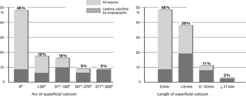 FIGURE 8-24. Topographic distribution of coronary artery calcifications. (Left) Frequency distribution of the arc of superficial target lesion calcium. Coronary angiography detected 34% of one-quadrant superficial calcium, 59% of two-quadrant superficial calcium, 69% of three-quadrant superficial calcium, and 86% of four-quadrant superficial calcium. (Right) Frequency distribution of the lengths of superficial target lesion calcium. Coronary angiography detected 50% of superficial calcium ≤5 mm in length, 67% of superficial calcium 6 to 10 mm in length, and 65% of superficial calcium >11 mm in length. Thus, the sensitivity of coronary angiography increased with an increasing arc or length of lesion-associated superficial calcium (both P <.0001). (Modified from Mintz GS, Popma JJ, Pichard AD, et al. Patterns of calcification in coronary artery disease: a statistical analysis of intravascular ultrasound and coronary angiography in 1155 lesions. Circulation. 1995;91:1959-1965.) |
Instrumentation
Angiographic findings determine the operator’s selection of instrumentation, and optimal instrumentation is critical to technical success, procedural time, material costs, and minimizing the risk of the procedure. In this section, selected instrumentation for coronary interventions is reviewed; a more extensive discussion is provided in chapter 5.
Puncture Needle, Introductory Guidewire, and Vascular Sheath
Puncture Needles
Purpose
Puncture needles are designed to allow smooth penetration of the skin and underlined tissue, atraumatic puncture of the vessel’s front wall, and stable positioning of the tip within the lumen.
Requirements
Ideally, puncture needles are sharp and relatively stiff, allowing smooth penetration and good steering even in highly fibrotic or calcified tissues. A large bore is required to allow optimal blood jet return, which is indicative of complete vessel wall penetration and unobstructed endoluminal seating.
Materials and Design
Puncture needles are metallic tubes with a sharp distal tip and proximal plastic hub for firm grip and contain a Luer-Lok connector. Most needles are manufactured from thin-walled, large-bore tubes of stainless steel. Two-piece (outer needle and stylet) and three-piece (outer needle, stylet, and obturator) needles are now rarely used in current interventional practice.
Occasionally, a soft two-piece Teflon catheter-over-needle is employed, permitting the safe use of hydrophilic guiding catheters.
Occasionally, a soft two-piece Teflon catheter-over-needle is employed, permitting the safe use of hydrophilic guiding catheters.
TABLE 8-26. Comparison of Lesions Measured by Intravascular Ultrasound (IVUS) and Quantitative Coronary Angiography According to Severity of IVUS Eccentricity of ≥3.0 and <3.0 | |||||||||||||||||||||||||||||||||||||||||||||
|---|---|---|---|---|---|---|---|---|---|---|---|---|---|---|---|---|---|---|---|---|---|---|---|---|---|---|---|---|---|---|---|---|---|---|---|---|---|---|---|---|---|---|---|---|---|
| |||||||||||||||||||||||||||||||||||||||||||||
TABLE 8-27. Comparisons of Angiographic Eccentric and Concentric Lesions with Quantitative Intravascular Ultrasound (IVUS) Parameters | ||||||||||||||||||||||||||||||||
|---|---|---|---|---|---|---|---|---|---|---|---|---|---|---|---|---|---|---|---|---|---|---|---|---|---|---|---|---|---|---|---|---|
| ||||||||||||||||||||||||||||||||
Standard puncture needles for femoral, brachial, and axillary artery access are 9 to 10 cm, and for the radial access approximately 5 cm long. The outer and inner diameters of the puncture needles are usually indicated in gauges (which originally—in 19th-century England—was an industrial measure for the diameter of wire). Gauge sizes (G) are indicated in fractions of an inch (1 in. = 2.54 cm) (Table 8-28).
Standard puncture needles and Teflon catheter-over-needle for access via the transfemoral, transbrachial, and transaxillar arteries are 18G (0.049 in. outer/0.042 in. inner diameter), and for transradial access 21G (0.032 in. outer/0.022 in. inner diameter) to allow smooth passage of 0.035-in. and 0.021-in. introductory guidewires, respectively.
Introductory Guidewires
Purpose
Following successful vascular puncture, an introductory J-curve guidewire is used for needle replacement to secure vascular access, a maneuver termed the Seldinger procedure after its inventor.180
Requirements
The most important requirements for introductory guidewires are atraumatic design, and the adequate length and support for the introduction of the sheath.
Material and Design
Introductory guidewires are typically 30 cm long with an 0.018-in. (radial) and a 0.021-in. or 0.035-in. (other sites) diameter. They are usually J-tipped and manufactured out of stainless steel or polymers.
Introductory Sheath
Purpose
Following stable endoluminal introductory guidewire placement, a sheath is used to establish stable percutaneous vessel access, which allows safe introduction and exchange of the catheter.
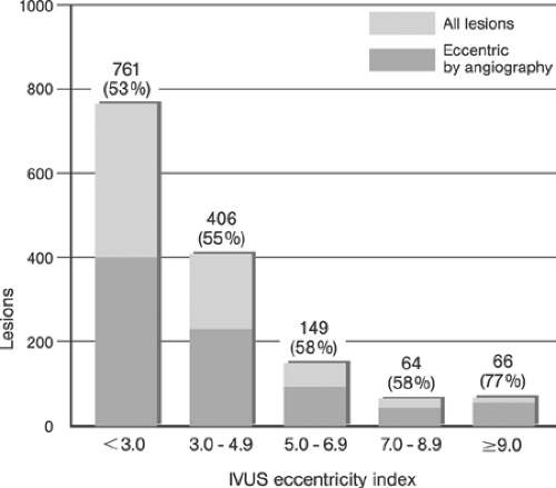 FIGURE 8-25. Frequency distribution of the intravascular ultrasound (IVUS) eccentricity index. The total number of lesions in each IVUS group is shown with the percentage of lesions with eccentricity by angiography shown in parentheses. (Modified from Mintz GS, Popma JJ, Pichard AD, et al. Limitations of angiography in the assessment of plaque distribution in coronary artery disease a systematic study of target lesion eccentricity in 1446 lesions. Circulation. 1996;93:924-931.) |
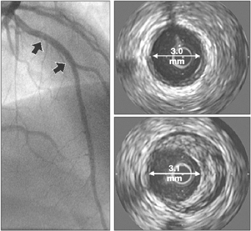 FIGURE 8-26. Example of coronary remodeling. (Left) Normal left anterior descending (LAD) artery on angiography displays mild concentric (upper right) and moderate eccentric (lower right) degree of atherosclerosis on IVUS, as shown at two selected sites. Positive remodeling at the more distal site (lower right) prevents detection of atherosclerosis by angiography. (Reproduced with permission from Nissen SE, Yock P. Intravascular ultrasound novel pathophysiological insights and current clinical applications. Circulation. 2001;103:604-616. ) |
Requirements
The vascular sheath should allow atraumatic passage through tissue, including the vessel wall. Requirements are high flexibility, high kink resistance, a soft atraumatic tip, and biological compatibility (including low thrombogenicity).
Material and Design
A vascular sheath typically consists of a shaft with a pneumatic seal, side arm, and inside dilator. A fixation or lock mechanism between the two parts is needed to prevent separation of the sheath and the dilator during advancement. A standard introductory sheath is 15 cm long. The version whose internal diameter ranges from 4F to 5F (French size F, named in commemoration of the 19th-century French manufacturer of surgical instruments Joseph-Frederic-Benoit Charriere; 1F corresponds to 0.33 mm) is used for diagnostic catheterization, and the 5F to 7F version typically for percutaneous interventions. Longer (30, 45, 65, 80, and 90 cm) and bigger (up to 26F) introductory sheaths are available to facilitate access to the target vessel through elongated or tortuous vascular paths or to permit the use of larger devices during endovascular interventions.
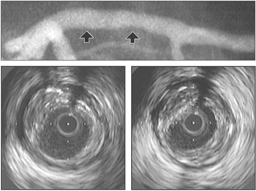 FIGURE 8-27. Angiographic underestimation of coronary artery atherosclerosis. Minor angiographic luminal irregularities (top) appeared on intravascular ultrasound (IVUS) as a diffuse atherosclerosis, shown at two sites (arrows). (Reproduced with permission from Nissen SE, Yock P. Intravascular ultrasound novel pathophysiological insights and current clinical applications. Circulation. 2001;103:604-616. ) |
Guiding Catheter
Mechanical Properties
The flexural stiffness (flexibility) is one of the most important properties of endovascular instruments. A wide range of bending properties are required for successful treatments. Typically, the proximal part of instruments requires greater flexural stiffness to achieve precise transmission of the movement of the operator’s hands up to the tip of the instrument, whereas the distal end of instruments has to be softer, with low bending stiffness and high ductility to avoid injuries. The degree of congruency between the mechanical properties of the instrumentation needed to successfully navigate the vascular system and the manual dexterity of the operator will determine the procedural success.
The main factors governing flexural stiffness of guiding catheters include the outer and inner diameters, the thickness of the wall, the mechanical properties of the materials, and their mutual arrangement. A simple means to measure flexural stiffness of endovascular instruments is shown in Figure 8-28. The bending force Fbend is applied perpendicular to the free end of the specimen and causes the bending deflection δ. A
thin wire can be used to transmit the bending force onto the tested object. To allow objective definition of the bending process and to avoid sagging the bending length a has to be small (a ≈ 50 mm or smaller). At small δ, Fbend exhibits a linear dependence on bending deflection δ. Thus, for δ ≤ 0.1a, the flexural stiffness Sbend can be calculated as
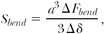 where
where
 is the slope of the measured bending force as a function of the bending deflection within its linear range as determined by linear fitting (Fig. 8.29). By determining the slope, the bending of the specimen due to gravitational force is also eliminated. The unit for Sbend is N mm2. Note that the bending stiffness depends on the cube of the bending length. Hence, the bending length a has to be determined very precisely. The propensity of a guiding catheter to kink can be measured as the bending deflection δ at which kinking occurs. Other relevant mechanical properties of the guiding catheters include crush resistance of the shaft, defined as a force needed to squash the catheter, and curve retention, measured as angle deviation from the original form following a defined amount of use. Examples of measured flexural stiffness of different guiding catheters are shown in Table 8-29 and Figure 8-30.
thin wire can be used to transmit the bending force onto the tested object. To allow objective definition of the bending process and to avoid sagging the bending length a has to be small (a ≈ 50 mm or smaller). At small δ, Fbend exhibits a linear dependence on bending deflection δ. Thus, for δ ≤ 0.1a, the flexural stiffness Sbend can be calculated as
TABLE 8-28. Gauge, Inch, and Millimeter Sizes of Puncture Needles | ||||||||||||||||||||||||||||||||||||||||||||||||||||||||||||
|---|---|---|---|---|---|---|---|---|---|---|---|---|---|---|---|---|---|---|---|---|---|---|---|---|---|---|---|---|---|---|---|---|---|---|---|---|---|---|---|---|---|---|---|---|---|---|---|---|---|---|---|---|---|---|---|---|---|---|---|---|
| ||||||||||||||||||||||||||||||||||||||||||||||||||||||||||||
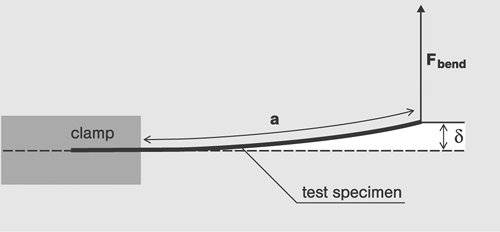 FIGURE 8-28. Diagram for measuring flexural stiffness in a two-point arrangement. The value a is the bending length, δ the bending deflection, and Fbend the bending force. The left end of the specimen has to be horizontally clamped in a careful manner, e.g., without changing the sectional shape in case of catheters. (Courtesy Dr. Wünsche, Kunstoff-Zentrum, Leipzig.) |
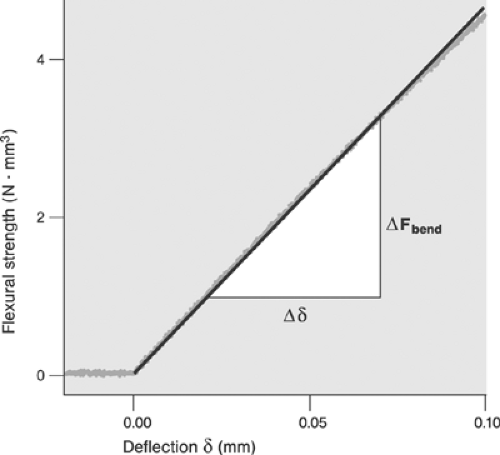 FIGURE 8-29. Measurements from a two-point bending test of a thin guiding wire. The noisy curve represents the measuring points. The straight line is a linear fit according to the equation 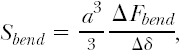 |
Purpose
Guiding catheters (guides) provide a transport corridor for the delivery of endovascular devices to the ostium of the target vessel, improve the steering of the endovascular devices, and ensure their backup during interventions. To perform well, guiding catheters are expected to provide:
Optimal shape to accommodate the topography of the aortic arch and target vessel ostia of individual patients
Atraumatic ostial seating and, if needed, endoluminal insertion
Stable backup and shape retention even in difficult and lengthy procedures
Resistance to kinking and compression
Large internal diameter for delivery of large instruments and small outer diameter to minimize injury to the access site
Low friction of the luminal interface
Low thrombogenicity and high biological compatibility.
TABLE 8-29. Flexural Stiffness of Four Dilatation Catheters | ||||||||||||||||||||||||||||
|---|---|---|---|---|---|---|---|---|---|---|---|---|---|---|---|---|---|---|---|---|---|---|---|---|---|---|---|---|
| ||||||||||||||||||||||||||||
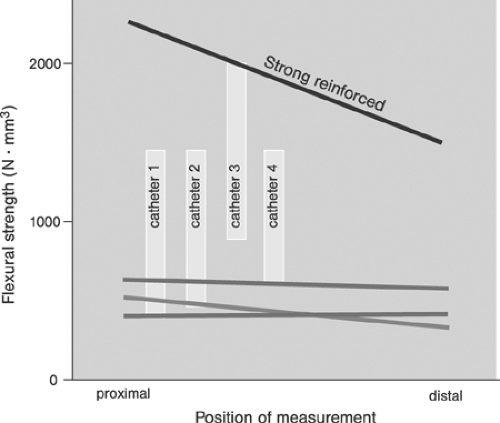 FIGURE 8-30. Flexural stiffness of 8F guiding catheters (upper line) compared with 6F catheters. (Courtesy Dr. Wünsche, Kunstoff-Zentrum, Leipzig.) |
Material, Design, and Form
Two basic designs of guiding catheter tubes are available: conventional and full wall. In the conventional design, the tube of the guiding catheter consists of three layers:
An outer jacket manufactured from a soft and smooth material, such as nylon, polyester elastomer, silicone
A braid of round or flattened stainless steel wire
An inner jacket made of the same material as outer jacket and coated with a low-friction material such as Teflon (polytetrafluoroethylene, PTFE) or silicone.
To increase flexibility and torque transmission while maximizing resistance to kinking and compression in full-wall technology, the inner and the outer layers are molded together with a flat wire braid encapsulation. To reduce friction, the internal surface of the polymer is typically covered with silicon. To improve visibility, barium sulfate, barium carbonate, or bismuth is added. To accommodate the different needs for optimal backup (see the later discussion of secondary curve), for which greater stiffness is required, and atraumatic ostial insertion (primary curve), for which a soft tip is required, several transitional zones of gradually changing stiffness are implemented. Figure 8-31 shows the walls of a guiding catheter in conventional and full-wall design. Figure 8-32 shows an example of the transitional zones at the catheter’s distal end.
Standard guides are 100-cm (90- to 115-cm) long tubes whose outer diameter ranges from 5F to 10F. They consist of a proximal hub, a long straight segment, and a shaped coaxial segment. The straight shaft is primarily responsible for torque transmission and resistance to kinking and compression during positioning. The configuration and shape of the coaxial segment of the transitional zones and the coaxial segment with the tip are, in contrast, decisive determinants of the backup and ostial seating. A number of catheter forms and shapes have been designed and implemented to ensure optimal seating and backup while accommodating the specific anatomy of the aortic arch and topography of the coronary ostia. The basic catheter forms employed in coronary interventions have been designed by Mason Sones,181 Melvin Judkins,182 and Kurt Amplatz.183 The classical Judkins left and right coronary catheter configurations are shown in Figure 8-33. These classical designs have been redesigned and modified by numerous engineers and operators. Still, new designs continue to surface, improving intubations of difficult ostia, coaxial seating, or catheter backup. To allow residual perfusion of the target vessel during interventions, the coaxial segment of the guide may carry side holes. Drawbacks of side holes are the greater use of contrast agents (50% to 80%), lower image quality, and potential of damaging guidewire tips. Guides with particularly soft or short tips are available to allow atraumatic ostial positioning in patients with severe proximal disease.
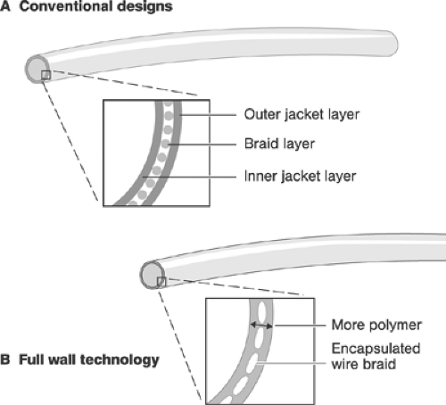 FIGURE 8-31. Guiding catheter walls in conventional and full-wall design. |
The French size of the guiding is the primary determinant of flexural stiffness, torque transmission, and kinking and crushing propensity. The internal diameter, in contrast, is the factor determining the maximum diameter of the deliverable endovascular instrumentation. Although the majority of PCIs are performed using 6F guides, 5F guides are fully adequate for straightforward interventions. Technically more demanding procedures usually require 7F size systems. Table 8-30 shows comparisons of the internal diameters of selected guiding catheters. For “double balloon” techniques, guiding catheters with a minimum internal diameter of 0.071 in. are needed; however, guides with bigger internal diameters are usually selected for greater comfort and better imaging.
The suitability of a specific guiding catheter for a given patient depends on the degree of concordance between the mechanical properties that are required and provided. Criteria for selection include:
Access site (majority of guides are designed for the transfemoral approach and accommodate the anatomy of the vascular access path and transmission of forces from this access site best)
Expected complexity of the case (a bigger French size provides greater freedom in executing the PCI process and usually works better in difficult cases)
Anatomy of the aortic arch and of the target ostium (consider using special guiding catheter forms and shapes for special cases, but try the simplest shape first)
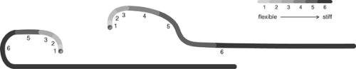
FIGURE 8-32. Transitional zones of two different guiding catheters.
Expected necessary backup (consider extra-support shaped catheters with optimal shape retention and catheters allowing deep seating for difficult cases in which a greater use of force may be required)
Standard catheter shapes are usually adequate for the majority of patients. In patients in whom the anatomy of the vascular access pathway is difficult or aberrant, however, special catheter forms and shapes as well as longer sheaths, which provide additional support, may be required. In selecting the catheter shape, standard recommendations should be followed (Table 8-31); in difficult cases, the trial-and-error approach represents the strategy of last resort. In difficult anatomy or high-crossing-resistance stenoses or occlusions, guiding catheters with extra support can be useful. These catheters provide stronger backup because they exert more pressure horizontally on the aortic wall opposite the ostium. Examples of extra-support guiding catheter shapes are the EBU configuration for the left coronary ostium and ECR configuration for the right coronary ostium (both Medtronic, Santa Rosa, CA, USA). However, the operator must take extra caution in seating these catheters because of the higher risk of ostial dissection.
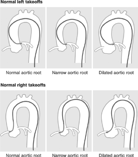 FIGURE 8-33. Left and right Judkins catheters. |
Optimal seating of the guide is characterized by a perfect coaxial alignment with the ostium and the proximal segment of the target vessel and flexible, yet firm ostial intubation. Seating that is too firm bears the danger of dissections with their inevitable consequences, whereas seating that is too loose or misalignments may cause poor backup, dislocations, and instability during the procedure. In patients with ostial stenoses or spasms and in unstable patients, guiding catheters with side holes may be required, which allow continuous coronary perfusion at the expense of poorer coronary artery visualization, greater contrast medium consumption, and potential guidewire damage. The robustness of the system is primarily determined by the French size; backup is also the result of the overall stiffness of the primary and secondary curves (greater stiffness provides greater backup). Interplay between degrees of stiffness and flexibility of the primary and secondary curves determines the propensity of the catheter for passive (peripheral ostial) or active (deep ostial) seating. A softer primary curve and stiffer secondary curve allow for deep intubation while retaining reasonable backup. With active seating, the risk of traumatization increases with the stiffness and French size of the guide. For example, selecting a 6F instead of a 5F Z2 and Launcher guiding catheter increases the stiffness of the coaxial segment by 33% and 64%, respectively. Objective ranking of the relevant mechanical properties of guiding catheters by noncommercial certified institutions would be helpful in improving our understanding of their handling and selection. Table 8-32 provides an example of ranking of three commercially available guiding catheters. Furthermore, operators would welcome industry support for a standardized set of indicators of the clinical performance of guiding catheters, which could be contained in marketing
information improving selection. The notion of “one size fits all” may work for standard PCI cases, but not for difficult ones. A set of performance indicators could include measures of length (cm), shape, internal and external diameters (in inches and millimeters), measures of stiffness and the rate of change of stiffness of the shaft, coaxial segment, and the tip, thermostability, resistance to kinking, and shape retention. Until more objective data on individual products become available, careful assessment of the clinical performance of individual products remains the only option. Table 8-33 summarizes some of the advantages and limitations of 5F, 6F, and 7F guiding catheters.
information improving selection. The notion of “one size fits all” may work for standard PCI cases, but not for difficult ones. A set of performance indicators could include measures of length (cm), shape, internal and external diameters (in inches and millimeters), measures of stiffness and the rate of change of stiffness of the shaft, coaxial segment, and the tip, thermostability, resistance to kinking, and shape retention. Until more objective data on individual products become available, careful assessment of the clinical performance of individual products remains the only option. Table 8-33 summarizes some of the advantages and limitations of 5F, 6F, and 7F guiding catheters.
TABLE 8-30. Comparisons of Internal Diameters of Selected Guiding Catheters | ||||||||||||||||||||||||||||||
|---|---|---|---|---|---|---|---|---|---|---|---|---|---|---|---|---|---|---|---|---|---|---|---|---|---|---|---|---|---|---|
|


