where
 is the longitudinal relaxation time of blood without Gd, T 1 is the shortened longitudinal relaxation time of blood in the presence of Gd, and R 1 is the relaxivity of Gd, which is multiplied by the concentration of [Gd].
Since the gadolinium itself is highly toxic, it must be chelated before it can be injected into the vessels. Currently there are several different chelates widely used for first-pass CE-MRA including Gd-DTPA (Magnevist), gadodiamide (Omniscan), gadobenate (Multihance), and gadobutrol (Gadovist). These compounds are permeable through the blood vessel walls, enhancing tissue signals as well. Chelates that are not permeable through the vessel walls, called intravascular agents, also exist (gadofosveset trisodium).
Gadofosveset trisodium (sometimes referred to by trade names, Vasovist and Ablavar) is a gadolinium-based, T1-shortening contrast agent that, unlike other Gd chelates, binds reversibly to serum albumin, in a proportion of 80–90 % for humans [13]. In 2010, it obtained FDA approval for MRA in the United States and has been used for over a decade in Europe for angiographic applications. Albumin binding hinders leakage of gadofosveset, and increases its half-life, so that the T1 shortening effect is observed up to 4 h post-injection, and interpretable steady-state images can be obtained up to an hour post injection [13]. The reversible binding allows excretion through the kidneys, or uptake by hepatocytes [14]. Excretion of unbound agent by the kidneys makes repeat injections feasible, unlike with other intravascular contrast agents [15].
The albumin bond also slows down the rotation rate of the complex, which enhances its relaxivity (T1-shortening effect, in mmol/L/s) six to ten times compared to other non-binding Gd-chelates [13], and four to tenfold compared to unbound gadofosveset [14]. As consequence of the high relaxivity/relaxation rate 1/T1, and the long half life in the blood vessels, the gadofosveset dosage necessary for high quality perfusion imaging is much lower than that of Gd-DTPA (0.03 mmol/kg vs 0.1 mmol/kg).
Gadofosveset is particularly advantageous to MRA, because images can be acquired with the first pass of the contrast agent bolus, as well as in steady-state (1–5 min to up to 1 h post injection) [16]. Steady-state MRA with gadofosveset allows the acquisition of bright, high resolution images of the smaller branches of the vasculature [17].
Ferumoxytol
Ferumoxytol is an ultrasmall paramagnetic iron oxide (USPIO) which has obtained FDA approval as an injectable iron supplement for the treatment of severe anemia in patients with advanced kidney disease. It has been used off-label as a MRA blood pool agent, in the imaging of the carotid arteries, thoracic and abdominal aorta, and peripheral vessels. Initial studies have shown the feasibility of first-pass and steady-state MRA in humans, with the initial concentration of 537.2 μmol elemental Fe/mL diluted four (134.3 μmol Fe/mL) or eightfold (67.1 μmol Fe/mL). The highest dose for MRA was 71.6 μmol/kg, injected at a rate of 1 mL/s. Dilution of the contrast agent minimizes its marked T2* shortening effects, which can lead to signal loss [18, 19].
Injection
Contrast agent is injected as a bolus during the scan using a power injector, which delivers an accurate dose and injection rate. Typically, 0.1 mmol/kg (considered single dose) is injected at 0.5–5 mL/s. Saline flush immediately follows to clear the venous access and push the contrast agent further into the circulation.
Due to the time delay between bolus injection and the appearance of contrast in the vessels of interest (passage of bolus from venous system to the heart, lungs, and aorta), conventional CE-MRA protocols required an initial timing run to measure lag time in order to precisely align the acquisition of the center of k-space to the peak of the bolus, thereby maximizing SNR. However, with radial acquisition with sliding window reconstruction, no timing of the injection is necessary because each radial line transverses the center of k-space. This will be discussed in further detail below.
Bolus Timing and Venous Overlay
Typically, a 20 mL bolus of contrast agent is injected into the veins over a short time interval (5–10 s). The goal of arterial CE-MRA is to image the maximum arterial enhancement, achieved when the injection bolus first passes through the artery of interest at its peak concentration. Therefore, acquisition speed is the main design criterion for first-pass CE-MRA pulse sequences. Usually, CE-MRA pulse sequences are spoiled gradient-echo pulse sequences that minimize TE and TR, and very often use partial k-space acquisitions in two or three directions. CE-MRA venography does not have this time constraint, which permits the acquisition of high SNR and spatial resolution images after the veins enhance.
Single phase CE-MRA sequences use the entire acquisition time to obtain data for one set of 3D images, in order to increase spatial resolution and coverage. This method requires timing of the bolus arrival, typically using a test bolus or fluoroscopic triggering (bolus tracking).
Time-resolved MRA images the volume of interest at different moments in time, which allows visualization of the various stages of signal enhancement in the vessels. Time resolved MRA frees the operator from having to measure the bolus circulation time (time from injection to peak arterial enhancement in the vessel of interest). However, since multiple acquisitions of the imaging volume have to be performed into a time interval comparable to the circulation time of the bolus, acquisition speed is even more important than in single phase CE-MRA. To decrease acquisition time, parallel imaging (SENSE) or partial k-space updating methods such as keyhole imaging or TRICKS are used. The keyhole method updates the center of k-space periodically, while TRICKS reacquires high-spatial- frequency data that contain the imaging information on small vessels.
Basic CE-MRA Technique
Data Acquisition
SPoiled Gradient Recalled echo (SPGR) sequence is used for CE-MRA. SPGR pulse sequences are T 1-weighted making them well suited for imaging the T 1 shortening effects of gadolinium contrast agent. Additionally, the short TR and TE in SPGR sequences enable them to image the fast moving contrast bolus [20]. Multiple phases or repetitions are acquired for dynamic imaging. Often, a pre-contrast volume is acquired before injecting the contrast agent bolus for subtraction in order to isolate the vessels from the background tissues. The MR acquisition is extremely lengthy compared to X-Ray angiography. A typical protocol of TR = 3 ms, 192 × 192 pixel resolution, and 24 slices results in almost 14 s of acquisition time just for a single volume. Even with the lengthy acquisition time, the spatial resolution and signal-to-noise ratio cannot match those of X-ray angiography. Section below will address the improvements to accelerate the acquisition of MRA data.
Gradient Echo Imaging
Spoiled GRE
SPGR sequences are known by different names, depending on the vendor: spoiled gradient echo (SPGR), T1 fast field echo (T1-FFE), and Fast Low-Angle Shot (FLASH). In each TR interval, the RF excitation converts the longitudinal magnetization into transverse magnetization, which is rephased by a gradient echo. If perfect spoiling is achieved, the transverse magnetization is zero before the new TR begins (there is no residual transverse magnetization from previous TR intervals). After a sufficient number of excitation pulses are applied, the longitudinal magnetization reaches steady state, and the FLASH signal at steady-state is dependent on T1, T2* and the flip angle:
 The FLASH signal is maximized at a flip angle called the Ernst angle:
 Since the Ernst angle increases monotonically as the ratio TR/T1 increases, TR values much shorter than T1 are an advantage, not a trade-off, to signal intensity. In SPGR sequences, much shorter TR values (TR<<T1) are possible compared to spin echo pulse sequences, since no lengthy period of time is required for T1 recovery.


Spoiling
Due to the short TR (TR << T1), of SPGR pulse sequences, residual transverse magnetization following each TR interval affects subsequent acquisitions thereby introducing a hybrid of T1 and T2 weighting to the image contrast. A combination of a time-varying gradients and RF phase cycling can be used to eliminate this effect. Gradient spoiling typically refers to a phase-encoding rewinder and a constant moment spoiler on the read-out axis. RF phase cycling shifts the RF excitation pulses according to a preset schedule. Spoiling in SPGR pulse sequences is addressed differently in non-Cartesian scans as the readout direction is changing with each projection acquisition. Spoiling residual transverse magnetizations equally at the end of each read out interval requires balancing of gradient moments. A simple method of accomplishing this may be to first rewind all gradients to the origin and subsequently wind the magnetization to the same point in k-space along the kx or ky axis. Two methods for doing this are shown in Fig. 20.1. This ensures the net magnetization at the end of each TR interval is at the same point in k-space [19].
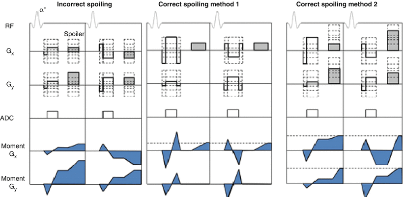

Fig. 20.1
Pulse sequence diagrams of consecutive projections in pseudorandom radial FLASH acquisitions showing examples of incorrect spoiling and two correct spoiling methods. Incorrect spoiling results in unbalanced gradient moments visualized in the blue shaded moment plots. The initial projection has a net positive moment accrual along Gx while the second projection has a net negative moment accrual along Gx. In each of the corrected spoiling methods, the magnetization is winded out to the same point in k-space resulting in balanced gradient moments among consecutive projections. In method 1, the Gx and Gy gradients are rewound and a constant spoiler is played along Gx. In method 2, the spoiler moment is adjusted in accordance with the projection angle, ensuring equal positive moments along Gx and Gy at the end of the TR interval
Balanced Steady-State Free Precession Imaging
Balanced steady-state free precession (bSSFP) (true-FISP: True Fast Imaging with Steady-State Free Precession; FIESTA: fast imaging employing steady-state excitation; FFE: balanced fast field echoes) is a method for performing flow-independent MRA. In bSSFP, image acquisition is sped up by recycling, instead of spoiling, the transverse magnetization after each TR. There are two conditions for achieving steady-state free precession: firstly, the RF pulses over several TR intervals have to have the same phase in the rotating frame, or a simple phase cycle such as sign alternation [21], and secondly, the phase accumulated by the transverse magnetization must be the same in each TR interval. To avoid dephasing of the transverse magnetization, the area under the gradient waveforms must be zero (gradients are completely balanced – see Fig. 20.2).
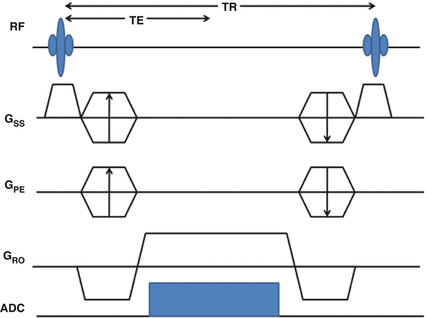

Fig. 20.2
Pulse sequence diagram for a balanced steady-state free precession (bSSFP) pulse sequence
The signal equation when steady-state has been achieved is given by the following equation:
 where
where  and
and 

 and
and 
The signal equation illustrates the T2/T1 contrast specific to bSSP imaging. Thus, media with large T2/T1, such as blood and fluids, will appear brighter in bSSFP images, which makes bSSFP naturally suitable for imaging blood vessel. The T2/T1 contrast can be further enhanced by choice of the optimal flip angle,  , with expected T1 and T2 of the tissue to be imaged. At the optimal flip angle, the signal amplitude is proportional to the square root of T2/T1:
 However, the same contrast mechanism makes other tissues with large T2/T1, such as fat, appear hyperintense, which requires the use of fat suppression methods during bSSFP imaging.
 , with expected T1 and T2 of the tissue to be imaged. At the optimal flip angle, the signal amplitude is proportional to the square root of T2/T1:
QISS
Quiescent interval single shot (QISS) [22] is a bSSFP-based, cardiac gated pulse sequence form MRA that takes advantage of the bright blood contrast in bSSFP while suppressing fat, venous inflow and background tissue. Following the ECG R-wave, 90° slice selective saturation pulses are played to null the longitudinal magnetization of tissues within the slice. Another 90° tracking pulse is played to saturate the venous spins. The quiescent interval corresponds to peak systolic flow, which allows the signal to be replenished by the inflowing spins of the arterial blood. The quiescent period is followed by a chemical shift – selective fat saturation RF pulse and an RF α/2 catalyzation pulse that forces the magnetization into steady-state free precession. bSSFP read-out follows these preparation pulses. A two-center trial in 53 patients referred for lower extremity MRA found QISS to have equivalent diagnostic accuracy as CE-MRA and DSA [1]. See Fig. 20.3 for multi station QISS images acquired without the use of contrast agent showing the vasculature from the abdomen to the pedal arch.
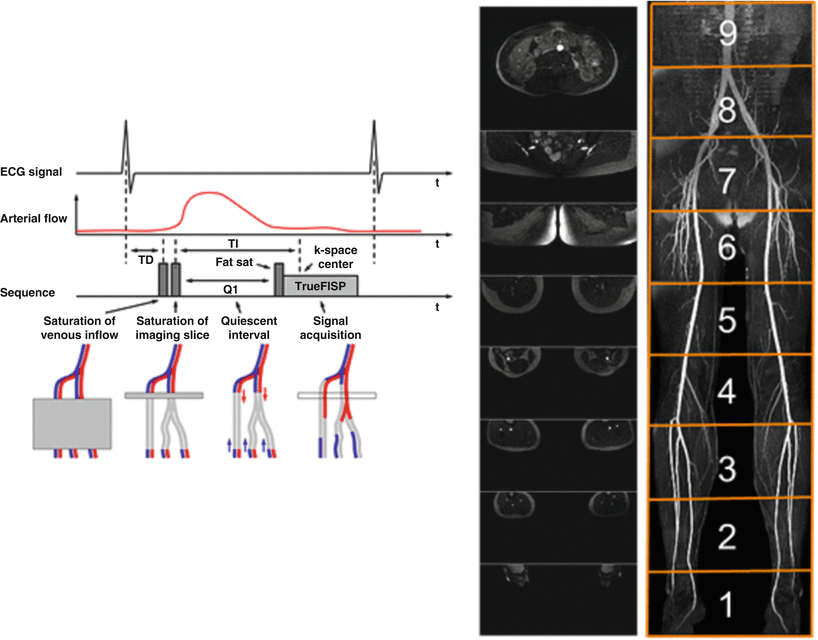

Fig. 20.3
Multi station QISS images acquired without the use of contrast agent showing the vasculature from the abdomen to the pedal arch (Images Courtesy of Dr. Robert Edelman, M.D.)
Data Reconstruction
The simplest data reconstruction of CE-MRA datasets begins with calculating the 2D Fourier transform of the Cartesian data. In the case of a 3D acquisition a 1D Fourier transform is performed as well in the slice direction. To depict blood vessels without tissue overlay, subtraction is utilized. Usually, the first volume is then subtracted from the subsequent volumes to subtract any background tissues. Maximum intensity projections (MIP), where the highest values are selected in the slice direction, are derived from the subtracted volumes to obtain images similar to X-Ray DSA.
Applications and Developments in CE-MRA
Many developments have been made and significant research is still in progress to improve the performance of CE-MRA. The ultimate goal is to replace the invasive X-Ray DSA, which has superior temporal resolution and image quality. The following improvements enabled faster acquisition, reduced artifacts, increased signal, and better dynamic information. Some of the improvements discussed here are well suited for CE-MRA, but are not limited to MRA and are applicable to other MR imaging techniques.
Partial Fourier
The simplest way of accelerating acquisition is acquiring less data in violation of the Nyquist criteria. Partial Fourier is a method to only acquire a fraction of the full k-space. The k-space consists of spatial frequency information in positive and negative directions. Most of the image energy is located in the lower spatial frequencies, close to the center of the k-space. Taking advantage of this idea, the k-space is acquired asymmetrically about the origin, as shown on Fig. 20.4, taking the high frequency data from only one side of the k-space. This idea can be used in all dimensions. Each echo can be asymmetrically sampled. Phase encoding steps can be reduced. For 3D imaging with Fourier encoding in slice direction, less slices can be image. The parts of k-space not acquired can be either zero-filled or calculated using the fact that the k-space representation of a real image is Hermitian, meaning the opposite side of the k-space is the complex conjugate of the other side. Filling the missing k-space using Hermitian symmetry is called homodyne method.
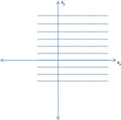

Fig. 20.4
Partial Fourier acquisition in k y and k x
However, partial Fourier results in decreased SNR, since high frequency noise variance is increased while the low frequency signal remains the same. Also it has been shown that zero-filled k-space have higher SNR than homodyne processed since high frequency components are not collected [23]. However, the homodyne method retains more high frequency information which may be useful. It has been reported that 62.5 % partial acquisition resulted in about 75 % decrease in SNR using homodyne method [24]. This may be an acceptable tradeoff when rapid imaging is of higher priority.
Acquisition Ordering
Instead of collecting data by linearly traversing the k-space, the acquisition order can be modified to optimize image quality. Centric acquisition collects the phase encoding lines starting from the center of k-space and outward in the order of proximity to the center. This ordering is useful when timing the bolus arrival since the center of k-space, which has most of the image energy, needs to be acquired at the peak phase. The centric scheme can be applied to both phase encoding and slice select directions. The elliptical-centric ordering takes centric acquisition further to 3D and acquires the data in the order close to the origin of k-space. In other words, the readout with the smallest  value gets acquired first [4]. Although the centric ordering schemes improve the imaging protocol by making it easier to time the peak contrast arrival, there are no substantial improvements in speed or image quality from the technique itself.
 value gets acquired first [4]. Although the centric ordering schemes improve the imaging protocol by making it easier to time the peak contrast arrival, there are no substantial improvements in speed or image quality from the technique itself.
Also utilizing the fact that the central parts of k-space contain more information, the Keyhole method is a technique that samples the center of k-space more often than the outer parts of the k-space [25, 26]. Initially, a full k-space image is acquired as a reference. Then for subsequent dynamic series only the central part of the k-space, or ‘keyhole data’, are imaged. Later, the keyhole data is combined with the high frequency data from the reference image using various methods. The keyhole technique increases the acquisition rate because it reduces the amount of high spatial frequencies acquired, but the high frequency components are never truly updated. High frequency information such as smaller vessels or aneurysms may be misrepresented.
Similar to Keyhole technique, the Time Resolved Imaging of Contrast KineticS (TRICKS) is another method [27] that samples the center of k-space more often than the outer regions. In this technique, the k-space is divided into sections, A, B, C, and D, for example, with the A section being the central part and B, C, and D sections being the outer parts, in order of proximity. The use of 3DTRICKS provided information as well has high quality non-invasive angiograms. In Fig. 20.5 a patient with a high grade carotid artery stenosis images with X-ray DSA and 3D TRICKS demonstrates the excellent depiction of a moderate stenosis in the distal carotid artery of a patient.
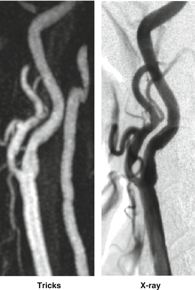

Fig. 20.5
Maximum Intensity Projection through a 3D image volume selected from the peak arterial phase of a 3D TRICKS image provides clinically relevant information on the presence of a carotid artery stenosis equivalent to more invasive X-Ray DSA (Images courtesy of Dr. Patrick Turski, M.D.)
Then the data is acquired in the order, ABACADABACAD…, until the end of the scan. This technique addresses the problem of not updating high frequency information in the Keyhole technique. But because of the extra acquisition time needed, TRICKS has not been shown to be fast enough for some applications, such as intracranial AVMs [28].
Parallel Imaging
Parallel Imaging, a technique used in all areas of MRI, is used to accelerate imaging time by using multiple coils that each acquire different information and later combine to form one image. Compared to using one coil or having multiple channels all acquire the same information and averaging the data, parallel imaging reduces the imaging time roughly by the factor of the number of channels since each channel only acquires a part of the image. In most cases, this is done by undersampling phase encodes, which produces aliased images. Then parallel reconstruction techniques are applied to extract an unaliased image. The techniques can be divided into two broad categories, image space and k-space techniques.
An image space technique, partially Parallel Imaging with Localized Sensitivities (PILS) [29] uses the prior knowledge of the coil sensitivities that cover distinct regions in image space phase encoding direction. Unaliased regions with reduced FOV are combined to form the final image. This technique is restricted to localized coil sensitivities, which leads to the discussion of Sensitivity Encoding, or SENSE [30]. The SENSE technique also uses prior knowledge of coil sensitivities which are not assumed to be localized. Each aliased pixel is a sum of intensities from different parts of the image, weighted by the coil sensitivity. Then, if the sensitivity weighting is known, a linear system with the number of equations and variables equal to the number of coils is derived. Solving this system yields the final image.
< div class='tao-gold-member'>
Only gold members can continue reading. Log In or Register to continue
Stay updated, free articles. Join our Telegram channel

Full access? Get Clinical Tree


