Computed Tomography Angiography in the Diagnosis of Vascular Disease
Paaladinesh Thavendiranathan
Michael Walls
Georgeta Mihai
Imaging of the peripheral vascular system became possible in the 90s with the introduction of 4-slice multidetector scanner with 0.5-second gantry rotation speed. Ongoing advances have led to increases in z-axis coverage with a single rotation and better temporal resolution. The most contemporary scanners include those with 320 detectors, with a gantry rotation speed of 350 ms (temporal resolution 175 ms), and dual source scanners with a temporal resolution of up to 42 to 83 ms. These advances have enabled rapid scanning at superior temporal and spatial resolution, and together, radiation reduction techniques have led to establishing multidetector CT angiography (MDCTA) as a viable and accurate modality in the assessment of vascular disease.
FUNDAMENTALS OF COMPUTED TOMOGRAPHY IMAGING
Major Components of a Computed Tomography Scanner
The major components of a CT scanner are an x-ray tube and generator, a collimator, and photon detectors. These components are mounted on a rotating gantry. The x-ray tube produces the x-rays necessary for imaging. The collimator helps shape the x-ray beams that emanate from the x-ray tube in order to cut out unnecessary radiation. The detectors consist of multiple rows of detector elements (greater than 900 elements per row in the current scanners), which receive x-ray photons that have traversed through the patient. The older generation scanners only had single detector row; however, the newer scanners have as many as 320 detector rows. With the increase in detector rows, the width of each detector has also decreased from 1.5 to 0.5 mm. The most important benefit of increasing the detector rows is the increased coverage per gantry rotation (a 320-row detector CT with a detector width of 0.5 mm will have coverage of 160 mm). Decreased detector width improves spatial resolution in the z axis, while increased coverage shortens scan time. The gantry rotation times determine the temporal resolution of the images with older scanners having a rotation time of 0.75 second, while the more contemporary scanners have a rotation time of 0.33 second. The temporal resolution of the CT image is half the time it takes for the gantry to rotate 360 degrees.
Attenuation Data for Image Reconstruction
Similar to other x-ray techniques, cardiac CT uses differences in attenuation in order to map and display anatomy. The gantry rotates around the patient collecting attenuation data from different angles. The attenuation
data obtained between 0 and 180 degrees will be identical, hence negating the necessity to obtain 360 degrees of data. The images displayed are a map of differences in relative attenuation that the x-ray beam experiences as it passes through the area of interest. Different objects have different attenuation properties described by its attenuation coefficient µ. This is an indicator of the likelihood that the x-ray photons will interact with an atom of the tissue rather than passing through it. This attenuation coefficient varies depending on the thickness of the material and the energy of the photons (measured in keV) that pass through them. The measured intensity of photons at the CT detector can be expressed using a formula (below) describing the relationship between the photon flux coming through the x-ray tube and that detected at the detector elements. “I” is the intensity measured at the detector, “Io” is the photon flux from the x-ray tube measured in milliamperes (mA), “e” is the exponent, and “µ” is the attenuation coefficient.
data obtained between 0 and 180 degrees will be identical, hence negating the necessity to obtain 360 degrees of data. The images displayed are a map of differences in relative attenuation that the x-ray beam experiences as it passes through the area of interest. Different objects have different attenuation properties described by its attenuation coefficient µ. This is an indicator of the likelihood that the x-ray photons will interact with an atom of the tissue rather than passing through it. This attenuation coefficient varies depending on the thickness of the material and the energy of the photons (measured in keV) that pass through them. The measured intensity of photons at the CT detector can be expressed using a formula (below) describing the relationship between the photon flux coming through the x-ray tube and that detected at the detector elements. “I” is the intensity measured at the detector, “Io” is the photon flux from the x-ray tube measured in milliamperes (mA), “e” is the exponent, and “µ” is the attenuation coefficient.
I = Ioe-m
Therefore, as the attenuation of the tissue increases, the fraction of photons that are detected at the detector element decreases. As these photons strike the scintillation crystals at the detector array, they are converted into light, which then strike photodiodes that convert light into digital signals. Therefore, during CT imaging, the photon energy (keV) and the photon flux (mA) are set by the user, the photon intensity at the detector is measured with the scintillation data, and using the formula described about the attenuation coefficient is back-calculated. This attenuation data is then “referenced” to the attenuation coefficient of water to generate a CT number, which is expressed in Hounsfield units. By default the CT value of water is set at 0, while CT value of air is -1,000.
CT number = [(µtissue — µwater)/uwater — µair] × 1,000
These CT values are “number behind the images” and are used to fill a “matrix” that consists of pixel elements. The most commonly used matrix size is 512 × 512 pixels in the x and y directions. This process of projecting these CT values into the matrix is referred to as back projection. Combination of multiple back projections with filtering is necessary to reduce noise and to increase the sharpness of an image. This process is referred to as filtered back projection. A grayscale window is then applied to this matrix generating tissues of different brightness depending on the CT values and the window settings. Where the CT values are higher, the image will be brighter and where the CT values are lower, it would be darker.
Scanning Modes
The two scanning modes used in CT are the axial mode and the spiral/helical mode. The major differences between these modes include (i) differences in table movement during image acquisition, (ii) differences in assignment of data to each channel, and (iii) need for interpolation for data reconstruction. Each mode has its benefits; however, the mode used for
vascular CTA is the spiral/helical mode. For coronary CTA, there has been a shift toward using axial mode due to its benefit in significantly reducing radiation exposure. In the axial mode, images are acquired at particular selected points in the cardiac cycle (ECG based) with the tube being turned off between images.
vascular CTA is the spiral/helical mode. For coronary CTA, there has been a shift toward using axial mode due to its benefit in significantly reducing radiation exposure. In the axial mode, images are acquired at particular selected points in the cardiac cycle (ECG based) with the tube being turned off between images.
Spiral/Helical Mode
During spiral scanning, there is continuous table movement and the tube is on the whole time; however, the tube current can be made to fluctuate. Since the table is moving during the acquisition, the detector channels are not dedicated to a slice of the patient and hence it receives data from multiple contiguous slices of the patient. An interpolation algorithm would be necessary to reconstruct “virtual” axial slices with some loss in image quality. Spiral imaging is fast and can provide infinite reconstruction of data, however, at the cost of higher radiation.
Pitch
Pitch is an expression of the relationship between the table speed of the scanner per gantry rotation and the coverage of the scanner. Pitch = [table feed per rotation (mm)/coverage (mm)]. If the pitch is 1, then there would be no gaps between the data set. However, if the pitch is greater than 1, gaps would be present, and if the pitch is less than 1, there would be overlap in the data acquisition. The pitch for ECG-gated cardiac scanning is 0.2 to 0.3. For most vascular CT, the pitch ranges between 0.5 and 1.2.
ECG Gating
ECG gating is a method of correlating changes in the heart or vascular structure to the cardiac cycle. It is mainly used for cardiac CTA and often for thoracic aortic imaging. The two most common ECG gating methods are retrospective and prospective gating. With traditional spiral scanning, the ECG gating is performed retrospectively where the data and ECG information are acquired and subsequent reconstructions can be performed at various time points in the RR interval. Whereas in prospective ECG gating, the scanner is usually triggered at the R wave and image acquisition occurs at a fixed point in the cardiac cycle. This is the method used for axial scanning. However, with recent advances in CT imaging, it is also now possible to perform prospectively ECG-triggered helical scans using high pitch with extremely low radiation exposure. These have been referred to as “flash” scans and are gaining significant popularity for coronary imaging.
General Acquisition Parameters
The selection of the specific acquisition parameters of imaging depends on the employed scanner model, the patient’s body habitus, and the clinical question. The two main adjustable parameters are the tube voltage and current. The voltage is typically set at 120 kilovolts (kV) although 100 kV provides acceptable images with significantly reduced radiation and can be employed in most individuals who are not obese for vascular imaging.
Tube current is usually 200 to 300 mA and again can be adjusted upward if the patient is very large. Breath-holding is required only for the chest and abdomen CTA acquisitions in order to reduce motion artifact. In MDCT spiral scans, the volume coverage speed (v, cm/s) can be estimated by the following formula:

where M = number of simultaneous acquired slices, scoll = collimated slice width, p = pitch, and trot = gantry rotation time. Although current generation scanners offer improved spatial resolution, their increased coverage and rotation speeds pose the risk of “outrunning” the bolus of contrast in CTA applications. Accordingly, adjustments in both the pitch and the gantry rotation speed must be made in order to achieve a table translation speed of no more than 30 mm/s for CTA applications. In a 64-slice scanner, this usually is achieved by a reduction in trot to 0.5 second and a decrease in pitch to ≤0.8.
Contrast Administration
Low-osmolar nonionic iodinated contrast agents are most commonly used for CTA applications. Patients’ renal function should be assessed prior to administration of contrast and decisions regarding prophylactic medication use should be made if necessary. The contrast agent is administered intravenously using a power injector into an antecubital vein, preferably on the right side. Since contrast arrival time may vary, appropriate timing could be determined using a small test bolus or an automated bolus-triggered technique. For most CTA applications, 100 to 120 mL of contrast (with an iodine concentration between 320 and 370 mg/mL) is administered at a rate of 4 mL/s followed by a saline flush. Although, the use of higher iodine concentration (370 to 400 mg/mL) contrast agents yields improved enhancement, there is likely no difference in diagnostic ability for vascular applications. When an automated bolusdetection algorithm is used for CTA, the region of interest (ROI) is placed in the part of the aorta close to the area of interest. A repetitive low-dose acquisition is performed at the monitoring location (e.g., ascending aorta for thoracic aorta CTA and suprarenal aorta for distal abdominal and lower extremity CTA) and is started approximately 5 to 10 seconds after contrast injection begins. The actual angiographic acquisition is started when the contrast enhancement reaches a prespecified Hounsfield unit threshold (e.g., 110 HU).
Image Reconstruction at the Scanner Console
Various image reconstruction filters are offered by each manufacturer. These filters are referred to as “sharp” or “soft” filters. Sharper reconstruction filters will provide more details but also more noise and are best for assessment of stents and areas of calcifications. Softer reconstruction filters provide less image detail but less noise as well. Soft to medium filters are
usually used for most CTA applications. Image reconstruction can also be performed at different phases in case of cardiac-gated acquisitions and may be important in assessment of coronary anatomy in cases of dissections or concomitant assessment of coronary artery/graft anatomy in cases of thoracic aortic aneurismal disease. This is most important for cardiac CTA where coronary anatomy may need to be assessed at different phases to ensure accurate delineation of coronary stenosis. When ECG-gated thoracic aortic image is performed, various phases can be reconstructed to assess the aorta.
usually used for most CTA applications. Image reconstruction can also be performed at different phases in case of cardiac-gated acquisitions and may be important in assessment of coronary anatomy in cases of dissections or concomitant assessment of coronary artery/graft anatomy in cases of thoracic aortic aneurismal disease. This is most important for cardiac CTA where coronary anatomy may need to be assessed at different phases to ensure accurate delineation of coronary stenosis. When ECG-gated thoracic aortic image is performed, various phases can be reconstructed to assess the aorta.
Slice width and slice increment used for image reconstruction at the scanner console depend on the anatomy being assessed and scanner capabilities. Reconstruction thickness for vascular imaging can be performed at the same width (thin) or several times the detector width (thick) to reduce noise (thinner slices are associated with higher image noise compared to thicker slices and take longer time to review). A slice increment of approximately 50% of the slice thickness is used.
Image Postprocessing
Similar to vascular MRA (Chapter 4), multiple postprocessing techniques can be used in vascular CTA to assess the thousands of images that are generated. Usually, two data sets are reconstructed including “thick” and “thin” sets. The thick set (5.0 mm) is used for general assessment, whereas the thin set (0.6 to 0.75 mm) is more suited for detailed evaluation. Image formats used for evaluation include (i) multiplanar reformats (MPR), (ii) maximal intensity projections (MIPs), (iii) curved planer reformats (CPRs), (iv) volume rendering (VR), and (v) shaded surface display. Please refer to the vascular MRA section for description of these techniques. For CTA, the evaluation of the data set begins with review of the axial images to assess gross anatomy and scan quality. This is followed by use of a MIP format in traditional projections as well as in oblique projections. Care must be taken in viewing MIP images when calcium is present, as it can overestimate the severity of stenotic lesions. For detailed evaluation, especially when calcium and stents are present, the raw MPR images should be reviewed. Curved planar reconstruction is a unique technique that makes it possible to follow the course of any single vessel and displays it in nontraditional plane where the entire vessel can be seen in a single image. 3D-VR images can also be reviewed to define anatomic course and anatomic variations if necessary. Each of these reconstruction methods has its pitfalls and it is important to assess an abnormality identified in a systematic manner, in multiple different planes, using different techniques, and different phases of the cardiac cycle if available.
Radiation
Radiation exposure of the patient during a CT exam and the resulting potential radiation hazards has gained considerable attention in the public and the scientific literature. The Bier VII committee states that “there is a linear no-threshold dose response relationship between exposure to ionizing radiation and cancer risk.” This has resulted in the adoption of the ALARA
(As Low as Reasonable Achievable) principle in the use of radiation-based diagnostic studies. Typical effective dose of radiation for CT protocols vary from 1 to 2 mSv for a head examination, 2 to 3 mSv for CT pulmonary angiography, 4 to 6 mSv for a nongated thoracic CTA, and 6 to 10 mSv for a coronary CT (64 detector scanners, with ECG dose modulation). This must, however, be considered in the context of the average annual background radiation exposure worldwide of approximately 2.4 mSv/y and the radiation exposure from an alternative diagnostic modality. The radiation exposure depends on many factors including scan factors such as coverage, slice thickness, pitch, ECG gating, tube voltage, and tube current, and patient factors such as BMI and heart rate. It is therefore incumbent upon the physician supervising the study to individualize scan protocols to ensure a diagnostic study while minimizing radiation exposure.
(As Low as Reasonable Achievable) principle in the use of radiation-based diagnostic studies. Typical effective dose of radiation for CT protocols vary from 1 to 2 mSv for a head examination, 2 to 3 mSv for CT pulmonary angiography, 4 to 6 mSv for a nongated thoracic CTA, and 6 to 10 mSv for a coronary CT (64 detector scanners, with ECG dose modulation). This must, however, be considered in the context of the average annual background radiation exposure worldwide of approximately 2.4 mSv/y and the radiation exposure from an alternative diagnostic modality. The radiation exposure depends on many factors including scan factors such as coverage, slice thickness, pitch, ECG gating, tube voltage, and tube current, and patient factors such as BMI and heart rate. It is therefore incumbent upon the physician supervising the study to individualize scan protocols to ensure a diagnostic study while minimizing radiation exposure.
CLINICAL APPLICATIONS OF COMPUTED TOMOGRAPHY ANGIOGRAPHY IN VASCULAR DISEASE
Computed Tomography Angiography of the Extra Cranial Circulation
Technical Considerations
To perform CTA of the cervicocranial arteries, the patient is placed in the supine position with upper arms along the body. A topogram is first performed to assist planning of the imaging volume. The scan volume should include the aortic arch to the level of the circle of Willis. A submillimeter detector collimation is preferable. Tube current and voltage is vendor dependent. A test bolus or a bolus tracking algorithm can be used for synchronizing contrast arrival and initiation of scanning. Thin collimation (= minimal detector width) should be used whenever possible to achieve high z-axis spatial resolution. The pitch can range between 0.5626 and 1.0 depending on the vendor and the number of detector rows. Breath-holding is recommended especially for better assessment of the aortic arch vessels, and the patient should be asked to not swallow during the study. Reconstruction of the acquired images should be performed using a smooth reconstruction kernel (e.g., Siemens B20f). Reconstructions slice thickness of 0.6 to 1.0 mm with a 50 to 80% reconstruction increment is often used for assessment of the carotid circulation.
Clinical Application
Atherosclerotic and Nonatherosclerotic Disease
The most common indication for CTA of the extracranial circulation is for the evaluation of suspected carotid stenosis due to atherosclerosis (Fig. 5.1A). CTA is also an important component of the comprehensive evaluation of a patient with acute stroke coupled with nonenhanced brain CT and perfusion imaging. Other nonatherosclerotic diseases such as fibromusclar dysplasia, carotid aneurysms or pseudoaneurysms, or dissection in the carotid, subclavian, or vertebrobasilar systems can also
be assessed with high spatial resolution. CTA also has a unique role for the follow-up after carotid endovascular stenting (Fig. 5.1B and C) over MRA due to its ability to assess complications such as dissection and in-stent restonosis and the lack of susceptibility artifacts that would be seen with MRA. CTA is accurate compared to digital subtraction angiography for the identification of total or near occlusions of the carotid artery, and for the identification of location of the stenosis; however, it may underestimate and sometimes overestimate stenosis severity. There are also other limitations with CTA including assessment of calcified segments and their associated artifacts and inability to assess flow dynamics.
be assessed with high spatial resolution. CTA also has a unique role for the follow-up after carotid endovascular stenting (Fig. 5.1B and C) over MRA due to its ability to assess complications such as dissection and in-stent restonosis and the lack of susceptibility artifacts that would be seen with MRA. CTA is accurate compared to digital subtraction angiography for the identification of total or near occlusions of the carotid artery, and for the identification of location of the stenosis; however, it may underestimate and sometimes overestimate stenosis severity. There are also other limitations with CTA including assessment of calcified segments and their associated artifacts and inability to assess flow dynamics.
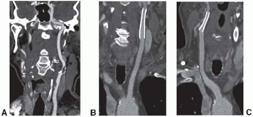 FIGURE 5-1. A: Curved planar reconstruction from the left carotid artery illustrating stenosis with a mixed plaque at the bifurcation and an ulcerated plaque at the common carotid. (B) Postprocedural CT angiography of another patient showing curved planar reformations of stents in the right external carotid artery (C) and in the left internal carotid artery (Reprinted from Berg M, Kangasniemi M, Manninen H, et al. CT angiography of the extracranial and intracranial circulation with imaging protocols. In: Mukerjee D, Rajagopalan S, eds. CT and MRI angiography of the peripheral circulation: practical approach with clinical protocols. London, UK: Informa Health Care, 2007:67-69, with permission.) |
Computed Tomography Angiography of the Pulmonary Artery
Technical Consideration and Clinical Applications
CT of the pulmonary arteries (CTPAs) is the diagnostic test of choice for the assessment of pulmonary thromboembolic disease. Specifically when combined with CT venography of the proximal lower extremities, CTPA has high sensitivity and specificity for the diagnosis of pulmonary embolus (Fig. 5.2


Stay updated, free articles. Join our Telegram channel
Full access? Get Clinical Tree
