Computed Tomographic Angiography of the Abdominal Arteries
Rutger W. van der Meer
Lucia J.M. Kroft
Jasper Florie
Martin N. Wasser
Albert de Roos
ABDOMINAL COMPUTED TOMOGRAPHIC ANGIOGRAPHY TECHNIQUES
Computed tomography (CT) has undergone a revolution since the introduction of multidetector-row computed tomography (MDCT) using systems currently up to 320 detector arrays (1,2,3,4 and 5). MDCT has three main advantages compared with single-slice CT: Faster imaging, the ability to cover larger body volumes, and thinner section thickness with improved image quality (6). Computed tomographic angiography (CTA) has gained wide acceptance with the introduction of MDCT. Faster imaging results in substantial reduction of acquisition time (7). Imaging of the abdominal aorta and iliac arteries can be performed in approximately 20 seconds with a 4-row MDCT (depending on slice thickness and volume coverage) and in usually less than 10 seconds with a more than 4-row MDCT, thereby generating less motion artifacts because of imaging in a single breath-hold and less pulsation artifacts because of reduced rotation time. The possibility to cover larger anatomic areas allows for new applications, such as evaluation of the entire thoracoabdominal aorta in a single breath-hold and imaging of the aortoiliac system and lower extremities in one acquisition with high spatial resolution (7). Thinner section thickness improves image quality and allows acquisitions with isotropic or near isotropic spatial resolution (1,7). Three-dimensional (3D) visualization can facilitate image interpretation and might improve diagnostic accuracy.
MDCT is superior to single-slice CT for nearly all applications, especially for imaging the vascular system (1,8). Compared with single-slice CT, there is a reduction in radiation dose, except when thin sections of high quality are acquired or when multiphase imaging is performed (3). Compared with single-slice CT, the injected volume of contrast medium can be reduced substantially by using more than 16-row MDCT technology.
MDCT has replaced x-ray angiography in many clinical vascular applications (6). Furthermore, current MDCT technology has a better spatial resolution than magnetic resonance imaging (MRI). Another advantage of MDCT for vascular imaging is that mural calcifications can be assessed, which are usually not well recognized with MRI. Disadvantages of CT are the use of ionizing radiation and the administration of a potentially nephrotoxic iodinated contrast medium.
In this chapter the abdominal CTA technique will be discussed. Practical applications of MDCT for assessing the abdominal aorta and renal and mesenteric vessels will be reviewed.
CONTRAST ADMINISTRATION
Intravascular contrast material administration is essential in CTA (6). Both technical factors and patient-related factors affect the process of contrast enhancement. It is important to achieve homogeneous intravascular enhancement during imaging. Arterial enhancement depends on iodine concentration of the contrast medium used and the injection protocol (9). More enhancement is achieved with higher iodine concentration. Faster injection rates rather than increased contrast medium volume also provide more enhancement, because a higher concentration of iodine is injected over time (9).
Several contrast injection protocols have been used for CTA. Uniphasic injection protocols with fixed scan delay, injection volume, and injection rate usually result in sufficient aortic enhancement (10). An interactive protocol, in which
the injection of contrast medium is stopped manually, can be used to reduce the volume of contrast medium administered (11). Uniform, plateau-like arterial enhancement can only be achieved using a biphasic injection protocol (12). A biphasic injection protocol starts with a small bolus with a high flow rate, followed by a larger bolus with a lower flow rate (12). A saline flush is recommended to flush the veins and push the contrast column into the circulation to reduce the amount of contrast agent (6). Contrast injection for abdominal imaging is preferably administered in a cubital vein.
the injection of contrast medium is stopped manually, can be used to reduce the volume of contrast medium administered (11). Uniform, plateau-like arterial enhancement can only be achieved using a biphasic injection protocol (12). A biphasic injection protocol starts with a small bolus with a high flow rate, followed by a larger bolus with a lower flow rate (12). A saline flush is recommended to flush the veins and push the contrast column into the circulation to reduce the amount of contrast agent (6). Contrast injection for abdominal imaging is preferably administered in a cubital vein.
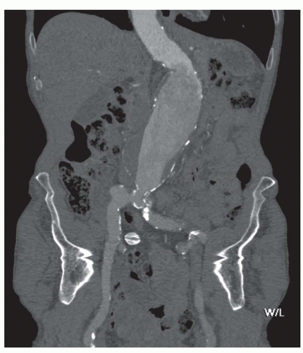 Figure 34.1. Coronal curved planar reformation (CPR) presentation in the abdominal aorta and right iliac artery in a patient with an abdominal aortic aneurysm (AAA). Inhomogeneous enhancement in the abdominal aorta and iliac arteries because of turbulent flow. |
Major patient-related factors determining contrast enhancement are body habitus and cardiac status. In case of an abdominal aortic aneurysm (AAA), enhancement can be inhomogeneous because of turbulent flow (Fig. 34.1). Because of these and other differences in circulation dynamics between patients, scanning with a fixed delay is not recommended (12). In addition contrast volume and injection rate need to be adjusted according to patient weight to achieve optimal vascular enhancement. Solutions to optimize scan delay for determination of the optimal enhancement phase in a single patient are bolus triggering and the use of a test bolus. With the first technique, a region of interest is placed in the distal descending aorta for abdominal CTA. During contrast injection, low-dose nonincremental scans are obtained in a dynamic fashion. The attenuation is monitored in the region of interest and when a predefined enhancement threshold is reached, for example, 150 HU, the CT scan starts automatically with a delay of a few seconds, depending on the type of CT scanner (6). The second technique uses a test bolus to determine patients’ contrast transit time. A region of interest is placed in the distal descending aorta for abdominal CTA and during injection of 15- to 20-mL contrast medium, the test bolus, a series of low-dose nonincremental CT scans are obtained. An enhancement curve is then automatically calculated, and the time to maximum enhancement equals the mean contrast transit time. The time to maximum enhancement is set as the scan delay. However, scanning should be started after an extra delay of approximately 10 seconds, because with a large contrast bolus maximum enhancement is achieved later compared with a test bolus because of the accumulation of the contrast agent in the blood vessels (6).
With shorter acquisition times, the amount of contrast agent to be injected can be reduced, but higher injection rates are required for optimal enhancement. When parenchyma imaging is also required (e.g., in liver imaging), the volume of contrast medium cannot be reduced, because enhancement of the parenchyma depends on the total iodine dose (9).
Oral contrast administration is not advisable for vascular imaging; superposition of bowel loops filled with contrast medium can hamper the evaluation of the contrast-enhanced blood vessels, especially when reconstructions are obtained. However, when oral contrast administration is required for imaging, negative contrast medium (e.g., water) can be used, which will not disturb evaluation of the contrast-enhanced blood vessels. In addition, the use of negative oral contrast agents facilitates assessment of the bowel wall when bowel ischaemia is suspected.
SCANNING TECHNIQUE
Vascular imaging of the abdominal aorta and its side branches requires a high-resolution protocol to produce a (near) isotropic dataset of thin overlapping cross-sectional images. Two-dimensional (2D) and 3D reconstructions of high quality can be produced from this dataset. With 4- or 16-row MDCT, section thickness of 1 to 1.25 mm and 1 mm, respectively, can be obtained for high-resolution scanning. With thinner section thickness, scanning is not fast enough for covering the entire body volume of interest, whereas with 64-row MDCT, section thickness of 0.5 mm can be obtained routinely.
Our standard scan protocol for the Aquilion 64 (Toshiba Medical Systems, Toshiba cooperation, Tokyo, Japan) for the abdominal aorta and mesenteric vessels is performed in the supine position, with the arms elevated. Scanning is performed during a breath-hold. Section thickness is 0.5 mm, helical pitch is 53, and reconstruction index and interval are 1 and 0.8 mm, respectively. The selected kV is 120, the milliampere varies per patient because tube current modulation is used, and the rotation time is 500 milliseconds. For an average-weighted patient, arterial imaging is performed with an injection of 100-mL contrast agent (370 mg iodine/mL) at 4 mL/s, followed by 40 mL of saline flush at the same injection rate with at least 18G venous access, injected with a power injector (Stellant injector, Medrad, Medrad Inc., Indianola, PA). Contrast agent volume and flow is adjusted according to patient weight. Delay is determined by bolus triggering, and scanning starts with a delay of 10 seconds when an enhancement increase of 100 HU is reached.
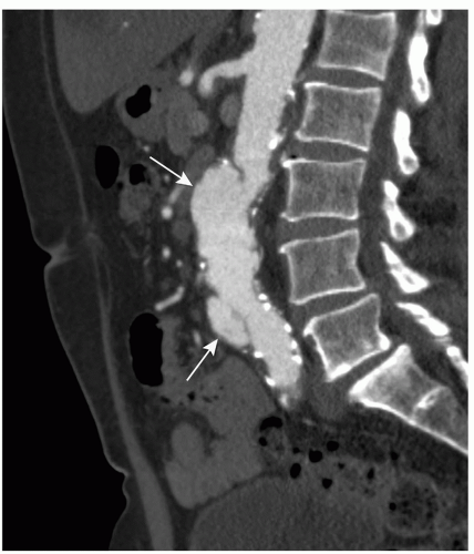 Figure 34.2. Multiplanar reformation (MPR) presentation in the mid-sagittal pane. Patient with an AAA and penetrating ulcers anteriorly (arrow). The focus of interest (penetrating ulcer) is clearly depicted with this MPR technique, although the larger part of the aorta is not visualized in this plane. |
For the renal arteries slice thickness is 0.5 mm, helical pitch is 53, and reconstruction index and interval are 1 and 0.8 mm, respectively. Tube current modulation is used resulting in different milliampere per patient; kV (120), and rotation time (500 milliseconds) is unchanged. Parameters can be changed individually depending on the patient’s weight.
Standard vascular protocols for the Aquilion 320 (Toshiba Medical Systems) routinely use a slice thickness of 0.5 mm. Helical pitch is 65, and reconstruction index and interval are 1 and 0.8 mm, respectively.
POSTPROCESSING
A great challenge of MDCT is in dealing with a large data load (13), especially if an isotropic or near isotropic acquisition is performed (3). For example, routine multislice CTA of the abdominal aorta with a scan range of 30 cm performed with 1-mm collimation and a reconstruction index of 1 mm and reconstruction interval of 0.8 mm produces 375 images. Using 64-slice CT scanners, collimations of 0.5 mm can be achieved and thus a reconstruction index of 0.5 and a reconstruction interval of 0.4 can be used. Using these parameters, 750 images are generated for the same scan volume. However, in our opinion, using slice thickness of 0.5 does not substantially add to the diagnosis in abdominal CTA and we therefore use a reconstruction index and interval of 1 and 0.8 mm as indicated earlier in 64- and 320-slice CT. Imaging the peripheral arteries generates even more images, because the scan volume is much larger. Workstation-based review is necessary not only to evaluate the axial images, which still remains the primary mode for evaluating the abdominal aorta (14), but also to generate reconstructed and 3D images (13). Several reconstruction techniques can be used, which allows better evaluation of the entire vasculature. The main visualization techniques are multiplanar reformation (MPR), maximum intensity projection (MIP), and volume rendering (VR) (15).
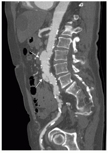 Figure 34.3. Same patient as in Figure 35.2. CPR presentation in the sagittal plane through the aorta and right iliac artery. CPR presentation allows better evaluation of the vascular system through the entire dataset, especially with tortuous atherosclerotic arteries. Penetrating ulcer (arrow). |
An MPR is a 2D reconstruction in any coronal, sagittal, or oblique plane. MPR presentation is easy to use, but restricted to a single 2D plane. Therefore it is of limited value for vascular imaging, especially in tortuous arteries (Fig. 34.2). A more sophisticated technique is curved planar reformation (CPR). With CPR reformation, the display planes curve along an anatomic structure through the entire dataset (16), for example, the abdominal aorta and a single iliac artery (Fig. 34.3), projected in a 2D image. This technique is a valuable tool for vascular imaging. We use a Vitrea workstation (Vital Images Incorporated, Plymouth, MN), which
can generate CPRs semiautomatically. At the same time, additional perpendicular images are displayed, allowing better evaluation of diameters, stenosis, and thrombus composition, thereby improving visualization of eccentric lesions.
can generate CPRs semiautomatically. At the same time, additional perpendicular images are displayed, allowing better evaluation of diameters, stenosis, and thrombus composition, thereby improving visualization of eccentric lesions.
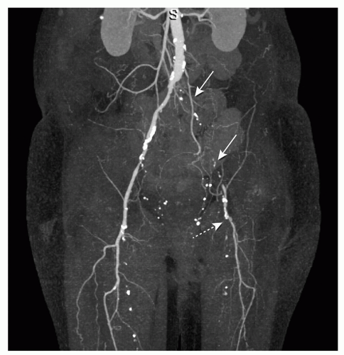 Figure 34.4. Maximum intensity projection (MIP) presentation in the anteroposterior plane in a patient with occlusion the left iliac arteries (arrows) and left superficial femoral artery (dotted arrow). Editing was performed to remove overlying bone. MIP presentation shows an angio-like image. |
MIP presentation visualizes only the brightest structures in a selected plane (e.g., anteroposterior) and provides an angio-like image presentation (Fig. 34.4) (14). Thick- or thinslab MIP images can be obtained. Thin-slab images allow better visualization of complicated anatomic structures. A limitation of the MIP technique, because it is a projection technique, is that more attenuated structures like bones obscure the contrast-enhanced blood vessels (13). Editing to remove overlying structures from the MIP images is usually time consuming. Another limitation of MIP presentation is the absence of the appreciation of depth relationships, especially in regions with a complex anatomy (13). MIP presentations are sometimes inadequate for visualizing small vascular structures, for example, accessory renal arteries in living-related kidney donors. Variants of MIP are minimum intensity projections and curved-slab MIP. The latter can include multiple vessels in a single image with improvement of the interpretation efficiency (17).
VR is the most complex technique (Fig. 34.5). With VR, every voxel value is assigned an opacity level, ranging from opacity to transparency. The opacification function can be applied to a selected region in the histogram of voxel opacity values, thereby visualizing the selected tissue of interest, for example, blood vessels (13). Colors can be applied to the attenuation histogram, to differentiate voxel values and, for instance, to distinguish a calcified plaque from enhancing arterial lumen. VR presentations can be used for virtual endoscopy to evaluate the internal surface of tubular structures (13,18). Mostly basic VR presentations are provided by dedicated post-processing software without prior editing. In addition, smaller regions of interest can be isolated from the scan volume manually by using dedicated software.
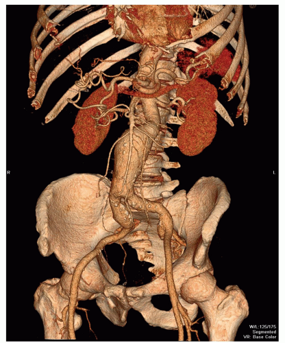 Figure 34.5. Basic volume rendering (VR) presentation of abdominal computed tomographic angiogram (CTA) directly provided by dedicated postprocessing software without editing. Note the infrarenal aortic aneurysm. |
Additional visualization techniques like MIP and VR presentations are most often used in vascular imaging. The interpretation of an examination of the abdominal aorta takes approximately 20 minutes, using a dedicated workstation. Evaluating only 3D images is not an option because of the limitations that have been discussed. It is always important to review the cross-sectional images to obtain additional information (6).
CLINICAL APPLICATIONS
ABDOMINAL AORTA
Abdominal Aortic Aneurysm
Patients with AAA often remain without any symptoms until rupture occurs, with a high mortality rate. AAA occurs most often in middle-aged and elderly patients, and in more men than women with a ratio of 4:1. The pathogenesis of an AAA is complex. Risk factors for atherosclerosis and AAA are overlapping (19).
Aneurysms can be classified according to their cause (20). Most aneurysms are degenerative atherosclerotic aneurysms (Fig. 34.5). Atherosclerotic penetrating ulcers can cause small aneurysms (Figs. 34.2 and 34.3), with a high rupture rate up to 40% (21). Other types of aneurysms are infectious, inflammatory, traumatic, congenital, and postoperative anastomotic aneurysms. It is important to differentiate between these causes, because therapy strategies differ with the cause of the aneurysm. Aneurysms can also be classified according to their anatomic form (saccular, fusiform, true or false aneurysms) or their anatomic location (20). The latter allows classification of AAAs into thoracoabdominal aneurysms, suprarenal aneurysms (involvement of the aorta above the renal arteries), juxtarenal aneurysms (involvement of the aorta at the level of the lowest renal artery or within 5-mm distance from the lowest main renal artery), and infrarenal aneurysms (with a neck of normal aorta between the renal arteries and the beginning of the aneurysm).
The most important issue in evaluation of AAA is accurate diameter measurement, because the maximum diameter of the aneurysm is an important predictor for rupture. Aneurysms exceeding 5 cm in diameter have a higher rupture rate (22,23), whereas the risk of rupture of small (<5 cm) AAA is quite low. Surveillance of AAA up to a diameter of 5.5 cm has been considered safe, unless rapid expansion (>1 cm/y) or symptoms develop (24,25). In addition, there is some uncertainty about the management of relatively small aneurysms in females where aneurysm repair should be considered at a maximum aneurysm diameter of 5.2 cm (25). Expansion rates of aneurysms are variable. Follow-up examinations are important for monitoring the expansion rate (23). Diameter measurements are usually larger with CT than with ultrasound (US) (26). With standardized measurements on CT or US in routine follow-up, changes in diameter can be detected easily. However, reliable information for optimal planning of endovascular intervention or surgery cannot be obtained by US alone.
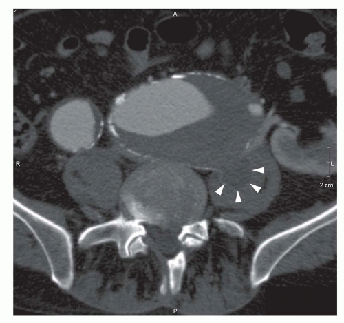 Figure 34.6. Axial computed tomography (CT) image in a patient with an abdominal aneurysm with extension in both iliac arteries. Image is taken at the level of the common iliac arteries. Contained rupture of the left iliac aneurysm (arrowheads) with extension in the left psoas muscle. |
It has been demonstrated that the maximum diameter of the aneurysm is not enough for estimation of rupture risk, because small aneurysms may also rupture (27,28). Peak wall stress distribution, which can be measured from the CT data in combination with patient-related factors such as blood pressure, seems to be superior for predicting rupture risk compared with maximal aneurysm diameter measurements (29). Measuring peak wall stress might affect therapy strategy for small aneurysms with high wall stress and large aneurysms with low wall stress in patients at high risk for surgery (30). Although research on aneurysm rupture and peak wall stress has been ongoing in the past years, the value of peak wall stress distribution for use in the routine clinical practice has not yet been established.
Contained rupture may be observed in patients presenting with an acute symptomatic AAA if their condition allows CT imaging (Fig. 34.6). CT imaging may show a large retroperitoneal hematoma, and sometimes the location of rupture (Fig. 34.7).
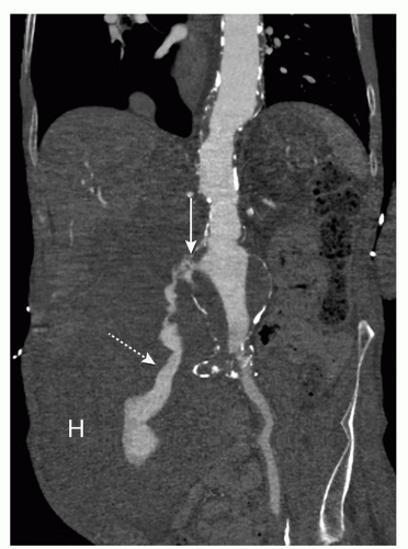 Figure 34.7. Curved multiplanar reformation (MPR) of an acute ruptured AAA. The site of aortic rupture is on the right (arrow) with active bleeding (dotted arrow) and a large retroperitoneal hematoma (H). |
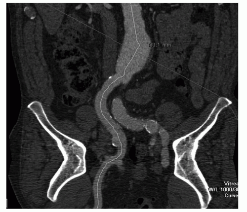 Figure 34.8. CPR presentation through the aorta and right iliac artery in a patient with an AAA. The line is perpendicular to the aortic lumen. The distance displayed (80.1 mm) represents the distance between the level of the lowest renal artery (small line at the top) and the largest aneurysm diameter. Diameter and length measurements for stent grafts are easy to perform with CPR presentations. |
Exact evaluation of large aneurysms (>5 cm in diameter) is important for clinical decision making and planning therapy, and should provide all anatomic information necessary for planning surgery or endovascular aneurysm repair (EVAR) (31).
Evaluation of aneurysms should include the location, length, and diameter of the aneurysm, the extension proximal and distal, the status of the neck of the aneurysm, and the diameter and length of the iliac arteries, and iliac aneurysms, when present (32). Abnormalities of renal, visceral, iliac, and femoral arteries, the number and size of the accessory renal arteries and anatomic variants, and vessel configuration must also be evaluated (19,32). Furthermore, the cause of the aneurysm should be sought (20). Previous techniques requiring both calibrated angiography and singleslice CT, were invasive and did not visualize mural thrombus and the diameter of neck of the aneurysm and iliac arteries adequately. The use of MDCT with 3D reconstructions allows all the information needed, thus eliminating x-ray angiography as a preoperative examination method (33,34 and 35) (Fig. 34.8).
Unenhanced CT in the evaluation of AAA before EVAR allows evaluation of calcifications. Contrast-enhanced CTA is required for evaluating anatomic information and performing measurements, necessary for stent-graft selection.
Endovascular Aortic Aneurysm Repair and Endoleak
Since it was first used in the early 1990s (36), EVAR has become increasingly accepted for treatment of infrarenal AAA. The stent graft, composed of a wired metal frame and prosthetic graft material, is inserted through the femoral arteries and excludes the aneurysm from the circulation, thereby preventing aneurysm rupture (32).
Randomized trials comparing conventional and endovascular repair concluded that peri-operative mortality and complications (the first 30 days after a procedure) were lower with endovascular repair of AAA (37,38 and 39). However, in recently published data, endovascular and open repair of AAA resulted in similar rates of 6-year survival (40). In addition, the rate of secondary interventions was significantly higher for endovascular repair (40). Therefore, the choice between endovascular and open repair will mainly rely on the preference of both patient and doctor and on aneurysm anatomy.
Successful EVAR relies on accurate preoperative AAA imaging for patient selection (34). Detailed measurements must be obtained, because endovascular stent-graft types and sizes are selected per patient and based on these measurements. A small error in stent-graft size can lead to major problems such as endoleak, stent migration, or other complications resulting in stent failure, the need for conversion to open repair, or even aneurysm rupture (33).
Most limitations for endovascular treatment of abdominal aneurysms are related to proximal neck anatomy of the aneurysm (41,42 and 43). Evaluation of the neck requires measurement of the neck length, tapering, degree of angulation, and evaluation of presence of mural thrombus. The length of the neck is the distance between the most caudal renal artery and the beginning of the aneurysm. When the neck length is shorter than 15 mm, sealing problems are likely to occur (44). Fenestrated stent grafts or stent grafts with suprarenal fixation can be used to solve this problem (45). Proximal fixation problems of the stent graft can occur when more than a 2-mm reverse taper is present in the neck of the aneurysm within the first centimeter below the renal arteries (41). Angulation of the neck is defined as the angle between the longitudinal axis of the proximal aortic neck and the longitudinal axis of the aneurysm (Fig. 34.9). Increased risk for complications occurs with moderate (40 to 59 degrees) or severe (>59 degrees) angulation of the neck, compared with mild (<40 degrees) angulation, even if the neck length is more than 2 cm (46


Stay updated, free articles. Join our Telegram channel
Full access? Get Clinical Tree
