Comprehensive and Abbreviated Intraoperative TEE Examination
Jack S. Shanewise
Daniel P. Vezina
Michael K. Cahalan
Since its first use assessing cardiac function in the operating room over 20 years ago (1,2,3), transesophageal echocardiography (TEE) has come to play a critical role in the anesthetic management of patients undergoing surgery that involves the heart and great vessels. It is used as a diagnostic tool during cardiac surgery as well as a monitor of cardiac function, and many studies have shown that it has a significant impact on both the surgical care and anesthetic management these patients receive (4,5,6,7). This chapter will review an approach to performing a comprehensive intraoperative TEE examination using a multiplane probe.
There are several good reasons to complete a comprehensive TEE examination whenever possible. One important aspect of learning TEE is to become familiar with normal and abnormal anatomy of the heart and great vessels as imaged with echocardiography. The more complete exams performed, the more exposure there is to normal and abnormal pathology. Complete examinations also maximize exposure to the various TEE views, allowing one to become familiar with these more quickly. Performing and recording a comprehensive TEE examination at the beginning of an operation establishes a set of baseline findings. Should unexpected problems arise later in the case, this baseline record can be reviewed to determine whether subsequently noted findings are new or were preexisting. Finally, there is a small but important percentage of patients in which the comprehensive TEE examination reveals an unexpected incidental finding, which often can have an important impact on the care a patient receives. There may be situations in which the patient is unstable and a complete examination cannot be performed; in this situation, the main purpose of the TEE examination should be accomplished first so that the important issue for the case is addressed. Then, the remainder of the comprehensive examination may be completed as the situation allows.
PREVENTION OF TEE COMPLICATIONS
Although generally a very safe procedure when performed in appropriately selected patients with proper technique, TEE can, on rare occasions, result in serious complications (8,9). Therefore, every comprehensive TEE examination begins with a search for contraindications to the procedure (Table 6.1). Symptomatic esophageal stricture, esophageal diverticulum, recent esophageal surgery, and esophageal tumor are generally considered absolute contraindications to TEE. Assessment before the procedure includes a review of the medical record and an interview with the patient whenever possible. Specific questions are asked regarding the presence of dysphagia, hematemesis, and a history of esophageal disease. When a history of esophageal disease or symptoms is discovered, the relative risk of performing TEE must be balanced against the potential benefit of the procedure. The decision to proceed despite such symptoms should be documented in the medical record with an acknowledgement of the increased risk, including informed consent from the patient. Evaluation by a gastroenterologist with
esophagoscopy can be helpful in assessing the risk of performing TEE.
esophagoscopy can be helpful in assessing the risk of performing TEE.
TABLE 6.1. Contraindications for Transesophageal Echocardiography | ||||||||||||||||||||||||
|---|---|---|---|---|---|---|---|---|---|---|---|---|---|---|---|---|---|---|---|---|---|---|---|---|
| ||||||||||||||||||||||||
Excessive force must never be used to insert or manipulate the probe within the esophagus. Perforation of the pharynx by TEE probe insertion and of the esophagus from TEE examination have been reported (10,11) and may be more likely in elderly women, possibly due to more delicate tissue and smaller body size. Less catastrophic complications of TEE include dental and oropharyngeal trauma, mucosal injuries causing GI bleeding, and laryngeal dysfunction, possibly increasing the risk of aspiration postoperatively (12,13). One case report also documented the displacement of an esophageal stethoscope into the stomach occurring during a TEE examination. The dislodged device was retrieved several weeks later using endoscopy (14).
INTRAOPERATIVE TEE INDICATIONS
There are three categories of indications for intraoperative TEE described by the ASA/SCA Practice Guidelines (15). Category one indications are supported with the strongest evidence in the literature and expert opinion and include hemodynamic instability and valve repair surgery. Category two indications are supported by weaker evidence in the literature and expert consensus. These include patients at risk for myocardial ischemia during surgery and operations to remove cardiac tumors. Category three indications have little scientific evidence or expert support for their use and include monitoring for emboli during orthopedic procedures and intraoperative assessment of graft patency. In judging whether intraoperative TEE is indicated in a particular situation, three factors must be considered. First are patient characteristics—specifically the presence and nature of cardiovascular disease and risk factors for TEE. Second, the surgical procedure and the role that TEE could play in facilitating its accomplishment must be considered. Finally, the availability of appropriate echocardiographic equipment and expertise in the institution where the procedure is to be formed must be considered.
OPTIMIZING IMAGE QUALITY
The settings of the echocardiography system have an important impact on the quality of the images obtained. One of the challenges of learning TEE is to know when the image has been optimized, even if of poor quality, and when further efforts to improve it are a waste of time. There is a fair amount of variation in the quality of echo images from patient to patient based on individual variations. The depth of the image is adjusted so that the entire structure of interest is included and centered in the image. General image gain and dynamic range (compression) are adjusted so that the blood in the chambers is nearly black but distinct from the gray scales of the soft tissues. Time gain controls are adjusted so that there is a uniform level of overall brightness from the near field to the far field of the image. Most TEE probes can provide images on several frequencies. Higher frequencies have better resolution but less penetration than lower frequencies, so the highest frequency with adequate penetration to provide a clear image of the structure being examined is selected. Color flow Doppler is adjusted by increasing the gain until background noise appears in the color sector, and then decreasing it just until the noise is no longer visible. The size and position of the color sector are set to be as small as possible still including the entire area of interest. This helps increase the frame rate, or temporal resolution of the image.
COMPREHENSIVE TEE EXAMINATION
The American Society of Echocardiography (ASE) and the Society of Cardiovascular Anesthesiologists (SCA) jointly published guidelines for performing a comprehensive intraoperative TEE examination (16,17). The guidelines describe 20 views of the heart and great vessels that include all four chambers and valves of the heart as well as the thoracic aorta and the pulmonary artery (Fig. 6.1). The order in which these views are acquired during a TEE examination will vary from person to person. The following is a description of an approach to performing a comprehensive intraoperative TEE. It is merely one example of many equally valid ways to proceed. It is usually most efficient to complete all of the midesophageal views first, proceed to the transgastric views, and then finish up with an examination of the thoracic aorta.
General Considerations
The process of examining cardiac structures with TEE begins with moving the transducer into the desired location, and then pointing the imaging plane in the proper direction by manipulating the probe to obtain the desired image. This is accomplished primarily by watching the image develop as the probe is manipulated rather than by relying on the depth markers of the probe or the multiplane angle icon on the screen. These markers and orientation guides can provide a general indication of the transducer location and imaging plane orientation, but final development of the image is always based on the appearance of the structures displayed in the image. There is individual variation in the anatomic relationship of the esophagus to the heart, and this relationship must be taken into consideration when performing a TEE examination. In some patients the esophagus is lateral to the
heart, while in others it is more directly posterior to the left atrium (LA). The up-down and left-right orientation of the TEE image can be adjusted on the machine as desired. Figure 6.2 shows the image orientation recommended in the ASE/SCA guidelines.
heart, while in others it is more directly posterior to the left atrium (LA). The up-down and left-right orientation of the TEE image can be adjusted on the machine as desired. Figure 6.2 shows the image orientation recommended in the ASE/SCA guidelines.
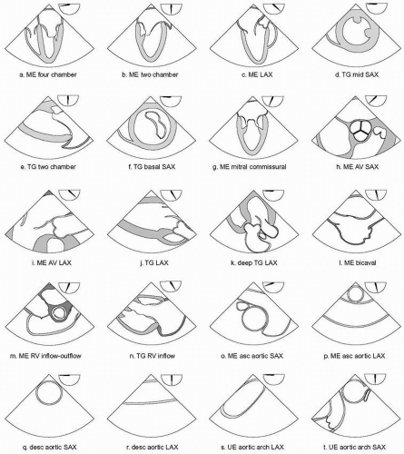 FIGURE 6.1. Twenty cross-sectional views comprising the recommended comprehensive TEE examination. Approximate multiplane angle is indicated by the icon adjacent to each view. ME, midesophageal; TG, transgastric; UE, upper esophageal; SAX, short axis; LAX, long axis; AV, aortic valve; RV, right ventricle; asc, ascending; desc, descending. |
TEE produces a two-dimensional image or cross section through the structure being examined, which exists in three dimensions in space. In order to examine each structure in its entirety it is necessary to move the imaging plane through the three-dimensional extent of the structure by manipulating the probe. This is done for the more horizontal imaging planes (multiplane angles close to zero and 180 degrees) by advancing and withdrawing the probe within the esophagus and for the more vertical imaging planes (multiplane angles close to 90 degrees) by turning the probe to the patient’s left and right. The imaging plane can also be moved through a structure by increasing or decreasing the multiplane angle while holding the probe still with the structure in the centerline of the image. It is best to focus attention on one structure at a time, following the same sequence in each study. The preferred sequence of the examination will vary from person to person, but if followed routinely it will ensure that each structure is checked on each examination. Each structure should be examined with multiple imaging planes and from more than one transducer position if possible.
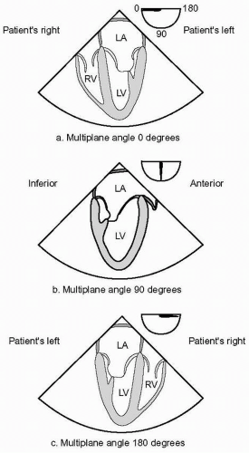 FIGURE 6.2. Conventions of image display followed in the guidelines. Transducer location and the near field (vertex) of the image sector are at the top of the display screen and far field at the bottom. A: Image orientation at multiplane angle zero degrees. B: Image orientation at multiplane angle 90 degrees. C: Image orientation at multiplane angle 180 degrees. LA, left atrium; LV, left ventricle; RV, right ventricle. |
TEE Probe Insertion
The TEE probe is inserted into the esophagus after induction of general anesthesia and tracheal intubation when used during surgery. An orogastric tube is inserted into the stomach prior to inserting the probe and suction applied to remove air or fluid that may be present in the stomach and esophagus. After the orogastric tube is removed, the TEE probe is inserted gently into the midline of the posterior pharynx while the mandible is displaced anteriorly with a jaw lift or thrust in order to lift the tongue and the glottis off the posterior pharynx. Gentle attempts to insert the probe blindly may be tried. However, if after a few attempts the probe does not pass into the esophagus, a laryngoscope is used to displace the mandible anteriorly and provide visualization that the probe is in the midline. Excessive force must never be used, and on rare occasions the TEE probe simply will not pass into the esophagus, and the procedure must be abandoned.
TEE Probe Manipulation
After the TEE probe is inserted, it is manipulated to develop and acquire a series of images of the heart and great vessels. The following terminology is used in the ASE/SCA guidelines to describe the manipulation of the probe (Fig. 6.3). These terms are made assuming that the imaging plane is directed anteriorly from the esophagus through the heart in a patient in the standard supine anatomic position. Rotating the anterior aspect of the probe within the esophagus toward the patient’s right is called “turning to the right,” and rotating it toward the left is called “turning to the left.” Pushing the tip of the probe more distal into the esophagus or the stomach is called “advancing the transducer,” and pulling the tip more proximally is called “withdrawing.” Flexing the tip of the probe with the large control wheel anteriorly is called “anteflexing,” and flexing it posteriorly “retroflexing.” Flexing the tip of the probe with the small control wheel to the patient’s right is called “flexing to the right,”
and flexing it in the opposite direction is called “flexing to the left.” Finally, increasing the transducer multiplane angle from zero degrees towards 180 degrees is called “rotating forward,” and decreasing in the opposite direction towards zero degrees is called “rotating back.”
and flexing it in the opposite direction is called “flexing to the left.” Finally, increasing the transducer multiplane angle from zero degrees towards 180 degrees is called “rotating forward,” and decreasing in the opposite direction towards zero degrees is called “rotating back.”
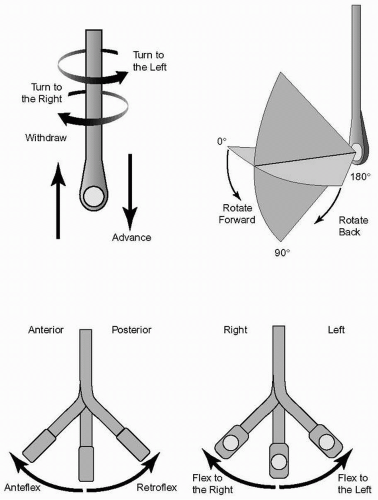 FIGURE 6.3. Terminology used to describe manipulation of the probe and transducer during image acquisition. |
Left Atrium and Pulmonary Veins
The comprehensive TEE examination is started by locating the transducer at the midesophageal level posterior to the LA. The LA is then examined from top to bottom with the multiplane angle at zero degrees (horizontal plane) by advancing the probe until the plane passes through the floor of the LA and then withdrawing until the dome of the atrium is reached. The multiplane angle is then increased to about 90 degrees and the probe turned to the left. Near the lateral and superior aspect of the LA, the base of the left atrial appendage (LAA) is seen opening into the atrium. The LAA is examined carefully for thrombus by increasing and decreasing the multiplane angle while holding the LAA on the centerline of the image. Turning the probe to the left and withdrawing slightly identifies the left upper pulmonary vein (LUPV), which enters the LA from an anterior to posterior direction just lateral to the LAA. Pulsed wave Doppler is used to examine the LUPV flow velocity profile by placing the sample volume at least 1 cm within the vein. Advancing 1 to 2 cm and turning slightly further to the left will identify the left lower pulmonary vein (LLPV). In some patients the LUPV and LLPV enter the LA as a single vessel. Adjusting the multiplane angle up and down will often open up the veins in the image. The right upper pulmonary vein (RUPV) is next examined by turning the probe to the right at the level of the LAA beyond the interatrial septum (IAS). Like the LUPV, the RUPV can be seen to enter the superior aspect of the LA in an anterior to posterior direction. The right lower pulmonary vein (RLPV) is then seen by turning the probe slightly to the right and advancing 1 to 2 cm.
Mitral Valve Midesophageal Views
Attention is now turned to the mitral valve (MV), which is examined with several midesophageal views. The MV apparatus includes the anterior and posterior leaflets, annulus, chordae tendinae, papillary muscles, and LV walls. The two leaflets meet at the anterolateral and posteromedial commissures, each of which is related to a corresponding papillary muscle with a similar name. The posterior leaflet anatomically consists of three scallops: lateral (P1), middle (P2), and medial (P3). For descriptive purposes, the anterior leaflet is divided into thirds: lateral third (A1), middle third (A2), and medial third (A3) (Fig. 6.4).
The first step in developing the midesophageal views of the MV is to position the transducer posterior to the midlevel of the LA and direct the imaging plane through the middle of the mitral annulus parallel to the transmitral flow. Retroflexion of the probe tip is often necessary to achieve this because the MV annulus is located inferior to the base of the heart in many patients. The multiplane angle is then increased just until the aortic valve (AV) disappears to develop the midesophageal four-chamber view (Fig. 6.1a), usually around 10 to 20 degrees. In this view the posterior mitral leaflet is to the right of the image display, and the anterior mitral leaflet is to the left. Because the midesophageal four-chamber view transects the MV obliquely, it is difficult to be sure exactly which portion of the anterior and posterior leaflets are seen in a particular image. A transition in the image occurs as the multiplane angle is increased to about 60 to 80 degrees. Beyond the transition point the anterior leaflet is to the right of the display and the posterior leaflet is to the left. At this transition angle, the imaging plane intersects both commissures of the MV simultaneously, forming the midesophageal mitral commissural view (Fig. 6.1g). In this view the middle third of the anterior leaflet (A2) is seen in the middle between portions of the posterior leaflet on each side; the lateral scallop (P1) to the right of the display, and the medial scallop (P3) to the left. From the midesophageal mitral commissural view turning the probe to the right moves the plane toward the medial or right side of the MV through the base of the anterior leaflet, and turning the probe to the left moves the plane toward the lateral side through the posterior leaflet. Next, the multiplane angle is rotated forward to between 120 to 160 degrees until the left ventricular outflow tract (LVOT), AV, and proximal ascending aorta line up in the image to develop the midesophageal long-axis view (Fig. 6.1c). The midesophageal long-axis view, like the midesophageal mitral commissural view, is oriented to the anatomy of the MV and useful for identifying regions of the leaflets. In this view the anterior mitral leaflet (middle third, A2) is to the right of the display and the posterior mitral leaflet (middle scallop, P2) is to the left. With proper orientation of the imaging plane through the center of the mitral annulus, the entire MV can be examined from the midesophageal window without moving the probe by rotating forward from 0 to 180 degrees. Color flow Doppler is applied to the midesophageal views of the MV to detect flow disturbances such as mitral regurgitation or mitral stenosis. This is easily accomplished by rotating the multiplane angle backwards from the midesophageal long-axis view through the mitral commissural and four-chamber views. The transmitral inflow velocity profile is examined with pulsed wave Doppler in the midesophageal four-chamber view or midesophageal long-axis view by placing the sample volume between the open tips of the mitral leaflets. This is useful for assessing mitral stenosis and diastolic function of the LV.
Stay updated, free articles. Join our Telegram channel

Full access? Get Clinical Tree


