Fig. 3.1
General structure of a CMR pulse sequence. The key components (magnetization preparation, respiratory navigation (NAV) and imaging (readout)) are defined within two consecutive R waves (i.e. within an R-R interval). Magnetization preparation may not be present in pulse sequences that generate image contrast from the imaging (i.e., Readout) block. Similarly, the NAV block is typically not present when imaging is performed with voluntary suspension of breathing. While the typical order of the blocks is as drawn, the duration and exact position of the blocks within the R-R interval can vary greatly between sequences
One of the distinguishing features of CMR acquisitions, compared to imaging other organ systems, is that the acquisitions are typically timed relative to the electrocardiographic (ECG) signal within the nominal period between consecutive R waves referred to as the R-R interval. This permits data acquisition to take place at specific time frames within the cardiac cycle, which allows one to capture cardiac phase-dependent features in an image, as well as minimize imaging artifacts (such as, blurring or flow artifacts) from cardiac motion. For instance, cine acquisitions are captured over multiple frames by limiting the data acquisition period to approximately 50 ms or less depending on heart rate. On the other hand, most other (non-cine) CMR acquisitions take place during quiescent periods (typically, mid diastole), where data can be collected over a relatively long period of time (~200 ms) without motion artifacts.
Another important feature of CMR acquisition is that it must account for respiratory motion, which otherwise can also lead to significant image artifacts. The most common approach used to overcome respiratory motion is voluntary suspension of breathing for 10–15 s (breath-holding). In cases where subjects cannot suspend breathing over the acquisition period, particularly in acquisitions that are in excess of 10–15 s (e.g., 3D imaging), other forms of motion compensation are used. Of these approaches, navigator gating is the most common. Here a quick excitation (<30 ms) is applied in a direction perpendicular to the diaphragm and an echo is acquired, reconstructed, and analyzed to determine diaphragm position to estimate respiratory motion. Following image data acquisition, the data that falls within a pre-determined window of diaphragm motion, typically <5 mm, is accepted and used for reconstructing the CMR image. Naturally this process can reduce the time-efficiency of acquisition, particularly if the subject’s breathing pattern is highly variable, since sufficient data needs to be collected to reconstruct an artifact-free image.
RF excitations can be applied to “bias” the magnetization (signal) to different biophysical environments. These excitations are often referred to as magnetization preparation and typically precede the different imaging schemes. Common magnetization preparation schemes are explored in detail in section “Common types of magnetization preparation”. While magnetization preparation is a common and efficient means of sensitizing the protons to generate a desired image contrast, it is to be noted that it is not always necessary to have a separate magnetization preparation component to generate image contrast. In fact, the desired image contrast may be available through optimal scan parameter selection from sequences in which the magnetization preparation is effectively integrated into the imaging sequence itself. The general classes of imaging sequences will be described in section “General classes of sequences”. In general, the utilization of an isolated magnetization preparation scheme prior to imaging is often based on the need to optimize image contrast (CNR), image quality (SNR, spatial resolution, image artifacts), acquisition speed, and specific-absorption rate (SAR).
Common Types of Magnetization Preparation
In this Section we explore the most commonly used magnetization preparation schemes in CMR. In particular, we will look at T1– and T2-weighted preparations and then consider fat suppression and black-blood preparation.
T1-Weighted Preparations
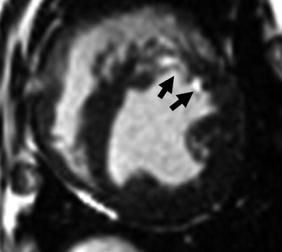
The goal of T1-weighted preparation is to evaluate potential T1 differences within and between tissues; these can be prescribed as an inversion-recovery scheme or saturation recovery scheme. In the inversion-recovery (IR) approach, the equilibrium magnetization (M0) is inverted by a 180° RF pulse which is immediately followed by large gradient pulses designed to spoil any residual transverse magnetization that may have been generated by imperfections in the inversion process. Then, following a waiting period of TI, also referred to as the inversion time, one or more k-space data lines are acquired using any of a variety of sequence types (e.g., spoiled gradient echo, balanced SSFP, or fast spin echo). During TI, the inverted longitudinal magnetization (−M0) recovers towards equilibrium, with the rate of recovery determined by T1. The recovery of the excited spins back to equilibrium will be differentially altered by the T1 distribution in specific tissues. For instance, the T1 of myocardial tissue could be altered by the presence of heterogeneous tissue (healthy myocardium, fat, fibrotic tissue, or elevated free water (edema)), or by the variable distribution of T1-shortening exogenous contrast media. If the TI is selected to coincide with the time that the longitudinal magnetization for tissue of a specific T1 is crossing zero, the tissue is effectively “nulled” and will appear black in the image. This approach is commonly exploited in late-gadolinium-enhanced (LGE) CMR to visualize and quantify infarcted myocardium by selectively nulling the non-infarcted myocardium (Fig. 3.2). This is possible because the infarcted myocardium tends to have a greater concentration of contrast agent (due to reduced contrast Clarance), and therefore a shorter T1, than viable tissue.


Fig. 3.2
Application of inversion-recovery preparation for imaging infarcted myocardium. Late gadolinium enhanced image obtained with IR-preparation with balanced steady-state free precession readout at TI of 330 ms is shown. The IR-preparation “nulls” the healthy myocardium while ensuring the infarcted myocardium (i.e., regions with higher concentration of T1-shortening agent (such as gadolinium chelate) indicated by arrows) appears bright
In the saturation recovery (SR) preparation, the equilibrium longitudinal magnetization is completely tipped into the transverse plane by a 90° RF pulse and is dephased (disordered) in the transverse plane by a magnetic field gradient (“spoiler” or “crusher” gradient) to annihilate the transverse magnetization. After a time delay of TI (in this case, a “saturation delay” although it is still often denoted as “TI”), one or more lines of k-space data are acquired. During TI, the magnetization recovers toward the equilibrium at a rate dependent on T1.
While both IR and SR preparations can be used to generate T1 image contrast, there are some practical differences. In general, IR preparations provide nearly a twofold greater image contrast between tissues of different T1 since the signal recovery following IR preparation spans the full range of −M0 to +M0, whereas following SR preparation the signal varies only over the range of zero to +M0. A key difference between the two preparations is that the signal following an IR prep is dependent on the pre-existing longitudinal magnetization; that is, if the magnetization has not fully recovered from the last preparation or excitation pulses, this will affect the magnitude of longitudinal magnetization that is inverted, and thereby the inversion recovery signal trajectory. On the other hand, the SR prep destroys any existing longitudinal magnetization and starts the recovery from zero regardless of the past history of the magnetization. Because there is no need to wait for recovery of longitudinal magnetization, the recovery period between consecutive SR preparation modules can be kept relatively short, and SR-prepared acquisitions therefore tend be faster as compared to IR-prepared acquisitions. Nonetheless, both methods can be used to generate a pixelwise map of the T1 of the myocardium and other tissues in a process known as “T1-mapping.” This is typically accomplished by acquiring images across a range of TI times and then fitting the signal from each voxel to a mono-exponential equation, the time constant of which is T1.
T2-Weighted Preparations
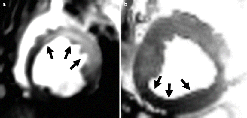
T2-weighted preparations are used to enhance the differences within myocardium that emerge from localized changes in free-water content (edema), blood oxygenation, or intra-myocardial hemorrhage, among other factors. One of the most commonly used T2-weighted preparation schemes involves a composite set of RF pulses that are non-selective (i.e., all spins within the volume of the RF transmitter coil are excited by each of the RF pulses). This scheme, commonly referred to as T 2 preparation, involves the formation of one or more spin echoes and is designed to impart T2 weighting on the longitudinal magnetization. It can be described as follows: first the longitudinal magnetization is tipped into the transverse plane with a 90° RF pulse and then allowed to evolve in the transverse plane for a time, τ. During this period, the magnetization dephases at a rate dependent on the T2 * of the tissue (i.e., with some spins precessing faster than others due to static local differences in magnetic field, as well as due to random spin-spin interactions). At time τ, a 180° pulse is applied which flips the transverse plane and effectively reverses the direction of phase evolution, leading to a coherent signal (echo) at time 2τ after the initial 90° RF pulse (which is also a time of τ after the 180° RF pulse). This echo is referred to as a spin echo and will be described in greater detail in section “Spin-echo sequences”. Subsequently, the magnetization, now weighted by T2 decay rather than T2*, is rotated back to the longitudinal axis and any remaining transverse magnetization is spoiled before imaging. In practice, additional 180° pulses are typically incorporated to minimize refocusing errors due to blood flow and inhomogeneities in the B0 and B1 fields. The total duration between the first and second 90° RF pulses is referred to as the T 2 -preparation period, or T2-prep time. The longer the T2-prep time, the greater is the contrast between regions of myocardium with different T2 values. In practice, the longest practical T2-prep time is typically under 60 ms at 1.5T, and shorter at 3.0T (<50 ms); beyond these times the overall signal loss due to T2 decay can significantly degrade image quality. Among the variety of applications, T2 preparation has been used to examine myocardial edema in acute myocardial infarction (Fig. 3.3a) and changes in myocardial blood oxygenation in the setting of coronary narrowing without exogenous contrast agents (Fig. 3.3b). Using this approach iteratively (i.e., by acquiring a series of images with different T2-prep times) it is possible to generate a T2 map of the myocardium. Fitting the signal intensities of the individual voxels at different T2-prep times to a mono-exponential decay curve, the time constant of which is T2, permits one to generate a T2 map, i.e., an image in which the pixel values are equal to T2.


Fig. 3.3
Application of T2-preparation for imaging myocardial edema (a) and oxygenation (b). (a) T2-preparation is used to highlight the myocardial territory with increased T2 (arrows) due to edema from acute myocardial infarction. (b) T2-preparation is used to highlight the absence of increase in T2 (blood oxygenation) during adenosine infusion from myocardial territories subtended by a stenotic epicardial coronary artery relative to healthy myocardium
Fat Suppression
At times, signal from adipose tissue can confound image interpretation. To minimize this, it is often desirable to suppress adipose tissue, for example, to enable accurate visualization of coronary arteries or characterize myocardial tissue. For instance in post-contrast T1-weighted images, epicardial fat can appear bright which can confound the visualization of infarcted myocardium, especially when the infarction is transmural. In this scenario, suppressing the fat signal could reduce ambiguity regarding the presence and extent of infarcted myocardium. In other situations it may be useful to acquire images with and without fat suppression to aid in determination of whether a particular lesion is comprised of fat. Fat suppression, i.e., reducing or eliminating the signal from fat, may be performed in a number of different ways with each method carrying with it advantages and disadvantages. In this Section we will describe two of the most commonly used preparations, namely, frequency-selective (FS) fat saturation, and short TI inversion recovery (STIR) preparation.
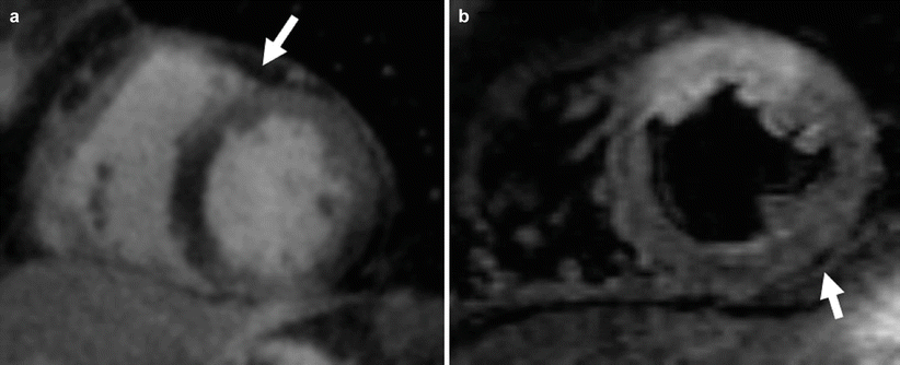
The FS preparation exploits the frequency difference between fat and water protons (−220 Hz at 1.5T and −440 Hz at 3T) to saturate the fat signal. Here an RF pulse with a resonance frequency centered on that of fat is used to saturate the signal from fat. That is, in similar fashion to SR described in section “T1-weighted preparations”, a 90° RF pulse is used to selectively tip the magnetization of lipid protons into the transverse plane, followed by a spoiler gradient to dephase the transverse magnetization. The advantage of this method is that it is frequency selective and therefore only affects the lipid protons resonating at their unique frequency, while not affecting water protons. Thus, FS preparation is a good method for suppressing fat signals when T1 shortening contrast agents are used, since the T1 of fat (200–300 ms) and that of regions with high concentration of gadolinium (e.g., infarcted myocardium) can be similar. However, good suppression of fat signal with this technique requires fairly homogeneous B0 field. If significant field inhomogeneities exist, frequency-selective saturation may not be effective since the RF pulse will only partially saturate the fat, or in the worst case may saturate the water protons instead; this leads to an overall reduction in SNR. Unfortunately, significant B0 field inhomogeneities in and around the heart are not uncommon, especially at 3.0T, due to the large susceptibility gradients that exists at the heart-lung interface, or due to the presence of sternal wires, stents, or other metallic implants that have very different magnetic susceptibility from that of the heart. An example of FS applied to late-gadolinium imaging is shown in Fig. 3.4a.


Fig. 3.4
Suppressing fat with frequency-selective preparation (a) and STIR preparation (b) at 1.5T. (a) Frequency-selective preparation is used to suppress the signal from epicardial fat (white arrow) as part of a coronary artery imaging protocol. (b) Selective nulling of signal from fat protons using the STIR preparation with a TI = 170 ms. Note the suppression of epicardial fat relative to the myocardium (arrow)
Another approach to fat suppression is the Short-Tau Inversion Recovery, or STIR preparation, which exploits the difference in T1 between fat and water-based tissues to suppress the fat signal. Here, a 180° IR preparation (as in section “T1-weighted preparations”) is used to invert the magnetization of both fat and water, using a short TI (approximately 150 ms at 1.5T) specifically chosen to null the fat signal. By acquiring image data near the null point of fat, an appreciable signal from the protons in water-based tissues is realized while the signal from fat protons is effectively reduced to zero. The STIR preparation is not as dependent as FS on B0 homogeneity, and is therefore the preferred method when field inhomogeneities are a problem. Because tissues with long T1 tend to also have long T2, e.g., edematous myocardium, the STIR preparation also effectively enhances T2 contrast by suppressing tissues with shorter T1; hence the STIR technique has been useful for myocardial edema imaging. However, since the STIR preparation will reduce signal from any tissue with shorter T1, including water-based tissues, it can limit overall image SNR. Another disadvantage of this method is that it is generally ineffective following contrast injection, since the post-contrast T1 of water-based tissues may become similar to fat. An example of STIR preparation for myocardial edema imaging is shown in Fig. 3.4b.
Black-Blood Preparation
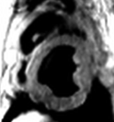
In this preparation, the signal from flowing blood is nulled by a unique inversion recovery strategy, and hence blood appears dark. This is accomplished using a so-called “double IR” strategy in which a non-selective 180° inversion pulse is immediately followed by a slice-selective 180° RF inversion pulse that effectively rotates the spins within the image slice back up to the equilibrium position, i.e., +M0, leaving all of the magnetization outside the slice inverted at −M0. More specifically, (a) the first inversion pulse inverts all the spins within the body coil since it is non-selective; (b) the second slice-selective inversion pulse affects only those spins within the slice of interest, effectively rotating those spins back up to the equilibrium position, i.e., +M0, leaving all of the magnetization outside the slice inverted at −M0; and (c) a long TI period precedes image data acquisition to ensure that inverted blood has time to flow into the imaging slice, and that data are collected when the signal of inflowing blood is at its null point following the first (non-selective) inversion pulse. Commencement of imaging at this point will ensure that moving blood appears “black” while other structures that remained within the imaged slice have signal. An example of a black-blood prepared image is shown in Fig. 3.5. This approach can be combined with other preparation modules, such as STIR, to additionally suppress fat. In general, black-blood preparation is commonly employed to preferentially visualize the blood vessel walls, cardiac chambers, and the myocardium without any contribution from blood. While the advantages of black-blood preparation are widely recognized for visualizing anatomical structures, there are some limitations, foremost of which is the requirement that the blood flow is sufficiently fast so that inverted blood moves into the slice of interest before the start of imaging. In black-blood prepared images, slow moving or stagnant blood can have high signal and may artifactually appear to be an extension of anatomical structures. Rapidly moving myocardium can also be problematic, as inverted myocardium may enter the imaged slice causing an artifactual reduction in myocardial signal.


Fig. 3.5
Application of black-blood preparation for anatomic imaging. Short-axis image obtained with dark-blood prepared gradient-echo acquisition is shown. Note that the cardiac chambers (RV and LV) containing blood appear black due to selective nulling of moving blood, which otherwise would appear bright (refer to Fig. 3.3)
General Classes of Sequences
In this Section, we will examine imaging pulse sequences that are commonly used in CMR as the “Readout” block illustrated in Fig. 3.1. First, we will review the basic structure of imaging sequences and key parameters in section “Basic structure of imaging pulse sequences”. Next, in section “Gradient echo sequences”, we will describe gradient-recalled echo (GRE) sequences starting with the basic gradient echo sequence, extending to the multi-gradient echo (mGRE) sequence, and concluding with the fast incoherent steady-state imaging sequence, also referred to as spoiled gradient echo. In section “Spin echo sequences”, we will review spin echo sequences, beginning with the simple spin echo (SE) sequence followed by the fast spin-echo (FSE) sequence. Finally, in section “Balanced steady-state free precession”, we will review the coherent steady-state sequence, referred to as balanced steady-state free precession (bSSFP).
Basic Structure of Imaging Pulse Sequences
CMR data acquisition for 2D or 3D imaging involves RF excitation of a prescribed slice or slab that includes the region or tissue of interest. In response to RF excitation, all of the tissue inside the excited slice/slab emits a signal referred to as an “echo.” Spatial localization of the echo signal is achieved using magnetic field gradients, which encode the spatial information into the phase and frequency of the echo signal. In general, acquisition of an MR image requires a series of RF and gradient pulses in combination with data acquisition periods that are synchronized to the timing of the echo signals; this is collectively referred to as a pulse sequence. It is often designed to provide the specific image contrast needed for a particular CMR application. For instance, the pulse sequence applied for edema imaging (Fig. 3.3a) is very different from the pulse sequence used to assess myocardial perfusion (described later in Fig. 3.9). The most commonly used CMR pulse sequences can be categorized as “gradient echo” and “spin echo”. Gradient echo sequences employ magnetic field gradients to produce an echo, whereas spin echo sequences use RF pulses to produce an echo.
< div class='tao-gold-member'>
Only gold members can continue reading. Log In or Register to continue
Stay updated, free articles. Join our Telegram channel

Full access? Get Clinical Tree


