Fig. 20.1
Three-dimensional orientation icon displayed in the figures. Abbreviations for orientation markers used in the figures throughout this chapter: A anterior, I inferior, L left, P posterior, R right, S superior
Defining Three-Dimensional Cardiac Anatomy
The ability of 3D echocardiography to demonstrate surfaces, volumes, and spatial relationships allows the echocardiographer to acquire and display views of the heart and great vessels that are analogous to viewing a cardiac pathology specimen [13–24]. Valve leaflets, septal structures, and the real time depiction of spatial relationships provide clearer anatomic definition and better understanding of the actual cardiac anatomy as compared to Two-dimensional (2D) echocardiography [25–27].
Case Examples
Congenitally Corrected Transposition (L-Transposition of the Great Arteries)
Figure 20.2 was obtained from a patient with congenitally corrected transposition, illustrating the four cardiac chambers and valves, imaged from the mid esophageal four chamber (ME 4 Ch) view. These images were obtained using a full volume 3D acquisition mode. This 3D echocardiographic modality is most useful for obtaining the entire cardiac echocardiographic (echo) volume in one cine loop. Once acquired, this echo volume can be cropped and rotated from any or all directions in order to display the relevant anatomy. As this 3D echo modality can be prone to stitch artifact (refer to Chap. 19), breath holding, maximizing 3D echo volume rate, using multiplanar reconstruction mode (MPR), and editing out cine loops in which artifact is present, are important skills to master. Figure 20.2a is cropped with one touch by using the auto crop button, which removes the anterior 50 % of the echo volume. Figure 20.2b is not cropped at all, but is merely a full volume acquisition with the superior plane tilted towards the viewer. Relatively low gain and compression settings, as well as slight angulation or tilting of the 3D cardiac image, should be used in order to enhance the depth shading. Figure 20.3 is a deep transgastric sagittal (DTG Sagittal) view obtained from the same patient with inverted ventricles shown in Fig. 20.2 depicting the three leaflets of the tricuspid valve in the morphologic right ventricle. This image was obtained using the live 3D mode, which maximizes volume rate at the expense of requiring a smaller 3D echo sample volume. This modality has an additional advantage of minimizing stitch artifact and is therefore quite useful for patients with faster heart rates or for viewing rapidly moving structures such as semilunar valves. Especially when learning 3D echo, as well as in cases in which imaging time is limited, such as during surgery and interventional catheterization procedures, we have found it most effective to have two echocardiographers involved: one manipulates the transducer while the other operates the controls on the echocardiography machine. Both roles must be learned and coordinated by both operators in order to achieve the full potential of 3D TEE.
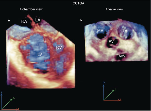
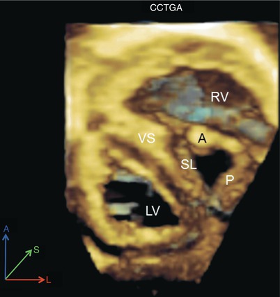

Fig. 20.2
Full volume 3D acquisitions of congenitally corrected transposition (CCTGA). (a) Mid esophageal four chamber view. (b) Four valve upper esophageal view. AoV aortic valve, LA left atrium, LV left ventricle, MV mitral valve, PV pulmonary valve, RA right atrium, RV right ventricle, TV tricuspid valve

Fig. 20.3
Live 3D deep transgastric sagittal axis view obtained in the same patient presented in Fig. 20.2 with congenitally corrected transposition (CCTGA). Note the en face view of the tricuspid valve in the left-sided, anteriorly positioned right ventricle (RV). A anterior leaflet of tricuspid valve, LV left ventricle, P posterior leaflet of tricuspid valve, SL septal leaflet of the tricuspid valve, VS ventricular septum
Cor Triatriatum
Images from a patient with dextrocardia, multiple ventricular septal defects (VSDs) and cor triatriatum undergoing surgical resection of the obstructive membrane are shown in Fig. 20.4. Note the clearly defined anatomic details including the depth, orifices, and surfaces of the cardiac structures in this complex lesion. Also note that, as in the prior case example, we applied 3D full volume to obtain the entire cardiac 3D volume as a first step as illustrated in Fig. 20.4a and Video 20.1. Subsequently we used live 3D to focus on specific details in real time as seen in Fig. 20.4b. The actual obstructive orifice of the cor triatriatum membrane is seen in this figure as if one were viewing a pathology specimen from above. In Fig. 20.5a we applied X–plane color Doppler flow mapping consisting of live biplane echocardiography, analogous to biplane angiography, which provides simultaneous live imaging of the frontal and lateral planes. Using any of the 3D echo modalities one can rotate the cardiac images 180° in order to provide unique views of the heart from its posterior aspect. This is depicted in the 3D color Doppler flow map in Fig. 20.5b and Video 20.2, demonstrating flow through the obstructive membrane orifice in this case.
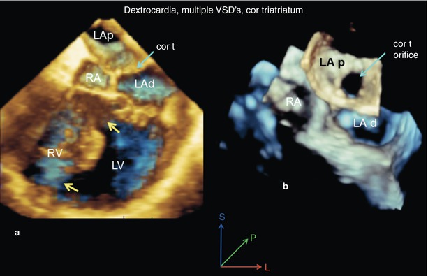
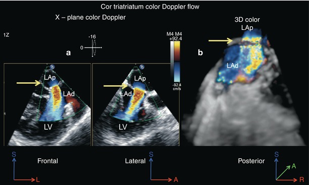

Fig. 20.4
A case of cor triatriatum, dextrocardia and multiple ventricular septal defects (yellow arrows) as seen from the mid esophageal four chamber view, using full volume 3D acquisition. (a) The cor triatriatum membrane (cor t; green arrow) divides the left atrium into proximal (LAp) and distal (LAd) chambers. (b) The image has been cropped from above and tilted forward to demonstrate the cor triatriatum orifice. LV left ventricle, RA right atrium, RV right ventricle

Fig. 20.5
Color Doppler flow analysis is presented from the same case shown in Fig. 20.4. (a) X-plane color Doppler display of the turbulent flow through the cor triatriatum orifice as seen from orthogonal views (frontal and lateral). The cor triatriatum membrane is indicated by the arrow. (b) 3D color Doppler flow map as seen from a posterior view is shown. LAp proximal chamber, LAd distal chamber, LV left ventricle
Bicuspid Aortic Valve
Live 3D images of the two most common types of bicuspid aortic valve, namely left–right commissural fusion and right non-coronary commissure fusion, are presented in Fig. 20.6. The valve leaflet surface and depth can be clearly displayed by 3D imaging (Fig. 20.6, Videos 20.3 and 20.4). The blue depth shading provided by using the H tissue algorithm (3D tissue display), along with lower gain settings, are essential to provide the optimal 3D effect. Also, the anatomic details of leaflet thickening, raphe thickness and orientation, and the valve orifice shape, size, and location are viewed in greater detail. We consider live 3D acquired from the mid esophageal aortic valve short axis (ME AV SAX) view to be the best currently available modality to obtain these anatomic details of the aortic valve.
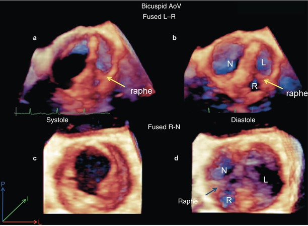

Fig. 20.6
Live 3D mid esophageal aortic valve short axis acquisitions of the two most common variants of the bicuspid aortic valve. Images in the top row are from a patient with left and right leaflet fusion (fused L-R). The view during systole is labeled (a) and the view during diastole is labeled (b). Images in the bottom row are from a patient with right and non-coronary leaflet fusion (fused R-N). The view during systole is labeled (c) and the view during diastole is labeled (d)
Parachute Mitral Valve
Parachute mitral valve deformities from two patients are presented on Figs. 20.7 and 20.8 respectively. Figure. 20.7a is a 3D zoom acquisition of the mitral valve in which the hypoplastic mitral valve orifice is viewed from the left atrium. 3D zoom mode is our preferred method to visualize the mitral valve because it is live, rapid and very easy to perform. It has the drawback of having a slow volume rate, although this problem can be mitigated by using the high volume rate (HVR) imaging modality. This modality is chosen on the control knobs of the echocardiographic platform. It provides for increased volume rate at the expense of slightly decreased resolution and limited quantitative capabilities. Figure 20.7b and Video 20.5 are from a frontal cropped 3D full volume of the hypoplastic stenotic parachute mitral valve, obtained from the ME 4 Ch view. Live 3D was used to acquire Fig. 20.8, which demonstrates a parachute mitral valve in a patient with double inlet left ventricle. Note from these three examples that after the image has been acquired and appropriately cropped and displayed, it is not always easy to determine which acquisition modality—3D zoom vs. full volume 3D vs. live 3D—was employed.
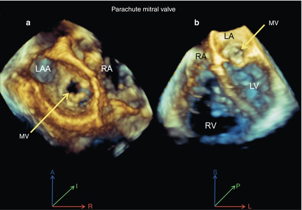
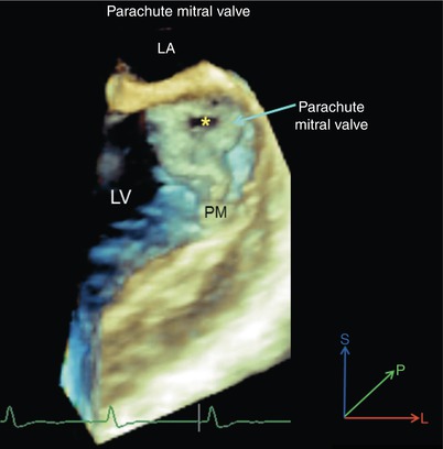

Fig. 20.7
Views of a parachute mitral valve. (a) 3D zoom mode acquisition viewed from the left atrium shows the hypoplastic mitral valve (MV) orifice (yellow arrow). (b) Full volume 3D mid esophageal four chamber view displays the hypoplastic and doming mitral valve (yellow arrow). LA left atrium, LAA left atrial appendage, LV left ventricle, RA right atrium, RV right ventricle

Fig. 20.8
Live 3D acquisition in a patient with double inlet left ventricle and parachute left sided atrioventricular valve obtained from the mid esophageal four chamber view. The very small mitral orifice , single small papillary muscle (PM) and parachute or funnel shape deformity of the mitral valve are apparent. LA left atrium, LV left ventricle
Ventricular Septal Defects
The advantages of 3D TEE to demonstrate the anatomy of VSDs are apparent in Figs. 20.9 and 20.10. En face views of the ventricular septum from either the right or left ventricular aspect demonstrate the size, shape, location, and orientation of the defect as well as its relationship to surrounding structures. An interesting aspect of VSD imaging we have noted is that the majority of defects we have examined have the longest dimension in the Z plane (anterior-posterior), a plane unique to 3D echocardiography. Therefore the actual largest dimension and overall size of the VSD may be better depicted using 3D versus 2D echocardiography in many cases. Figure 20.9 represents live 3D color Doppler flow maps of a muscular VSD from a slightly oblique ME 4 Ch view (Fig. 20.9a) and a mid esophageal long axis (ME LAX) view (Fig. 20.9b, Video 20.6). The images in Fig. 20.10 are cropped full volume 3D acquisitions of a perimembranous VSD. The right (Fig. 20.10a) and left ventricular en face views (Fig. 20.10c) are obtained by cropping from the respective right or left sides and rotating the images to face the viewer. Obtaining en face views of septal structures is one of the basic 3D echo skills that must be mastered in the assessment of congenital heart defects. The center Fig. 20.10b and Video 20.7 are the frontal cropped full volume images obtained from the ME 4 Ch view, as previously discussed.
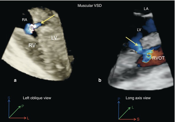
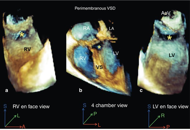

Fig. 20.9
Live 3D color Doppler flow mapping images of a muscular ventricular septal defect (VSD). (a) Mid esophageal four chamber view showing the VSD with a left oblique rotation. (b) Demonstration of the defect using a mid esophageal long axis view, the left to right shunt is indicated by the arrow

Fig. 20.10
A perimembranous ventricular septal defect (VSD; asterisk) as seen from a mid esophageal four chamber view using full volume 3D acquisition. (a) Right-sided en face view. (b) Four chamber view with slight rightward probe rotation. (c) Left-sided en face view. AoV aortic valve, LA left atrium, LV left ventricle, RA right atrium, RV right ventricle, VS ventricular septum
Double Inlet Left Ventricle
Images from a patient with double inlet left ventricle, acquired from the ME 4 Ch view using full volume 3D TEE are presented in Fig. 20.11. By cropping the image from the superior direction and tilting the cardiac base toward the viewer, the atrioventricular (AV) valves are seen from the atrial view (Fig. 20.11a). By cropping from the inferior direction and tilting the apex toward the viewer, the AV valves are seen from the ventricular view (Fig. 20.11b). Finally, another example of a frontal cropped ME 4 Ch view is demonstrated (Fig. 20.11c). This view functions as a good home base view from which to proceed with more involved 3D cropping and views.
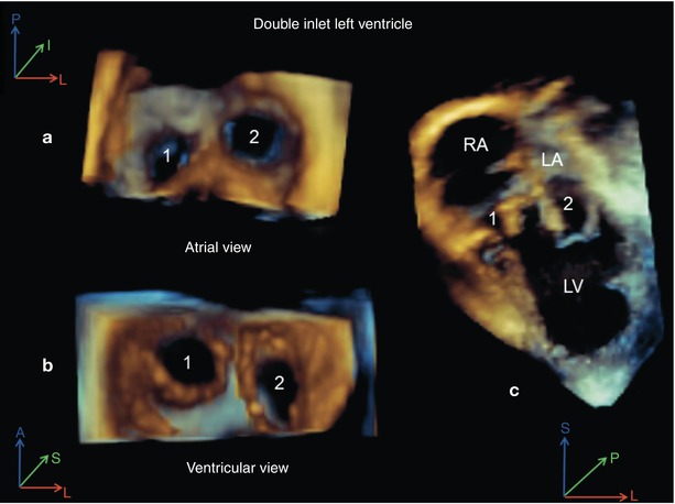

Fig. 20.11
Full volume 3D acquisition from a mid esophageal four chamber view in a patient with double inlet left ventricle. (a) View of both atrioventricular valves from the atrium. The right-sided atrioventricular valve is labeled (1) and the left-sided valve is labeled (2). (b) View of both atrioventricular valves from the ventricular aspect. (c) The mid esophageal four chamber view is depicted. LA left atrium, LV left ventricle, RA right atrium
Atrial Septal Defects
Analogous to 3D imaging of VSDs, imaging of atrial septal defects (ASDs) using 3D TEE employs en face and long axis views. In Fig. 20.12a, a 3D zoom en face view of a large inferior sinus venosus ASD is shown from the right atrial aspect. A superior type sinus venosus ASD with partial anomalous pulmonary veins is presented in Fig. 20.12b. This image was obtained from a modified mid esophageal bicaval view (probe has been withdrawn), using a cropped full volume 3D image.
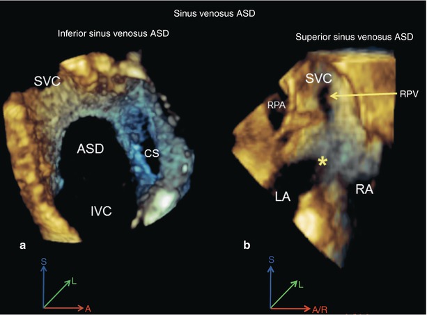

Fig. 20.12
Sinus venosus atrial septal defects. (a) A 3D zoom acquisition view of inferior sinus venosus atrial septal defect (ASD) is shown. (b) 3D full volume acquisition from a modified mid esophageal bicaval view (with probe withdrawal) of a superior sinus venosus ASD with anomalous drainage of the right pulmonary veins (RPV) into the superior vena cava (SVC). The inter-atrial communication is indicated by the asterisk . CS coronary sinus, IVC inferior vena cava, LA left atrium, RA right atrium, RPA right pulmonary artery
Applications During Interventional Cardiac Catheterization
The closure of secundum ASDs and muscular VSDs using interventional catheterization techniques has become commonplace at busy CHD treatment centers. The en face views of the septal anatomy and surrounding structures, as well as the ability of 3D TEE to visualize interventional procedure hardware rapidly and in rendered 3D detail, are quite helpful to guide the performance of these procedures. Currently, our interventional cardiology colleagues expect that we perform this analysis on a routine basis during these procedures. The 3D TEE acquisition modalities most useful during these tasks include 3D zoom and live 3D, both of which are live 3D modalities.
Case Examples
Transcatheter Closure of Secundum Atrial Septal Defect
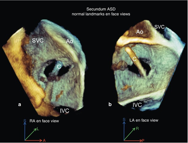
The en face views of the atrial septum acquired at the mid esophageal level using the 3D zoom mode are most useful during transcatheter ASD device closure. In a single view the dimensions, location, shape, rims, number of orifices, and important surrounding structures are demonstrated. This is illustrated in Fig. 20.13. This view is also very useful to monitor wire, catheter, and device manipulations. The common ASD rim deficiencies that can make device deployment challenging or impossible are presented in Fig. 20.14. Figure 20.14a, b display the usual 3D zoom en face views from a right atrial perspective. Figure 20.14c shows another very useful 3D TEE view used during transcatheter ASD device closure. This is a live 3D DTG Sagittal view that provides the best view possible of the inferior rim of the ASD. Multiple orifice secundum ASDs are not rare, therefore a collection of these is presented in Fig. 20.15 and Video 20.8. Lastly, views of the two most commonly used contemporary ASD closure devices are presented in Fig. 20.16, namely the Amplatzer (Video 20.9) and Helex devices.

