Circumferential Ablation with PV Isolation Guided by Lasso Catheter
Feifan Ouyang
Kazuhiro Satomi
Karl-Heinz Kuck
Dr. Kazuhiro Satomi is supported by the Research Grant Abroad of the Japan Heart Foundation and Japanese Society of Electrophysiology, and the Research Grant Abroad of St. Jude Medical and Fukuda Denshi. We thank Dr. Florian T. Deger for his assistance.
Recent studies have demonstrated that myocardium around the pulmonary vein (PV) ostia plays an important role in the initiation and perpetuation of atrial fibrillation (AF) (1). This important finding has led to the development of segmental PV ostial isolation (2,3), circumferential ablation (4), or isolation around the PVs guided by 3-D electroanatomic mapping (5). Also, substrate modification with the use of limited linear ablation (such as roof line and left isthmus line) (6,7) or ablations of the areas associated with complex fractionated electrograms (8,9) have been demonstrated to improve the clinical outcome after PV isolation in patients with AF inducibility.
The method most used in the majority of ablation centers is PV isolation either using segmental PV isolation or circumferential complete PV isolation guided by 3-D mapping. In these procedures the Lasso catheter recording within the PV plays an important role in identifying electrophysiological connections between the PV and the left atrium (LA). Also, electroanatomic mapping provides more precise information on the anatomy of atrial chambers and contributes to shorter fluoroscopic time.
In this chapter we describe our circumferential ablation technique for PV isolation guided by the Lasso catheter and electroanatomic mapping in patients with paroxysmal or persistent AF.
The ablation procedure is routinely performed under sedation with a continuous infusion of propofol in our center. Transesophageal echocardiography (TEE) is performed in all patients to rule out LA thrombi. Anticoagulation treatment with warfarin is stopped on admission and replaced by intravenous heparin to maintain partial thromboplastin time at two to three times higher than the control value in all patients. All procedures consist of the steps described below (5,10,11).
Transseptal Puncture
Three 8F SL1 sheaths (St. Jude Medical, Inc., Minnetonka, MN) are advanced to the LA by a modified Brockenbrough technique in the majority of patients: two sheaths over one puncture site and the third sheath via a second puncture site. One puncture is always performed at the inferoposterior site of the foramen ovale for easy access to the right inferior vein and the atrial myocardium (Fig. 9.1). After transseptal catheterization, intravenous heparin is administered to maintain an activated clotting time of 250 to 300 seconds. Additionally, continuous infusions of heparinized saline are connected to the transseptal sheaths (flow rate of 10 mL/h) to avoid thrombus formation or air embolism.
LA Reconstruction
Electroanatomic mapping is performed with a 3.5-mm-tip catheter (ThermoCool Navi-Star or ThermoCool, Biosense-Webster, Inc., Diamond Bar, CA) during coronary sinus (CS) pacing, sinus rhythm (SR) or AF by using the CARTO system
(Biosense-Webster, Inc.) or the NavX system (St. Jude Medical, Inc.). Mapping is only performed in the LA; all mapping points deep within the PV must be deleted to ensure that the posterior wall is flat in the right lateral and left lateral views (Fig. 9.2) during ablation.
(Biosense-Webster, Inc.) or the NavX system (St. Jude Medical, Inc.). Mapping is only performed in the LA; all mapping points deep within the PV must be deleted to ensure that the posterior wall is flat in the right lateral and left lateral views (Fig. 9.2) during ablation.
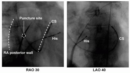 Figure 9.1. The right and left images show, respectively, fluoroscopic right and left anterior oblique views (LAO and RAO) during transseptal puncture. One puncture is always performed at the inferoposterior site of the foramen ovale for easy access to the right inferior vein and the atrial myocardium. CS, coronary sinus; His, His bundle; RA, right atrium. |
 Figure 9.2. The left upper and lower images show right lateral and left lateral 3D-MR views of the LA. The middle and right images show, respectively, electroanatomic maps of the LA in the right lateral and left lateral view before and after correction of map in same patient. The PV ostia (identified by angiography) are tagged by white dots. Note that (a) in the MR imaging view the ostium of the right superior pulmonary vein (RSPV) are more anterior than the ostium of the right inferior pulmonary vein (RIPV); (b) in the original map (middle images) the LA posterior wall is not flat due to many mapped points within the right- and left-sided PVs, whereas in the corrected map in the right images the LA posterior wall is very flat after the deletion of the points within the PVs on both sides; (c) the anterior wall is prominent due to points obtained with excessive pressure on the LA anterior wall in the original map in the middle image, whereas the anterior wall is smooth after the deletion of these points in the corrected map in the right image. RSPV, right superior pulmonary vein; RIPV, right inferior pulmonary vein; LSPV, left superior pulmonary vein; LIPV, left inferior pulmonary vein. See color insert 2. |
Selective Venography of PV and Identification of PV Ostium
After LA reconstruction, each PV ostium is identified by selective venography (Fig. 9.3) and carefully tagged on the electroanatomic map. We arbitrarily defined
any point with clear PV-LA inflection and marked the opposite points with perpendicularity to the PV on the right anterior oblique (RAO) 30° or left anterior oblique (LAO) 40° (Fig. 9.2). This step is the most important part to achieving a successful PV isolation. In our experience, the misunderstanding of the PV ostium may sometimes make the ablation more difficult or create a potential risk for PV stenosis. For example, the isolation of the left-sided PVs in the setting of a narrow ridge between the left atrial appendage and the left PVs can be very difficult if the anterior edge of the left PV ostia is inappropriately marked in the left atrial appendage. On the other side, severe PV stenosis can be produced if the PV ostium is tagged inside the PVs (12,13).
any point with clear PV-LA inflection and marked the opposite points with perpendicularity to the PV on the right anterior oblique (RAO) 30° or left anterior oblique (LAO) 40° (Fig. 9.2). This step is the most important part to achieving a successful PV isolation. In our experience, the misunderstanding of the PV ostium may sometimes make the ablation more difficult or create a potential risk for PV stenosis. For example, the isolation of the left-sided PVs in the setting of a narrow ridge between the left atrial appendage and the left PVs can be very difficult if the anterior edge of the left PV ostia is inappropriately marked in the left atrial appendage. On the other side, severe PV stenosis can be produced if the PV ostium is tagged inside the PVs (12,13).
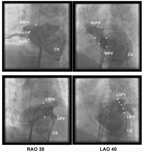 Figure 9.3. The images show, respectively, fluoroscopic right and left anterior oblique views (RAO and LAO) of the left atrium. The PV ostia are marked by points. The lines indicate the ablation line around the right-and left-sided PVs. CS, coronary sinus; RSPV, right superior pulmonary vein; RIPV, right inferior pulmonary vein; LSPV, left superior pulmonary vein; LIPV, left inferior pulmonary vein. |
 Figure 9.4. Fluoroscopic right and left anterior oblique views (RAO and LAO) show two Lasso catheters within right- and left-sided PVs, mapping catheter (Map) in left atrium and catheter inside coronary sinus (CS). Numbers indicate the location of the electrodes of the Lasso catheter. RSPV, right superior pulmonary vein; RIPV, right inferior pulmonary vein; LSPV, left superior pulmonary vein; LIPV, left inferior pulmonary vein. |
Double Lasso Technique
Two decapolar Lasso catheters (Biosense-Webster, Inc.) are placed within the ipsilateral superior and inferior PVs or within the superior and inferior branches of a common PV before radiofrequency (RF) delivery in the majority of patients with AF (Fig. 9.4). In our series of more than 1,300 AF ablations, in only 2% of patients could only one Lasso catheter be placed in the PVs due to very difficult transseptal puncture or manipulation of the sheaths.
The Lasso catheters within the ipsilateral PVs should be located with the catheter placed in a stable position to obtain a good signal during the procedure. If the Lasso catheter is placed too distally, the PV potential could be too small or unrecordable, especially in patients with a damaged atrium due to longstanding AF. If the Lasso catheter is located in the LA outside of the PV, it could result in misunderstanding of the LA and PV signal. In addition to the exact tagging of the PV ostium on the CARTO map, keeping in mind the Lasso catheter position and the placement of its electrodes enables mapping by using only an electroanatomic map without frequent use of fluoroscopy during the procedure, which contributes to shorter fluoroscopic and procedure time.
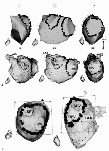 Figure 9.5. A: 3-D anatomic maps and MR images combined with CARTO map of the LA in a left lateral (LL), posteroanterior (PA), and right lateral (RL) view are shown. Note that (a) the angiographic ostia of all PVs are tagged with white points; (b) the right and left continuous circular lesions are marked by multiple red dots around the PVs; (c) the two brown dots located in the right posterior CCLs and in the left anterior CCLs indicate the sites of simultaneous isolation of the ipsilateral PV when both CCLs are complete. B: MRI-derived, virtual endoscopic views of the junction of the right- and left-sided PVs and LA on CARTO merge imaging are shown. The ostia of the RSPV and RIPV are shown in the left panel and LSPV, LIPV, and LAA in the right panel. Note that (a) the right and left CCLs are marked by multiple red dots around the PVs in the left and right panels; and (b) CCLs are located on the ridge between the left PV and the LAA in the right panel. CCLs, continuous circular lesions; RSPV, right superior pulmonary vein; RIPV, right inferior pulmonary vein; LSPV, left superior pulmonary vein; LIPV, left inferior pulmonary vein; LAA, left atrial appendage. See color insert 2. |
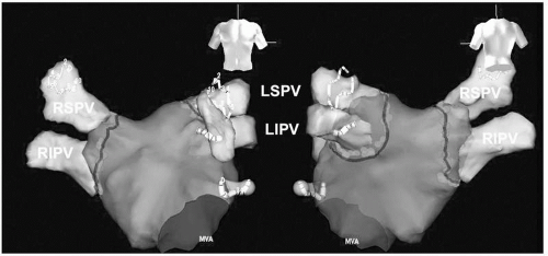 Figure 9.6. 3-D anatomic maps of the LA by NavX in posterior-anterior and anterior-posterior views. The angiographic ostia of all PVs are tagged with black lines. The right and left CCLs are marked by multiple red dots around the PVs. Two Lasso catheters are located in the left and right PVs to confirm isolation of both PVs. CCLs, continuous circular lesions; RSPV, right superior pulmonary vein; RIPV, right inferior pulmonary vein; LSPV, left superior pulmonary vein; LIPV, left inferior pulmonary vein; LAA, left atrial appendage; MVA, mitral valve annulus. See color insert 2. |
Continuous Circular Lines Surrounding the Ipsilateral PVs
Irrigated RF energy is delivered with a target temperature of 45°C, a maximal power limit of 40 W, and an infusion rate of 17 mL/min. In all patients, maximal power of 30 W is delivered to the posterior wall to avoid the potential risk of LA-esophageal fistula. RF ablation sites are tagged on the reconstructed 3-D LA. RF energy is applied for 30 seconds until the maximal local electrogram amplitude decreases to less than 70% or double potentials appear, and the sequence of PV activation recorded from the double Lasso catheters changes. RF ablation is performed in the posterior wall more than 1 cm and in the anterior wall ≈5 mm from the angiographically defined PV ostia (Figs. 9.5, 9.6).
Procedure Endpoint
More than 90% of right PVs are isolated by completing anatomic continuous circular lines (CCLs) alone, however 30% of left PVs are still conducted after the completed CCLs even in highly experienced physicians (Fig. 9.7). The remaining conduction gaps can easily be found with 3-D mapping and two Lasso catheters within the ipsilateral PVs. The additional applications at the conduction gap between the LA and PV are delivered according to the activation sequence of the Lasso catheters. In patients with paroxysmal or persistent AF, the ablation endpoint of CCLs is defined as absence of all PV spikes during SR documented with the two Lasso catheters within the ipsilateral PVs at least 30 minutes after PV isolation. Termination of AF is not included in the endpoint in our procedure. Electrical cardioversion is performed after complete isolation of the bilateral PVs in case of AF persistence.
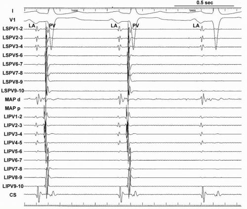 Figure 9.7. Tracings during sinus rhythm are ECG leads I, V1 and intracardiac electrograms recorded from two Lasso catheters within the left superior and inferior pulmonary veins (LSPV, LIPV), a mapping catheter (Map), a catheter inside the coronary sinus (CS) during RF application in a patient with paroxysmal AF. Note a simultaneous isolation of both LSPV and LIPV when the right CCLs are complete. CCLs, continuous circular lesions; LA, left atrium; PV, pulmonary vein. |
The double Lasso technique provides better information on LA-PV conduction and interesting electrophysiologic findings about the PV activation. This technique is also helpful for complete PV isolation by CCLs. The comprehension of the electrophysiologic findings recorded by the Lasso catheter is the most essential for electrophysiologic PV isolation. Careful analysis of the signal at the LA-PV is required to avoid a wrong interpretation.
Complete PV Isolation by CCLs
Our studies have demonstrated that CCLs can be performed during SR or CS pacing or during AF (5,11). During SR or CS pacing, CCLs resulted in progressive prolongation and sequence change of PV activation recorded from two Lasso catheters within ipsilateral PVs, and finally isolation of the ipsilateral PVs is achieved without amplitude reduction of the PV spike (Fig. 9.8). We immediately stop the RF application to avoid the potential risk of PV stenosis in case of ablation catheter dislodgement into the PV. In our previous experience without using double Lasso techniques, the application at the inside the PV causes to the attenuation of the PV signals or isolation of only the distal part of the PV and makes identification of the PV activation sequence more difficult (Fig. 9.9).
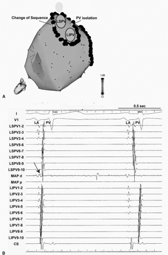 Figure 9.8. A: 3-D anatomic maps of the LA in a left lateral view. Note that (a) the left continuous circular lesions (CCLs) are marked by multiple red dots around the PVs; (b) the two sites with a brown dot located in the left posterosuperior CCL indicate the change of PV sequence and another brown dot in the left anterior CCLs indicates simultaneous isolation of the ipsilateral PVs. See color insert 2. B: Tracings during sinus rhythm are ECG leads I, V1 and intracardiac electrograms recorded from two Lasso catheters within the left superior and inferior pulmonary veins (LSPV, LIPV), a mapping catheter (Map), a catheter inside the coronary sinus (CS) during RF application in a patient with paroxysmal AF. Note: (a) the earliest activation of PV recorded by Map (arrow); (b) a sequence change of both LSPV and LIPV and all LIPV signals significantly delayed in the second beat compared to the first beat during the RF application at left anterior CCLs. C: Note: (a) a simultaneous isolation of both LSPV and LIPV when the left CCLs are complete at the left posterior region; (b) the earliest activation of PV recorded by Map (arrow). LA, left atrium, PV, pulmonary vein.
Stay updated, free articles. Join our Telegram channel
Full access? Get Clinical Tree
 Get Clinical Tree app for offline access

|