The purpose of this chapter is to provide direction in choosing the most appropriate pulse generator – pacemaker, internal cardioverter-defibrillator (ICD) or cardiac resynchronization therapy (CRT) – and leads for a given patient. It is not possible to provide guidelines that meet the needs of every patient; indeed, pulse generator selection, whether pacemaker, ICD, or CRT, must be individualized. Our goal is to provide practical considerations and a generic approach to determine the type of hardware most appropriate for the patient who is receiving an implantable cardiac device.
Pacemaker Selection
Pacemaker selection today involves a decision as to whether cardiac resynchronization is required. A significant proportion of patients receiving devices have combined abnormalities that may include chronotropic incompetence, atrioventricular (AV) nodal dysfunction, intraventricular conduction delay (electrical ventricular dyssynchrony), and the propensity for ventricular arrhythmia. Thus, decisions for patients requiring pacemakers may involve consideration and exclusion of the need for a defibrillator lead or a left ventricular (LV) pacing lead. The data supporting the hemodynamic benefits of cardiac resynchronization and the present indications are discussed in Chapters 2 and 3. In this chapter, after a brief summary of the generally used algorithm for deciding which pulse generator, mode selection, and leads are to be used, we point out specific issues relevant to cardiac resynchronization devices.
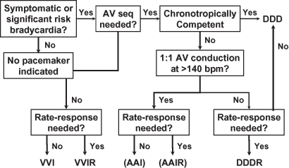
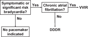
While substantive algorithms have been described for pacemaker mode selection (Figs 4.1 and 4.2)1, a simplified approach is presented here. For patients with chronic atrial fibrillation who require pacing, a single-chamber device with VVIR mode selection is preferred. For all other patients, a dual-chamber device with DDDR pacing and automatic mode switch to a non-tracking mode during paroxysms of atrial fibrillation is done. Occasionally, patients with limited longevity or highly limited activity levels may do best with a single lead and VVI or VVIR modes.2
Fig. 4.1 Algorithm for pacing mode selection that includes most available pacing modes. AV, atrioventricular; seq, sequential.
Even for a patient with another irreversible and possibly progressive medical illness and marked limitations in activity in whom a decision is made to implant a pacemaker, if VVI pacing results in pacemaker syndrome, the patient may actually feel worse. Although such an outcome may be impossible to predict, it should at least be considered and, at a minimum, blood pressures should be compared in the native underlying rhythm vs. ventricular pacing.
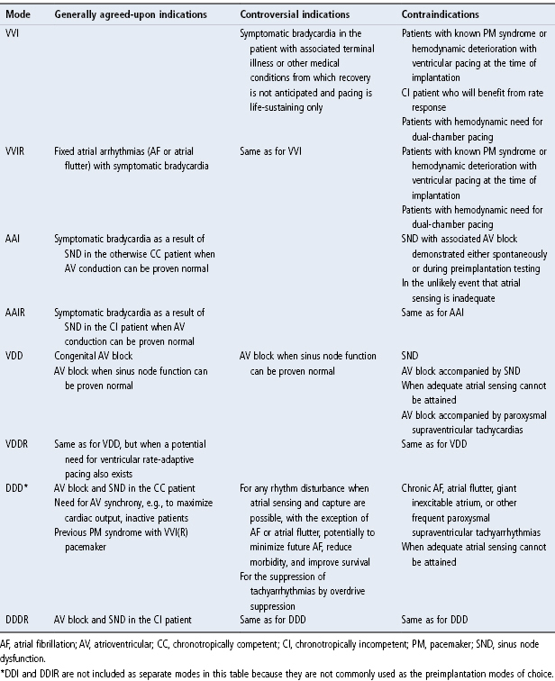
At one time there were significant cost differences between simpler devices (VVI) and those that had rate-adaptive pacing, etc. Today, these differences are largely negligible in most parts of the world, and the main decision that needs to be made is whether a single-chamber device will suffice (chronic atrial fibrillation). Internationally, however, the simplest device (single-chamber non-rate-adaptive) may be necessary to save lives amidst more significant economic constraints. In most practices, however, devices retaining options for more complex pacing requirements are placed and programmed “on” when required (Table 4.1).
Table 4.1 Indications for various pacing modes.
Symptomatic Bradycardia
For most patients with bradyarrhythmias requiring pacing who do not have chronic atrial fibrillation, a dual-chamber pacemaker is indicated. Using a dual-chamber pacemaker with rate-adaptive capabilities (DDDR) in all patients provides the greatest long-term flexibility, and most patients with symptomatic bradycardia often have associated chronotropic incompetence or at least the potential for this to occur. In some situations, however, rate-adaptive pacing is essential, including dual-chamber devices placed specifically for patients with sick sinus syndrome and fatigue from documented chronotropic incompetence and patients with chronic atrial fibrillation with slow ventricular rates. Because rate responsiveness in patients with chronic atrial fibrillation depends on autonomic regulation of the AV node (poorly regulated), these patients necessarily require sensor-driven pacing. For example, if chronic atrial fibrillation with a slow ventricular response develops at a later date, the DDDR pacemaker could be reprogrammed to VVIR. A DDD pacemaker, which has no rate-adaptive capability, could be programmed only to VVI, potentially a suboptimal option.
Pure Sinus Node Dysfunction
For the patient with pure sinus node disease, i.e., no documented or provocable abnormalities in AV nodal conduction, AAIR pacing may be appropriate. (Preimplantation criteria for AAI/AAIR pacing are described in Chapter 3.) If preimplantation testing has established normal AV nodal conduction, the annual risk of AV block developing is 1–2%.3,4 If AV block develops, another procedure is required to implant a ventricular lead and upgrade the pacemaker. This additional procedure is obviated if a DDDR pacemaker is used initially.
Although DDDR pacing gives the most flexibility of options, some disadvantages of placing a ventricular lead and pacing the right ventricle require consideration. The adverse effects of right ventricular pacing are discussed in Chapter 2: Hemodynamics, and ventricular avoidance pacing algorithms are discussed in Chapter 7: Timing Cycles and Chapter 8: Programming.
Pure Atrioventricular Block
For the patient with pure AV node disease, i.e., no documented abnormalities in sinus node behavior, VDD or VDDR pacing may be appropriate. Specifically, the patient with congenital complete heart block may do well with VDD(R) pacing.5,6 As before, a problem arises if sinus node dysfunction develops in the future, resulting in a suboptimal pacing mode without reasonable programming options. However, from a “hardware” perspective, use of a single-lead VDD or VDDR pacing system helps to minimize the amount of hardware needed. This can be especially important for pediatric patients.
Single-pass VDD(R) systems are occasionally favored in pediatric patients, but otherwise this pacing mode is not commonly used. Single-pass VDD leads, i.e., atrial sensing occurs via “floating” electrodes in the atrialized portion of the lead, have generally been passive fixation leads, and for pediatric patients many implanters, including our institution, would prefer active-fixation leads.
It should be mentioned that single-pass leads have also been used for DDD pacing, i.e., the floating atrial electrodes are capable of pacing and sensing.7 This approach to DDD pacing has never been widely embraced. Concerns have been the requirement for high atrial outputs in order to achieve capture and phrenic nerve stimulation. Placing a single-pass DDD lead in the coronary sinus has also been attempted for left atrial and left ventricular stimulation.8
Neurocardiogenic Syncope and Carotid Sinus Hypersensitivity
If a patient requires pacing for neurocardiogenic syncope, whether the vasovagal variety or carotid sinus hypersensitivity, dual-chamber pacing is necessary for several reasons.9–11 In a patient with vasovagal syncope that most likely has some component of vasodepression together with the cardio-inhibition that requires pacing, ventricular pacing alone could result in pacemaker syndrome and further aggravate symptoms caused by hypotension. The bradycardia that occurs in patients with carotid sinus hypersensitivity may be due to either AV block or sinus arrest. Therefore, ventricular pacing support is required, and dual-chamber pacing is superior for the reasons already noted. For specific programmable options that are desirable when pacing patients with these disorders see Chapter 8: Programming and Chapter 7: Timing Cycles.
Choosing Specific Programmable Options
Programming and the wide variety of programmable options available in current devices are covered in Chapter 8: Programming.
Choosing the Rate-Adaptive Sensor
When choosing hardware for a specific patient, there may be advantages of one rate-adaptive sensor over another. This is discussed in Chapter 9: Rate-Adaptive Pacing.
Choosing the Lead or Leads
A detailed discussion of the merits of various lead types is beyond the scope of this chapter, as is a thorough discussion of the evolution of pacing leads. Rather, the purpose of the chapter is to provide the reader with an understanding of the types of leads that are available and future trends that are likely to be seen.
With the exception of a few specific circumstances, choice of the pacing lead or leads becomes one of personal preference and personal bias. Choice of pacing leads should also be based on performance data of the specific model. Options that must be considered for all leads are as follow:
- Type of insulation: silicone or polyurethane or a “hybrid” combination (such as in a bipolar coaxial lead where the inner and outer insulations are different materials)
- Mechanism of fixation: active or passive
- Polarity: unipolar or bipolar
- Compatibility of lead and pulse generator connection system.
Choice of an atrial pacing lead must take into account insulation, fixation, polarity, and whether the lead is straight or preformed J type (Fig. 4.3). The same decisions must be made for choice of the ventricular lead, except that right ventricular leads are straight (Fig. 4.4). Specific issues related to LV pacing are discussed below.
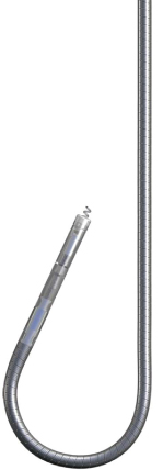
Fig. 4.4 (A) Active fixation lead which could be used in either chamber; active fixation leads may be straight or preformed J, unipolar or bipolar. Preformed J leads are used only in the atrium, and straight active fixation leads may be used in either chamber. The fixation mechanism varies, that is, the screw may be retractable or nonretractable. In some, the nonretractable screw is coated with a material that dissolves once in the bloodstream. This allows the lead to be passed into the heart without an exposed screw catching on the vascular tree. (B) Passive fixation lead which is typically used for right ventricular pacing. Passive fixation leads may also be unipolar or bipolar. Tines represent the nearly exclusive passive fixation mechanism used in contemporary passive fixation leads.

Threshold Reduction
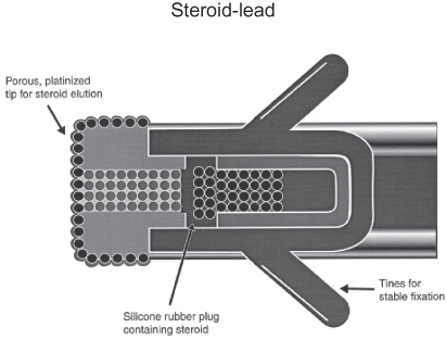
Although multiple mechanisms have been used to achieve lower thresholds, steroid elution has been the most successful and most widely used method for threshold reduction.12,13 Steroid elution has been accomplished in several ways, such as from a steroid-saturated silicone plug within the lead’s tip electrode or from a steroid-eluting collar adjacent to the tip electrode (Fig. 4.5). Steroid elution significantly minimizes the post-implant pacing threshold increases and peaking that typically occurs with nonsteroid-eluting electrodes. The steroid-eluting plug or collar contains a very small amount of steroid, e.g., <1 mg dexamethasone sodium phosphate or dexamethasone acetate, which does not have any systemic effect. Steroid elution is available on atrial and ventricular leads with both active and passive fixation means, and is also available in coronary venous and epicardial leads. In nearly all institutions, steroid-eluting leads are used routinely.
Fig. 4.5 Diagrammatic representation of a steroid-eluting lead. Steroid (dexamethasone) is slowly eluted through the porous, platinized tip of a silicone rubber plug.
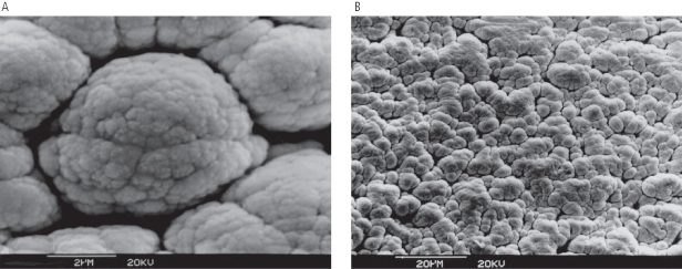
Fractal coating (Fig. 4.6) and other techniques have also been used to lower pacing thresholds.
Fig. 4.6 Magnified images of a fractally coated electrode: (A) at 2 µm; (B) at 20 µm. The fractal surface of the lead electrodes creates a larger effective surface area, and as a result maximizes the myocardial interface, which is a major factor in determining a lead’s sensing characteristics.
Lead Polarity
Unipolar leads have an electrode at the tip that functions as the cathode and the pulse generator serves as the anode. Bipolar leads have a both electrodes within the heart – the tip electrode functions as the cathode and a ring electrode proximal to the tip functions as the anode. Because the unipolar lead has a large interelectrode distance or a “big antenna,” they are more susceptible to sensing of intracardiac and extracardiac far-field signals than bipolar leads.
Bipolar leads are used more frequently in the USA. This preference exists largely because of a lower susceptibility to electromagnetic interference and other far-field signals when pacemakers are in a bipolar sensing configuration.14–16 If examined over decades of use, bipolar leads have had an overall higher incidence of failure than unipolar leads, largely because of the specific bipolar leads which utilized the 80A version of polyurethane that failed in high numbers in the 1980s. If these leads were excluded from the analysis, the survival difference between unipolar and bipolar leads would be minimal.
The interelectrode distance of a bipolar lead also deserves consideration. This distance may not only affect the duration of the intracardiac electrogram signals, but it also usually has an effect on the amplitude and slew rate of the electrogram’s signals, depending on the low- and high-frequency band pass filters in the input amplifiers of the device. A lead with a greater distance between electrodes will generally have larger amplitude far-field signals (i.e., R-waves sensed on an atrial lead). This characteristic may affect the reliability of mode switching. In pacing systems with more than one ventricular sensing lead, i.e., pacemaker and ICD in the same patient or ICD with biventricular pacing, minimizing far-field signals may also be of increased importance.
Electrode Design
The choice of electrode material is guided by the metal–tissue impedance properties, tissue fibrotic reaction, long-term function, and susceptibility to corrosion. Platinum, platinum-iridium and Elgiloy (an alloy of cobalt, chromium, molybdenum, manganese, nickel, and iron) are commonly used. However, these metals are prone to corrosion in the body. Vitreous carbon electrodes are inert and have been shown to have lower chronic thresholds than platinum electrodes.
The impedance of the electrode–tissue interface is determined by electrode material, tissue characteristics, and electrode surface area in contact with tissue. Older leads had a large electrode surface area which resulted in low lead impedance resulting in high current drain and high pacing threshold. Contemporary electrode tips employ very a small surface area (e.g., the Medtronic CapSure 5054 lead has a 1.2-mm2 electrode tip) which results in a high current density at the tip, higher lead impedance, lower pacing threshold, and improved generator longevity. Contemporary tip electrodes are made porous by using sintered or laser drilled tips. Porous electrodes have lower pacing threshold and dislodgement rates than smooth-tipped electrodes.
Lead Conductor
The conductor is made of a high strength material such as MP35N (alloy of nickel, cobalt, chromium and molybdenum) made into a coil or drawn into a cable. Unipolar leads have one and bipolar leads have two conductors. Bipolar lead conductors can be arranged in parallel or coaxially. Coaxial leads have a central lumen that allows passage of a stylet for ease of lead placement. Traditionally, the two conductors in a coaxial bipolar lead were arranged concentrically and each surrounded by insulation material which resulted in bulkier and stiffer lead bodies. Current coaxial leads employ thin ETFE (ethylene tetrafluoroethylene) insulation on each conductor wire, such that both wires can be coiled into a single coil to reduce lead diameter and increase flexibility.
Lead Insulation
With few exceptions, the materials that have been used for most pacing leads for almost five decades are silicone rubber and polyurethane. Historically, both have generally had excellent performance records. Table 4.2 compares the basic characteristics of silicone rubber and polyurethane. When first introduced, polyurethane insulated leads were widely used by many implanters because they could be designed to have a smaller lead body diameter than many of the contemporary silicone rubber insulated leads and were said to handle better when two leads were implanted due to their greater lubricity in the body. Improvements in silicone insulation and use of lubricious coatings have made these differences less significant.
Table 4.2 Lead insulation: comparison of silicone rubber and polyurethane.
| Silicone rubbe | Polyurethane |
| Advantages | |
| Performance record >30 years Excellent biostability Flexibility | High tear strength High cut resistance Low friction in blood High abrasion resistance Inherently less thrombogenic Superior compressive properties |
| Disadvantages | |
| Tears easily Abrades easily Cuts easily Higher friction in blood Subject to cold flow failure More thrombogenic | Relatively stiff (55D) Potential for environmental stress cracking (true for Pellethane 80A) Potential for metal ion oxidation (true for Pellethane 80A and 55D) More susceptible to cautery heat damage |
Manufacturers often make the same lead available with either silicone or polyurethane outer insulation. Implanters base their choice on past experience, ideally taking into account product surveillance reports that detail the survival of specific leads. Not all agree on what is advantageous or disadvantageous about the characteristics of the insulating material.
For silicone rubber, being “very flexible” may or may not be an advantage. This quality means that something else in the design, such as the conductor coil, must increase the stiffness of the lead to the optimal value. A lead that is too flexible can damage the heart with excessive movement and may cause lead dislodgment or deterioration of the lead’s electrical parameters. A lead that is too stiff may cause perforation or dislodgment. A stiff conductor coil can be more prone to fracture. Some currently available bipolar coaxial leads utilize both silicone (inner insulation) and polyurethane (outer insulation) to benefit maximally from both their properties. A new insulation material, created specifically for cardiac leads, is available and used in various types of leads, which is a silicone rubber–polyurethane copolymer (Optim®; St Jude Medical, Inc.).
“Smaller diameter possible” is not included in Table 4.2 because it is neither an advantage nor a disadvantage. It is the result of the polymer’s mechanical properties such as high tear strength and higher stiffness. That is, even if silicone rubber had the same tear strength as polyurethane, smaller diameter insulation could make a lead like a whipsaw. Higher stiffness allows a thinner tube to maintain high torque strength for implantability, but the thinner tube makes the structure more flexible in bending. Therefore, an advantage of polyurethane in certain designs is “higher stiffness” combined with “higher tear strength.”
Polyurethane has vastly superior compressive properties, specifically low creep or “cold-flow.” It is also much less prone to abrasion from physical rubbing contact with other leads or the device. In addition, some believe that polyurethane is inherently less thrombogenic than silicone rubber. Although silicone rubber has been available longer, polyurethane has been used in humans as lead insulation for >30 years.
Polyurethane has been available in a softer, more flexible version known as “80A” and a harder, less flexible version known as “55D.” Early leads made with the 80A polyurethane exhibited higher levels of degradation of the polyurethane insulation. Most current polyurethane leads utilize the 55D version insulation, which is much less prone to the degradation.
Silicone rubber is sometimes criticized for “absorbing lipids (calcifications).” Although lipid absorption is reported in the literature for ball and cage heart valves, it has not been proven to be clinically significant in pacing leads and does not appear to result in failures. Lipid absorption and calcification are two different phenomena. Even though mineralization of encapsulating sheaths (extrinsic mineralization) is common, there is no evidence that it causes lead insulation failure (although it greatly hinders removal of old leads). Mineralization of the silicone rubber per se (intrinsic mineralization) has also been rarely observed, but lead failures from this mechanism have been very rare.
Polyurethane, being “relatively stiffer,” is often used advantageously, especially in a portion or certain segment of a lead, and allows manufacturers to make smaller, tough leads that can have greater torquability, resulting in easier implantability.
At one time, not being “repairable” was a disadvantage for polyurethane insulated leads vs. silicone leads. In the earlier years of cardiac pacing, experienced individuals would at times attempt outer insulation repair of silicone rubber insulated leads with medical adhesive and silicone film. This worked relatively well if done correctly. Also, terminal pin replacement on unipolar leads could be performed, if necessary, with specific repair “kits” from the manufacturers. At this time, repair of any portion of the lead should not be attempted. If a lead is malfunctioning or grossly damaged, it should be abandoned and capped, or extracted and replaced.
Although no longer a significant issue, “sensitivity to manufacturing process” can also be a disadvantage for both materials. Knowledge is required to work with either one. The potential for environmental surface cracking remains true for the 80A polyurethane, but is not a significant mechanism of clinical failure in contemporary 55D polyurethane leads. The potential for metal ion oxidation remains an issue for contemporary 55D polyurethane insulated leads. Despite a blemish on polyurethane leads due to a high failure rate in the 1980s of the 80A version of polyurethane, the overall survival rate for other, newer polyurethane leads utilizing the 55D version has been excellent.17,18
What is an acceptable rate of lead failure? Ideally, leads would never fail, but this level of reliability will never be reached. The acceptable failure rate for permanent pacing and defibrillation leads (and pulse generators for that matter) is a matter of continued debate.19 During the preparation of this text there were a number of leads and pulse generators that were placed on advisory status, which has significantly fueled this debate. Some experts have suggested that no worse than 5% cumulative failure rate at 10 or 20 years should be goals for ICD and pacing leads, respectively. However, at this time, no specific acceptable failure rate can be quoted for any component of a pacing, defibrillation, or CRT system.
Lead Diameter
Over the years the diameter of pacing leads has decreased. In general, lead diameters have decreased over the years, and while this is of benefit for ease of vascular access and preventing tricuspid regurgitation, SVT stenosis, etc., lead failure and lack of pain with manipulating with very small leads are potential disadvantages. There is still significant variation in the lead body size. Contemporary stylet-driven leads are commonly in the range of 4.5–7 Fr in size. Lead selection may be driven by “size” in some patients. It may be advantageous to use preferentially a small-diameter lead in children and in patients with existing transvenous leads in whom the vessel lumen is compromised.
More recently, a lumenless pacemaker lead (SelectSecure lead model 3830, Medtronic, Inc.) (Fig. 4.7) has become available which replaces the coil cathode with a cable conductor (Fig. 4.8). The lead is delivered using a deflectable catheter (deflectable model 10600 catheter, Medtronic, Inc.) without the use of a stylet. This allows for further reduction in lead diameter (4.1 Fr), increased lead body tensile strength, site-specific lead placement, and lead extraction without locking stylet. Implantation of this lead was shown to be feasible, but preliminary data suggest higher implantation complications including lead dislodgement and cardiac perforation as well as higher, but acceptable, pacing thresholds at 18 months’ follow-up. Long-term experience with the lead is limited at this time.20
Fig. 4.7 An example of a lumenless lead, SelectSecure™, Medtronic, Inc., that is not stylet driven. Instead, the lead is advanced through a deflectable sheath that is maneuvered to the specific site of interest. The lead is then passed through the sheath and the helix advanced into the myocardium at that site.
(Used with permission from Medtronic, Inc.)
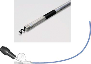
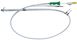
Fig. 4.8 Passive fixation bipolar single-pass VDD lead. Note that in the portion of the lead that will be positioned within the atrium, there are two ring electrodes (arrows). Sensing occurs via these “floating” atrial electrodes and allows P-synchronous pacing with a single lead.
Compatibility of Lead and Pulse Generator
The pacemaker lead or leads and pulse generator selected do not need to be from the same manufacturer. It is generally acceptable to “mix and match” leads from company X with a pulse generator from company Y, assuming similar functionality. What is mandatory is that the lead connector be compatible with the connector cavity of the pulse generator.
Historically, unipolar leads were 5 or 6 mm in diameter and bipolar leads were of the bifurcated design with similar 5 or 6-mm sizes. Most leads currently used are of “inline” bipolar design with a 3.2-mm diameter (Fig. 4.9). In 1986, a voluntary standard for lead connectors and connector cavities was established. This voluntary standard for leads and connectors incorporated sealing rings on a 3.2-mm lead connector and is referred to as VS-1.21
Stay updated, free articles. Join our Telegram channel

Full access? Get Clinical Tree


