Chest Tubes
Chest tubes are frequently used in the practice of pulmonary medicine. Indeed, in 1995, it was estimated that 1,330,000 chest tubes were placed in the United States (1). However, it has been my impression that many medical personnel do not understand how the drainage system for chest tubes functions and how to troubleshoot problems with chest tubes. In this chapter, the various methods of inserting chest tubes are discussed, followed by a more in-depth discussion of the different drainage systems used with chest tubes, plus recommendations for troubleshootingrelated problems. The indications for chest tube insertion with pneumothorax, hemothorax, empyema, and malignant pleural effusion are discussed in the respective chapters on these entities.
CHEST TUBE SIZE
In general, there has been a tendency over the past decade to use smaller (10-14 F) chesttubes (2,3,4). The advantages of the small-bore catheters are that they are easier to insert and there is less pain with their insertion and while they are in place. Small-bore chest tubes are recommended when pleurodesis is performed. Small-bore chest tubes are also recommended for the treatment of pneumothorax. However, patients on mechanical ventilation with barotrauma induced pneumothoraces are best managed with large-bore chest tubes (2). Small-bore catheters are also recommended for complicated parapneumonic effusions (5). When a small-bore chest tube is used to treat a complicated parapneumonic effusion, it should be flushed with 20 to 30 ml saline every 6 hours via a three-way stopcock (5). Patients with hemothorax are best managed with large-bore (>20 F) chest tubes because of blood clots and the high volume of pleural fluid (2). In the largest series (6) to date, 1,092 patients had (12 F) catheters inserted using guidewires. The percentages of successful cases were 93.8% of 324 malignant effusions, 93% of 399 pneumothoraces, 92.3% of 272 nonmalignant effusions, and 74.2% of 97 empyemas (6).
CHEST TUBE INSERTION
In general, chest tubes are inserted into the pleural space by four methods: tube thoracostomy with a guidewire and dilators, tube thoracostomy with a trocar, operative tube thoracostomy, and tube thoracoscopy through a single-port thoracoscope. There are no controlled studies comparing the efficacy of the different methods of placing chest tubes (2). It has been recommended that most chest tubes be placed in the “triangle of safety” which is the area bordered by the lateral edge of the latissimus dorsi and the lateral border of the pectoralis major and superior to the horizontal level of the fifth intercostal space (4). This position minimizes the risk to underlying structures and avoids damage to muscle and breast tissue.
Training Requirements
The guidelines from the American College of Chest Physicians recommend that trainees should perform at least 10 procedures in a supervised setting to establish basic competency. Then to maintain competency, dedicated operators should perform at least five procedures per year (7).
Guidewire Tube Thoracostomy
This is probably the easiest way to insert a chest tube. In many hospitals, chest tubes are inserted by a radiologist, who uses this technique with either ultrasound
or computed tomography (CT) guidance (8,9). Commercial kits are available for guidewire tube thoracostomy. This procedure uses the Seldinger technique with guidewires and dilators (10). In general, after the skin, periosteum, and parietal pleura are anesthetized as is done for pleural biopsy (see Chapter 28), an incision is made in the skin that is ample to permit passage of the chest tube of desired size (Fig. 29.1A). Then, an 18-gauge needle attached to a syringe is introduced into the pleural space. Fluid or air is aspirated to confirm the intrapleural position (Fig. 29.1B). The syringe is removed, and the “J” wire is threaded through the needle in the desired direction into the pleural space (Fig. 29.1C). The needle is then removed, and more local anesthetic is injected into the intercostal muscles surrounding the wire. The smallest dilator is inserted, and with a rotating movement, it is advanced into the pleural space over the guidewire (Fig. 29.1D). The wire should always project out beyond the end of the dilator or inserter. The first dilator is removed, leaving the wire in place. Then the next size dilator is advanced over the guidewire into the pleural space and removed. Finally, the chest tube containing the inserter is threaded over the guidewire (Fig. 29.1E). The tube should pass readily, following the path made by the dilators and guided by the wire (10). It is important to make certain that all of the side holes in the tube are in the pleural space.
or computed tomography (CT) guidance (8,9). Commercial kits are available for guidewire tube thoracostomy. This procedure uses the Seldinger technique with guidewires and dilators (10). In general, after the skin, periosteum, and parietal pleura are anesthetized as is done for pleural biopsy (see Chapter 28), an incision is made in the skin that is ample to permit passage of the chest tube of desired size (Fig. 29.1A). Then, an 18-gauge needle attached to a syringe is introduced into the pleural space. Fluid or air is aspirated to confirm the intrapleural position (Fig. 29.1B). The syringe is removed, and the “J” wire is threaded through the needle in the desired direction into the pleural space (Fig. 29.1C). The needle is then removed, and more local anesthetic is injected into the intercostal muscles surrounding the wire. The smallest dilator is inserted, and with a rotating movement, it is advanced into the pleural space over the guidewire (Fig. 29.1D). The wire should always project out beyond the end of the dilator or inserter. The first dilator is removed, leaving the wire in place. Then the next size dilator is advanced over the guidewire into the pleural space and removed. Finally, the chest tube containing the inserter is threaded over the guidewire (Fig. 29.1E). The tube should pass readily, following the path made by the dilators and guided by the wire (10). It is important to make certain that all of the side holes in the tube are in the pleural space.
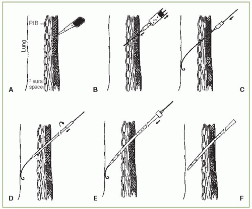 FIGURE 29.1 ▪ Guidewire tube thoracostomy. A: Making a small skin incision slightly larger than the diameter of the chest tube. B: Introduction of 18-gauge needle into the pleural space. C: Insertion of wire with “J” end into the pleural space. D: With guidewire in place, the tract is enlarged by advancing progressively larger dilators over the wire guide. Introduction of the dilators is facilitated by rotating and advancing the dilators in the same plane of the wire guide. E: Introduction of the chest tube inserter or chest tube assembly over the guidewire. F: The guidewire and the chest tube inserter have been removed, leaving the chest tube positioned within the pleural space. |
Once the tube is in place, the inserter and the guidewire are withdrawn (Fig. 29.1F). The tube is then clamped until it is attached to the chest drainage system. The tube is anchored in place by means of a long suture through the skin and around the tube. The incision is sutured without tension to avoid necrosis of the skin next to the tube. The operative area is cleaned and is covered with plain 4 × 4 gauze pads.
The gauze is then covered with tape, and additional fixation of the tube is obtained by the tape.
The gauze is then covered with tape, and additional fixation of the tube is obtained by the tape.
There are many different types of chest tubes that can be inserted with the technique mentioned in the preceding text. Kits are made so that chest tubes from 8.0 to 36.0 F can be inserted. The kits with the smaller chest tubes (<12.0 F) have no dilators. Some catheters have different characteristics. For example, with the Wayne Pneumothorax Set (Cook Medical Incorporated, Bloomington, IN), a 10.2 or 14.0 F size catheter is inserted over a 19-gauge needle; the catheter with this set is curved at the end like a pig’s tail, and hence the name pigtail catheter. The Thal-Quick Chest Tube Sets come with chest tube sizes from 8.0 to 36.0 F (Cook Medical Incorporated, Bloomington, IN, 800-457-4500, www. cookcriticalcare.com).
Trocar Tube Thoracostomy
This method is similar to the guidewire tube thoracostomy, except that there is no guidewire or dilators. In general, it is not recommended because its use appears to be associated with more complications (1). This method initially requires a 2- to 4-cm incision parallel to the superior border of the rib through the skin and subcutaneous tissues after local anesthesia is obtained. The trocar can then be inserted between the ribs into the pleural cavity, with the flat edge of the stylet tip cephalad to prevent damage to the intercostal vessels (Fig. 29.2A). Because significant force is often required to insert the trocar, the hand not applying the force should be placed next to the patient’s chest wall to control the depth of penetration. Once the trocar is in the pleural space, the stylet is removed. When the stylet is removed, the operator should immediately cover the trocar with the thumb to prevent a pneumothorax. Then, when the operator’s thumb is removed, the chest tube, with its distal end clamped, is quickly inserted into the pleural space (Fig. 29.2B). The trocar is removed by sliding it back over the tube. When the trocar has been removed from the chest, the chest tube is clamped between the trocar and the chest wall so that the clamp on the distal end of the chest tube can be removed. The chest tube must remain clamped until it is attached to an underwater seal to prevent air from entering the pleural space.
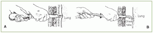 FIGURE 29.2 ▪ Trocar tube thoracostomy. A: Insertion of trocar into the pleural space. Note the position of the hands, the position of the trocar relative to the ribs, and the cephalad position of the flat edge of the trocar. B: Insertion of chest tube through the trocar. |
An alternate trocar method uses a chest tube with a trocar positioned inside the tube. The procedure with this apparatus is similar to that already detailed. Once the pleural cavity is entered, the inner trocar is gradually removed from the chest tube. When the proximal end of the trocar clears the chest wall, a clamp is placed between the trocar and the chest wall until the trocar can be completely withdrawn and the tube attached to a water-seal drainage system.
Operative Tube Thoracostomy
Dev et al. (11) have created an excellent video on performing operative tube thoracostomy, and watching this video is recommended before one performs their first operative tube thoracostomy. With this method, an incision is made in the chest wall, and then after blunt dissection with a hemostat, the operator places his finger into the pleural space to break adhesions between the lung and chest wall and to ascertain the position of the chest tube. It is a more extensive procedure than guidewire tube thoracostomy or trocar tube thoracostomy, but it is probably safer. The most serious complications of tube thoracostomy are insertion of the tube ectopically, namely, into the lung, stomach, spleen, liver, or heart. These complications are more likely when a trocar chest tube is used. With the operative method, digital exploration of the insertion site delineates whether the tract leads into the pleural space and whether any tissue or organ is adherent to the parietal pleura at the planned site of tube insertion (12).
It is important to emphasize that operative tube thoracotomy can be very painful. Therefore, it is recommended that patients be given a narcotic or an anxiolytic medication 10 to 15 minutes before the procedure and that liberal doses of local anesthetic be used (13). To perform an operative tube thoracostomy, a 3- to 4-cm incision is made in the skin parallel to the chosen intercostal space. The incision should be made down to the fascia overlying the intercostal muscle. This fascia is then incised throughout the length of the incision, with care taken not to cut the muscle. Once the fascia has been incised, the muscle fibers are spread with a blunt-tipped hemostat until the intercostal interspace is identified. Then, an incision is made in the intercostal fascia just above the superior border of the inferior rib over which the tube will pass. The parietal pleura is then penetrated by pushing a blunt-tipped hemostat through it. The hole in the parietal pleura is then enlarged by means of the operator’s index finger (Fig. 29.3A). At this time, the operator should palpate the adjacent pleural space to detect any adhesions. Then, the chest tube with its distal end clamped is inserted into the pleural space. A hemostat is used to guide the tube into the pleural space as the operator’s finger is withdrawn (Fig. 29.3B). The last hole in the chest tube should be at least 2 cm inside the pleural space. The tube is sutured in place, and the incision is cleaned as in guidewire tube thoracostomy.
Single-Port Thoracoscopy
A novel means by which chest tubes can be inserted is through a single-port thoracoscopy. Zgoda et al. (14) placed a sterile Hopkins rod-lens telescope (Karl Storz-Endoskope, Tuttlingen, Germany) into the most proximal port of a 28-F chest tube (Fig. 29.4). Then under direct visualization, the chest tube was placed into the costodiaphragmatic gutter and the telescope was removed. It is important to use a rigid scope for this procedure. A flexible pleuroscope should not be used because of its larger diameter and potential for damage to the distal flexible portion of the scope when placed or removed from within the chest tube (14). It would be my guess that this procedure will be used more frequently for the insertion of chest tubes by individuals who are adept at thoracoscopy. The great advantage is the visualization of the place where the tube will be placed.
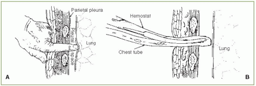 FIGURE 29.3 ▪ Operative tube thoracostomy. A: The physician’s index finger is used to enlarge the opening and to explore the pleural space. B: Placement of chest tube intrapleurally using a large hemostat. |
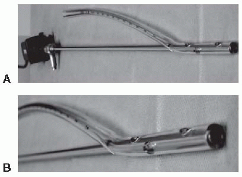 FIGURE 29.4 ▪ A: Hopkins rod-lens telescope is loaded into the most proximal port of a 28 F chest tube. This allows for the direct visualization of chest tube placement. B: Close-up of Hopkins rod-lens telescope positioned through the most proximal port of the chest tube. (From Zgoda MA, Lunn W, Ashiku S, et al. Direct visual guidance for chest tube placement through a single-port thoracoscopy: a novel technique. Chest. 2005;127:1805-1807, with permission.) |
Verification of Chest Tube Placement
After the chest tube has been inserted and connected to a drainage system, a chest radiograph should be obtained to verify the correctness of its position. Ideally, both a posteroanterior (PA) and a lateral view should be obtained because certain ectopic locations may not be apparent on the PA view alone (15). A CT scan should be obtained when the chest tube does not drain adequately and the chest radiograph is noncontributory (16). With CT, the tube can be visualized over its entire course with accurate location of its tip (16). If there are undrained locules of fluid, additional chest tubes can be inserted (8). Interestingly, chest tubes frequently end up in the fissures, even with operative tube thoracostomy. Curtin et al. (17) reviewed the PA and lateral chest radiographs in 50 patients who had 66 chest tubes placed in the emergency room for trauma. They reported that 38 of the 66 chest tubes (58%) were within a fissure. There was no evidence, however, that the presence of the tube within the fissure decreased its functional effectiveness (17). It is possible that some of the chest tubes were not in the fissures originally but became positioned in the fissures after the fluid was drained.
PLEURAL DRAINAGE SYSTEMS
Chest tubes are inserted into the pleural space to evacuate air or fluid. Because the pleural pressure is usually negative, at least during part of the respiratory cycle, various methods have been developed to prevent air from entering the pleural space when the pleural pressure is negative but to permit air or fluid, or both, to drain from the pleural space continuously. When managing patients with chest tubes, one must understand how these various drainage systems operate. In the past, the bottle system (described later) was used for pleural drainage. Commercially manufactured collection systems have subsequently replaced the bottle system. Nevertheless, the bottle system is described in detail because all the commercially manufactured systems are based on the same principles as is the bottle system.
One-Way (Heimlich) Valve
This drainage system is by far the simplest. The chest tube is attached to a one-way flutter valve assembly, which is constructed so that the flexible tubing is occluded whenever the pressure inside the tubing is less than atmospheric pressure and is patent whenever the pressure inside the tubing is above atmospheric pressure. Therefore, when the pleural pressure and hence the pressure in the tube are negative (Fig. 29.5A), the flutter valve is closed and no air enters the pleural space. When the pleural pressure becomes positive (Fig. 29.5B), however, the tube is patent and air or fluid can egress from the pleural space. This drainage system is most useful when the chest tube is placed for pneumothorax. If the chest tube is placed for a liquid, there is no good manner by which fluid, blood, or pus can be collected. The main advantages of the flutter valve are its simplicity and the freedom of the patient from a bulky drainage apparatus. Patients can be sent home with the flutter valve in place (18). The flutter valve is effective. In one study of patients with postoperative air leaks, it was shown that the pleural pressure was more negative when the flutter valve was used than when an underwater seal was used (19). When using the flutter valve, it is important to attach it with the correct orientation. Cases have been reported in which tension pneumothorax developed because the flutter valve was attached backwards (20).
Stay updated, free articles. Join our Telegram channel

Full access? Get Clinical Tree


