Chest Imaging


Chest Imaging


Zaza Cohen


Learning Objectives


After reading this chapter, you will be able to:


1. Describe how the chest radiograph is produced.


2. Define the terms radiolucent and radiopaque.


3. Discuss how the appearance of a certain organ or tissue on a radiograph depends on its density.


4. Explain how the spatial relationship between the x-ray source, the patient, and the x-ray film affects the magnification of images on the radiograph. Identify the clinical indications for the use of a chest radiograph.


5. Discuss different types of radiograph orientations.


6. Recognize the proper technique for performing a systematic descriptive evaluation (interpretation) of the chest radiograph.


7. Explain the significance of the following special radiographic evaluation signs:


a. Silhouette sign


b. Air bronchogram


c. Deep sulcus sign


d. Kerley B lines


e. Coin lesions


8. Discuss the limitations of the chest radiograph.


9. Appraise the typical clinical and chest radiographic findings for the following lung disorders:


a. Atelectasis


b. Pneumothorax


c. Hyperinflation


d. Interstitial lung disease


e. Congestive heart failure


f. Pleural effusion


g. Consolidation


h. Pneumonia


10. Describe the correct position for endotracheal tube placement as seen on a chest radiograph.


11. Identify the value and limitations of using radiographs to determine a position of tubes and catheters


12. List situations that require obtaining a postprocedure chest radiograph.


13. Explain the technique, indications, and advantages and disadvantages for computed tomography scanning.


14. Discuss the relative use and indications for magnetic resonance imaging in lung disease.


15. Explain the technique and indications for performing nuclear medicine lung scans.


16. Explain the technique and indications for the use of pulmonary angiography.


17. Discuss the utility of ultrasound, fluoroscopy, and interventional radiology in diagnosis and treatment of lung diseases.


18. Give a brief overview of radiation safety.


The introduction of x-ray technology in the early part of the last century gave medical workers a chance to see a silhouette of the structures inside the human for the first time. The result of this advance was revolutionary. A physician’s ability to detect disease expanded beyond what could be identified with the history and physical examination. The use of radiographic examination expanded rapidly because of the simplicity of the technique and the information provided by radiographs. Within a decade or two, radiology became a hospital-based department, and soon thereafter, it became a special discipline within the field of medicine.


This chapter begins with a short description of the physics related to radiographs. The use of standard and special views in assessment of the patient with pulmonary disease is presented next. This is followed by a discussion of techniques for interpreting the chest image. Finally, some of the more common pathologic abnormalities seen on chest radiographs and their related clinical findings are presented. Other imaging modalities, such as computed tomography (CT) and positron emission tomography (PET) scanning, chest ultrasound, and magnetic resonance imaging (MRI), as well as radiation safety issues, are discussed at the end of the chapter.


Production of the Radiograph


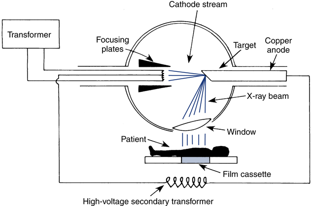
X-rays are electromagnetic waves that radiate from a tube through which an electric current has been passed. The tube is made of a cathode that is attached to a low-voltage electron source (transformer). The end of the cathode wire is inside the vacuum-sealed tube, and as electrons flow through the wire, they are “boiled off,” accelerate across a short gap, and strike a positively charged tungsten plate called the anode. The electrons coming off the cathode wire are focused to hit a small area on the anode. This area is called the target.


On striking the target, the electrons undergo physical changes that result in the emission of x-rays. The origins of the name x-rays are rather remarkable. Wilhelm Roentgen, a physicist from the 19th century, who is unanimously credited for the discovery of x-rays, was experimenting with various types of electromagnetic radiation. He called a particular type of radiation that he was studying x-rays, “x” for the unknown. Since then, the electromagnetic radiation in general and x-rays in particular have been extensively studied, but the name x-rays still persists, although in some countries they are referred to as Roentgen radiation. These x-rays are emitted in all directions, but because of the construction of the tube, only the few that escape through the window are actually used; the rest are absorbed harmlessly into the wall of the x-ray machine (Fig. 10-1). X-rays are not reflected like light rays but penetrate most matter. Their ability to penetrate matter depends on the density of the matter. Dense objects, such as bone, absorb more x-rays (allow less penetration) than air-filled objects, such as lung tissue.


A chest radiograph is generated by placing a sheet of film next to the patient’s thorax opposite the x-ray tube. The x-ray machine emits x-rays, which pass through the patient and are absorbed by the film inversely proportional to the density of the tissue through which they pass. X-rays that pass through low-density (air-filled) tissue strike the film in great numbers and turn it black (radiolucent). Radiolucent areas on the chest radiograph are seen as dark shadows. X-rays that strike bone are partially absorbed; therefore, fewer x-rays strike the film, and there is less darkening of the corresponding area on the radiograph (radiopaque). Radiopaque areas are seen as white shadows on the film. The whole concept of “film” has recently changed with the advent of digital image processing.


In the past, a sheet of film that had the image of the x-rays would have to be “developed” (much like the old film photography) and then viewed by placing it on a box that would provide a background light in a dark room. Instead, we now use cassettes that acquire the images digitally and then transfer that digital image of the x-ray onto a computer database to be viewed electronically or placed in the patient’s electronic medical record. After transfer, the cassette that was just used in the last x-ray production is ready to record a new image, much like a modern memory card can store new images after the old ones have been erased or transferred. Just as with digital still photography, digital x-ray imaging provides many tools for the interpreter (magnification, change of contrast, inversion, to name a few) that were not available in the old-fashioned films. One might argue that the use of the term film is now outdated because the actual film is not used in either production or viewing of the x-ray images. Despite this conceptual change, many clinicians will continue to use the term film to describe digital x-ray images. We will perpetuate this misnomer throughout the chapter and will call the film the cassette that acquires the x-ray images as well as the computer that produces the images.


One major flaw of all radiographs that a clinician needs to remember is that they present a two-dimensional view of a three-dimensional object. Structures on the same horizontal level produce the same shadow on the image whether they are inside or outside of the body. For example, a coin taped to the outside of the patient’s chest (either in the front or back) will produce the same shadow as a round lung mass—hence, many round-shaped lung masses (or nodules) are called coin lesions. Similarly, nipple shadows often cause concern because they cannot be easily distinguished from lesions originating from lung parenchyma.


Four distinct densities recognized on radiographs are that of bone, which is very dense; water, which is less dense; fat, which is mildly radiolucent; and air, which is very radiolucent. Most tissues in the body have a characteristic density based on the mixture of these materials. The anatomy of the chest makes radiographs extremely useful for studying diseases of the chest. The contrast between the bony structures of the chest, the heart, the vascular structures of the mediastinum, and the diaphragm, which appear radiopaque on radiographs, and the lungs, which appear radiolucent, allows for easy recognition of these structures on the image and various diseases that affect them. For a comparison, muscles in the thigh are uniformly radiolucent, and there is not much contrast between the various parts of the thigh when radiographs are taken. This makes radiographs of the thigh not helpful, unless one is looking for bony fractures or air that has been introduced from infection or a penetrating wound.


X-rays leave the x-ray tube from a single point and scatter so that they cover the whole x-ray film. This leads to more magnification of shadows on the film if the patient is close to the x-ray tube and less magnification if the patient is not close to the x-ray source. This concept can be demonstrated easily by placing your hand below a lamp and observing the shadow created on the surface below. The shadow becomes smaller and sharper as your hand is moved away from the light source and closer to the surface. The concept of magnification of shadows farther away from the film will become important later in this chapter when we discuss various x-ray techniques. The radiation scatter is important because individuals within the 6 feet radius from the x-ray source are exposed to significant radiation. Radiation safety will be discussed in more detail at the end of the chapter.


Indications for the Chest Radiograph Examination


The ability to “see inside” the body with the use of radiographs has proved to be of great benefit, especially when assessing the contents of the chest. Production of the chest radiograph has become one of the most popular and important procedures performed in the hospital. It can be used in the following ways:


Although the chest radiograph provides important information about the status of the lungs, obtaining and interpreting the image must never delay fundamental treatment of the patient with obvious signs of hypoxia. In most situations, when the members of the health care team are well trained and work together, a chest image can be obtained without interrupting assessment and treatment.


Although only the physician can order a chest radiograph, the respiratory therapist (RT) may want to suggest to the attending physician that a chest image may be needed in certain circumstances. For example, an undiagnosed pneumothorax may suddenly cause deterioration of a mechanically ventilated patient. In the setting of a tension pneumothorax (discussed in detail later in this chapter), there may not be time even for an urgent radiograph, and treatment may have to be started solely on clinical grounds. However, in a less urgent situation, a portable chest film may be very helpful in confirming the suspected pneumothorax. The RT is often at the bedside of the mechanically ventilated patient and may be the first person to see the signs consistent with a pneumothorax, or another potentially serious complication, and would be the first to recognize the need for an urgent chest radiograph. For this reason, all RTs should be familiar with the clinical indications for a chest radiograph (Box 10-1).


Box 10-1   Clinical Indications for the Chest Radiograph


Symptoms


Radiographic Views


Standard and Special Views


The standard chest radiographs are taken in two directions: posteroanterior and lateral views. First, with the patient standing upright with the back to the x-ray tube, the anterior thorax is pressed against a metal cassette containing the film, and the patient’s arms are positioned out of the way. The patient is instructed to take a deep breath and hold it just before the radiograph is taken. The x-ray beam leaves the source, strikes the patient’s posterior chest, moves through the chest, exits through the front (anterior), and then strikes the film. This is called a posteroanterior (PA) view because the beam moves from posterior to anterior. The heart is in the anterior half of the thorax, so there is less cardiac magnification with a PA view. The patient is then turned sideways, and a lateral or side view is obtained. Generally, a left lateral view (left side against the cassette) is preferred. The left lateral view provides less cardiac magnification (as explained earlier, the proximity of the heart is the cause of lesser magnification) than the right lateral view. On a lateral image, the shadows of the left and right lung are often superimposed and cannot be distinguished. For this reason, the lateral image is often obtained with the patient slightly oblique (about 5 degrees) to the image (an oblique view), to allow easier identification of the individual lung shadows.


Other views are sometimes obtained to elucidate special problems. A lateral decubitus view is taken with the patient lying on the right or left side to see whether free fluid (pleural fluid) is present in the chest. As little as 50 to 100 mL of pleural fluid can be detected with the lateral decubitus view. This view is also helpful in the identification of pneumothorax. Air tends to rise and water tends to fall; therefore, patients with a suspected pneumothorax should be placed on the opposite side for radiologic examination, and patients with suspected pleural fluid should be placed on the same side as the suspected disease.


Projections made at approximately a 45-degree tube angulation from below, referred to as an apical lordotic view, are sometimes required for a closer look at the right middle lobe or the top (apical region) of the lung. When the tube is angled upward, the shadows of the clavicles are projected above the thorax, and the tops of the lungs are much more easily visible.


Oblique views are helpful in delineating a pulmonary or mediastinal lesion from the structures that become superimposed on those lesions on the PA and lateral views (review the limitations of radiographs as two-dimensional views of a three-dimensional objects discussed earlier). Oblique views are often obtained to help localize an abnormality. In this view, the patient is turned 45 degrees to either the right or left, with the anterolateral portion of the chest against the film.


Although chest radiographs are usually taken with the patient at full inspiration, an expiratory view can be helpful in certain situations. For example, a small pneumothorax can be difficult or impossible to detect in a routine inspiratory image. As the patient exhales, however, the lung volume is reduced, whereas the pleural air volume remains the same. The pneumothorax now occupies a greater percentage of the thoracic volume and therefore stands out more. In addition, the lung is denser in the expiratory position, and the contrast allows for the air density within the pleural space to be more easily visualized.


With the advance of the technology, CT scans are now readily available, easy to obtain, and able to provide information about thoracic structures that is above and beyond what can be obtained by a variety of special radiographic views. In many instances, these special views have become obsolete and have retained only teaching and historical value.


Portable Chest Image (Anteroposterior View)


Patients in intensive care units are too sick to be transported to the radiology department for a standard PA view. In this instance, a portable radiograph machine is brought to the patient’s bedside and positioned in front of the patient. The film cassette is placed carefully behind the patient’s back. Thus, the x-ray beam moves from front to back (anterior to posterior), generating an anteroposterior (AP) view instead of the usual PA view. The distance from the patient to the beam’s origin is typically 4 feet in these conditions, so there is more magnification artifact than with a regular PA view.


Interpreting an AP chest radiograph presents a special challenge because often it is not centered, is rotated, is either overexposed or underexposed, or is not taken when the patient is in full inspiration. There may be many extrathoracic shadows superimposed on the film. These extra shadows include bedding, gowns, electrocardiogram (ECG) leads, and tubing. The clinician has to be able to read the film accurately despite these confounding factors.


AP portable films are obtained to evaluate lung status, to gain information on how well lines and tubing are positioned, and to see the results of invasive therapeutic maneuvers. Some of the lines and tubes needing evaluation are discussed later in the chapter under Postprocedure Chest Radiograph Evaluation.


Evaluation of the Chest Radiograph


This section introduces the basic principles of chest radiograph evaluation. Interpreting chest images is a skill obtained only through hours of dedicated practice. The beginner is encouraged to view chest images initially with the help of qualified experts.


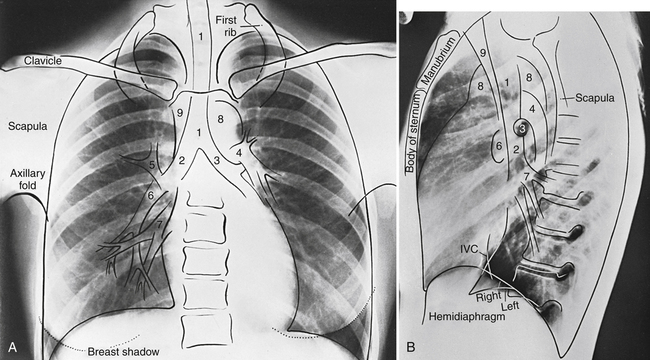
Familiarity with the anatomic landmarks seen on normal chest images is extremely helpful in learning to recognize abnormalities. Figure 10-2 identifies the important landmarks on a normal PA chest radiograph.


Systematic Approach to the Chest Radiograph


The first step in evaluating the chest radiograph is to determine the technical quality of the image. The adequacy of exposure can be judged by looking at the vertebral bodies. The clinician should be able to just about visualize the vertebral bodies through the cardiac shadow. If the vertebral bodies are easily seen, the image is probably overexposed, and the lungs will appear black. Underexposure makes identification of the vertebral bodies more difficult, and the lung fields appear whiter than on a properly exposed image. The pulmonary vascularity and some pulmonary abnormalities may be misinterpreted with overexposure or underexposure.


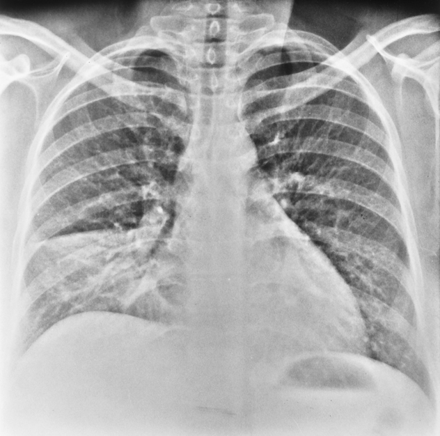
The chest radiograph should be evaluated to make sure that the patient was not rotated when the chest image was obtained. If the patient is rotated, uniform exposure of both lungs will not be obtained, and one side of the image will be darker than the other. The shadows of the heart and other mediastinal structures may also appear enlarged if the patient is rotated. Patient rotation is assessed by identifying the relationship of the spinous processes of the vertebral column to the medial ends of the clavicles (Fig. 10-3). The spinous processes should be centered between the ends of the clavicles and directly behind the tracheal air shadow. If the medial end of one clavicle appears closer to the spine, the patient probably was rotated.


Finally, the degree of the patient’s inspiratory effort is evaluated by counting the posterior ribs visible above the diaphragm. On a PA image, 10 ribs indicate a good inspiratory effort. A poor inspiratory effort may cause the heart to appear abnormally enlarged and increase the density of the lung fields so that they appear too white to allow detection of certain lung abnormalities.


Interpretation


Interpretation of the chest image requires a complete understanding of the x-ray principles introduced at the beginning of this chapter. The clinician must remember that x-ray penetration of structures is inversely proportional to the density of the structure, and thus the greater the density, the less the penetration. X-rays that do not penetrate fully are absorbed, resulting in less exposure of the film and the casting of a white shadow on the image.


Normal lung tissue has a low density (air density) so that few x-rays are absorbed, and normal lung fields appear as dark shadows on the chest radiograph. If an area of the lung consolidates (increases in density) because of pneumonia, tumor, or collapse, that area will absorb more x-rays and appear as a white patch on the film. Abnormalities that decrease lung tissue density, such as cavities and blebs, absorb fewer x-rays and result in darker areas on the film.


The heart, diaphragm, and major blood vessels are considered to have the density of water. Water is denser than air, and water densities result in less exposure and therefore whitish-gray shadows on the chest radiograph. The heart, diaphragm, and major blood vessels rarely alter in density but may change in size, shape, and position. Evaluation of the shadows produced on the chest radiograph by these structures allows a clear view of any deviation from normal in position or size.


It is important to note that the lung shadow on a normal chest radiograph is not uniformly black. The pulmonary vessels that are perpendicular to the x-ray plane give round shadows, and the vessels that are parallel to the plane give tubular shadows. So the normal lung will appear “peppered” with dots and lines that represent pulmonary vasculature. This appearance is sometimes called normal lung architecture. As a result of the absence of the lung vasculature, blebs and the air contained in pneumothorax do not have this particular lung architecture appearance, which makes it easier to distinguish them from the normal lung tissue.


The structures in the chest with the greatest density are the bones, including the ribs, clavicles, scapulae, and vertebrae. They are seen on the radiograph as white shadows. Fractures and changes in position and density of bones may be evaluated with a chest radiograph. It should be obtained to evaluate the bony structures of the chest when the patient’s history or physical examination suggests chest trauma.


Identification of the abnormalities visible on the chest radiograph requires a systematic review of all the structures shown on it. The sequence in which the structures are evaluated is not important as long as all are included. Many experts encourage beginners to develop a habit of evaluating the bony structures and peripheral areas of the radiograph first. This helps prevent overlooking subtle but important abnormalities in the less conspicuous areas of the radiograph. Once the peripheral soft tissues and bony structures have been viewed, the lung, mediastinum, heart, and diaphragms are inspected carefully. A system using the alphabet—A to Z—has been recommended to remind the examiner which parts of the chest image to study. This system, starting with A for airway, B for bones, C for cardiac shadow, and so forth, may prove useful in organizing the approach to reading the chest radiograph. An alternative approach is to follow a comfortable pathway around the chest radiograph. The major goal is to use the same method of complete review in every individual case.


The ability to localize abnormalities within the thorax is aided by special radiographic signs. Two of the most important radiographic signs are the silhouette sign and the air bronchogram.


Silhouette Sign


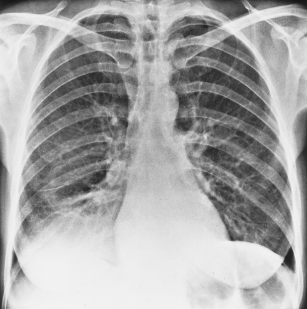
The silhouette sign is useful primarily in determining whether a pulmonary infiltrate is in anatomic contact with another thoracic structure. Normally, the significant difference in density between two adjoining structures will sharply delineate their borders. This allows a person viewing the chest radiograph to see the heart border, the aortic knob, and the diaphragm shadows on the background of radiolucent lung—a natural contrast between the thoracic tissues that makes the chest radiograph a great diagnostic tool (see comparison to thigh radiograph earlier in this chapter). If the lung tissue in contact with either heart border or sections of diaphragm becomes consolidated, the contrast in densities is lost, and the corresponding heart or diaphragm border is blurred (Fig. 10-4; see Fig. 10-3). This phenomenon is called the silhouette sign.


The heart is located in the anterior thorax, and any infiltrate that obliterates the heart border must also be located in the anterior segments of the lungs (lingula or the right middle lobe). Infiltrates that appear to overlap the heart border on the image but do not affect its sharpness are located in posterior segments and are not in anatomic contact with the heart. An infiltrate in the mid-lung zone on a chest radiograph may be located anteriorly or posteriorly, and the silhouette sign often allows a better localization (a lobe, rather than more vague “zone”) of the infiltrate. Infiltrates that create a silhouette sign by blurring the diaphragm border are thought to be in the lower lobes.


Air Bronchogram


The presence of air bronchograms is useful in determining whether an abnormality seen on the radiograph is located within lung tissue. Intrapulmonary bronchi are not normally visible on chest images because they contain air and are surrounded by air-filled alveoli. Bronchi surrounded by consolidated alveoli are visible because the air within their lumina will stand out in contrast to the surrounding consolidation and fluid. In this situation, the bronchi are seen as linear branching air shadows, signifying that the lesion is within lung tissue. Diseases that both consolidate lung tissue and fill the airways will not produce air bronchograms. Therefore, the presence of an air bronchogram confirms intrapulmonary disease, whereas the absence of an air bronchogram does not rule it out.


Clinical and Radiographic Findings in Lung Diseases


This section reviews the radiographic findings typical of the more common respiratory disorders. Familiarity with this information is helpful in the interpretation of the chest radiograph. In addition, this section presents the clinical findings typically associated with the different pathologic abnormalities described. In most cases, the most efficient and accurate assessment is achieved when clinical and radiographic findings are used together. The following categories of chest disorders are presented:


Jun 18, 2016 | Posted by in RESPIRATORY | Comments Off on Chest Imaging

Full access? Get Clinical Tree

Get Clinical Tree app for offline access