Catheter Tracking and Devices
Harald H. Quick
Several attributes make magnetic resonance imaging (MRI) attractive for guidance of intravascular therapeutic procedures, including high soft tissue contrast, imaging in arbitrary oblique planes, lack of ionizing radiation, and the ability to provide functional information, such as flow velocity or flow volume per unit time, in conjunction with morphologic information. For MR guidance of vascular interventions to be safe, the interventionist must be able to visualize catheters and guidewires relative to the vascular system and surrounding tissues. Several approaches for rendering instruments visible in an MR environment have been developed, including both passive and active techniques. Passive techniques depend on contrast agents or susceptibility artifacts that enhance the appearance of the catheter in the image itself, whereas active techniques rely on supplemental hardware built into the catheter, such as a radiofrequency (RF) coil. In addition, the ability to introduce an RF coil mounted on a catheter presents the opportunity to obtain high-resolution images of the vessel wall. These images can provide the capability to distinguish and identify various plaque components. The additional capabilities of MRI could potentially open up new applications within the purview of vascular interventions beyond those currently performed under x-ray fluoroscopic guidance.
This chapter reviews the technical and clinical requirements for MR-compatible interventional instruments. The basic techniques for MR-guided instrument visualization are demonstrated with current examples from preclinical cardiovascular interventions such as MR-guided guidewire and catheter tracking, aortic stent grafting, and MR-guided transarterial aortic valve implantation (TAVI). Issues of MR safety related to interventional devices in an MR environment are discussed.
INTERVENTIONAL DEVICE VISUALIZATION
Prerequisite to the safe and successful performance of vascular interventions with MRI is not only the collection of relevant anatomic information, but also the reliable visualization of catheters and guidewires in relation to the surrounding tissue morphology. In contrast to ultrasound, x-ray fluoroscopy, or computed tomography (CT), visualization of interventional instruments in MRI has proven to be difficult.
The technique used to render vascular instruments visible in MRI would ideally be characterized by high spatial and temporal resolution. It should also provide a high-contrast instrument signature, making it easy to pick out the instrument in the MR image. Several approaches have been developed for depicting vascular instruments in an MR environment. They can be broadly grouped into two categories: Passive and active visualization. The passive techniques are familiar from ultrasound, x-ray fluoroscopy, and CT. The material properties of the instrument are manipulated so that the instrument appears with sufficient contrast in the image itself. No additional hardware or instrument modi-fications are required. The active techniques rely on additional hardware and postprocessing to achieve instrument localization.
PASSIVE INSTRUMENT VISUALIZATION
Two approaches to passive catheter guidance exist. The first is to alter the blood signal relative to the catheter signal. This can be achieved with administration of a vascular contrast agent. Gadolinium diethylenetriaminepentaacetate (DTPA) allows the acquisition of high-resolution MR angiograms that could be used for tracking vascular instruments relative to arterial morphologic background “road maps.” However, commercially available contrast agents rapidly leak out of the vascular space, resulting in increased signal in the background tissues. This alters the signal characteristics of the
target vessel and potentially reduces catheter visualization. Intravascular MR contrast agents have a prolonged intra-vascular presence but equally opacify both arteries and veins (1,2). Strategies for reducing venous opacification have been explored by using contrast agents based on superparamag-netic iron oxides with both T1– and T2-shortening effects (3). By filling the catheter with a Gd-based contrast agent, both vascular system and instruments can be visualized separately with a double-echo gradient-echo sequence. The image based on the short echo renders both the vasculature and the catheter bright, whereas the image based on the long echotime (TE) renders only the catheter bright. The catheter-only image (second echo) can be threshold and overlaid in color on the vascular image (first echo) (3).
target vessel and potentially reduces catheter visualization. Intravascular MR contrast agents have a prolonged intra-vascular presence but equally opacify both arteries and veins (1,2). Strategies for reducing venous opacification have been explored by using contrast agents based on superparamag-netic iron oxides with both T1– and T2-shortening effects (3). By filling the catheter with a Gd-based contrast agent, both vascular system and instruments can be visualized separately with a double-echo gradient-echo sequence. The image based on the short echo renders both the vasculature and the catheter bright, whereas the image based on the long echotime (TE) renders only the catheter bright. The catheter-only image (second echo) can be threshold and overlaid in color on the vascular image (first echo) (3).
The second approach to passive catheter guidance involves altering the catheter signal relative to the blood signal. Instruments can be filled with contrast-doped solution, shortening the relaxation time. Imaging is accomplished by using a short repetition time (TR)/short (TE) pulse sequence along with a high flip angle, achieving a catheter image that is bright relative to the background. The slice thickness is generally limited, however, because the instrument rapidly disappears as a result of partial voluming as the thickness is increased (4). Rather than filling the lumen of the catheter with liquid contrast solution, another approach is to treat the surface of the catheter with Gd3+ ions (5). As a consequence, the T1 of blood in the immediate vicinity of the catheter is shortened, rendering the catheter visible.
A different approach to achieving adequate catheter contrast is based on enhancing the inherent signal void (i.e., negative contrast) of an instrument as it displaces spins during insertion. Differences in magnetic susceptibility can be used to create large, local losses in signal as a result of intravoxel dephasing (6,7 and 8). Unfortunately, these signal losses are most often accompanied by geometric distortion of the underlying vascular anatomy. In addition, the effect is highly dependent on several factors, including field strength, pulse sequence parameters, and device orientation within the magnetic field. These dependences prevent a consistent portrayal of instruments. A useful approach has been to incorporate multiple rings of paramagnetic dysprosium oxide (Dy2O3) along the catheter tip, allowing the catheter to be consistently visualized independent of orientation (8).
The following sections provide three current examples for the development of MR-compatible instrumentation that make use of passive visualization techniques.
Guidewires
In the recent past, a number of MR-guided vascular interventions have been performed, evaluating MR-compatible and MR-safe instruments that make use of passive visualization techniques. As one of the most important basic instruments, vascular guidewires have been developed by different groups that are based on glass fiber or polyetheretherketone (PEEK)-fiber reinforced plastics (9,10,11,12,13,14 and 15). The rationale of such fiber reinforcement is to provide mechanical stiffness of the rather small-diameter instruments, and at the same time to obviate the need for metallic cores and wires that are common in x-ray guidewires and which pose a potential safety risk in MRI. An example of a PEEK-reinforced guidewire is shown in Figure 36.1. Passive guidewire visualization is often hampered by the rather small diameter (below 1 mm) of the flexible vascular instruments. To increase instrument visibility, magnetic susceptibility markers have been integrated into the design at defined positions relative to the instrument tip. Such markers provide small signal voids due to susceptibility artifacts at defined positions that facilitate instrument visualization (Figs. 36.1 and 36.2). MR-compatible guidewires have successfully been tested in preclinical animal experiments (11,12,13,14 and 15) as well as most recently in the first applications in humans (16). It remains to be tested and it will depend on the specific applications whether such passively visualized MR-compatible guidewires will provide sufficient mechanical stiffness, long-term stability, and image visibility to substitute standard guidewires that are used in x-ray guided interventions.
Aortic Stent Grafting
Beyond the development of vascular guidewires, more application-specific instrumentation has been investigated for its potential use in MR-guided interventions. In a study in 2006 (17), commercially available thoracic aortic stent grafts have been systematically investigated regarding their MR compatibility and artifact behavior. Furthermore, the associated delivery catheters also have been tested toward MR compatibility and MR safety. From an initially tested group of six different stent grafts and delivery devices, just one combination of stent graft and device, the GORE TAG aortic stent graft has been tested MR-compatible for further experimental evaluation in an in vivo study on pigs (18) (Fig. 36.3). The stent graft with its nitinol mesh showed only mild susceptibility artifacts which indicates that no ferromagnetic wires or components have been used in the production. Furthermore, the large-caliber (18F) catheter delivery device does not contain any metal braidings or metallic components that would render this specific device potentially MR unsafe. Aortic stent grafting provides an excellent example for the strength of MR guidance as well as for the advantages of passive instrument visualization. Large-diameter instruments guided within the large-diameter aorta can robustly be visualized using a fast steady-state free precession (SSFP, TrueFISP, balanced FFE, Fiesta, etc.) sequence. With this sequence type, passive instrument visualization provides good instrument-to-background contrast featuring bright blood and dark instrument profiles with a high frame rate (Fig. 36.4) (18).
Transarterial Aortic Valve Implantation
Building on similar features of passive instrument visualization, a most recent study has investigated the possibility to guide the rather new clinical procedure of TAVI under MRI (19). Again, MR compatibility of the associated devices is one of the preconditions for a potential translation from animal models into the clinical arena. While the tested aortic valve prosthesis (CoreValve, Medtronic) has been tested MR compatible, the associated delivery device showed ferromagnetic attraction as well as severe artifacts due to ferromagnetic components and metallic braidings integrated along the delivery catheter shaft (19) (Fig. 36.5). Accordingly, the catheter delivery device has been redesigned without ferromagnetic components and without metal braiding to render the instrument MR compatible. Figure 36.5 shows a side-by-side comparison of the original delivery catheter providing strong artifacts and the redesigned MR-compatible delivery catheter showing no artifacts. This catheter and valve combination has then been further investigated in an in vivo study in pigs (20). Passive instrument visualization with real-time TrueFISP sequence here provided excellent MR guidance of the TAVI procedure (Fig. 36.6).
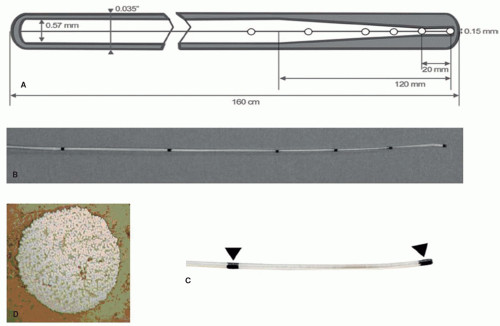 Figure 36.1. Schematic illustration, photography, and cross-section of a PEEK-based MR-safe 0.035-inch guidewire. The schematic illustration depicts the structure and measures of the 160-cm long guidewire (A). The 0.57-mm core fiber-reinforced PEEK compound (white central zone) is tapered toward the 120-mm long flexible distal part with a minimal diameter of 0.15 mm at the 20-mm long floppy and thereby atraumatic tip of the wire. The guidewire has a polyurethane polymer jacket (gray peripheral zone) and a hydrophilic coating, yielding a final diameter of 0.035 inches along the whole guidewire axis. Passive MR markings are positioned at the distal wire (white circles). Photos show the flexible distal part of the guidewire (B) and a magnification of the most distal two MR-markers (arrows, C). A photograph of a bright field microscopy (D) demonstrates the PEEK/fiberglass core compound in cross-section. (Courtesy of Sebastian Kos, MD, and Deniz Bilecen, PhD, University of Basel, Switzerland.) |
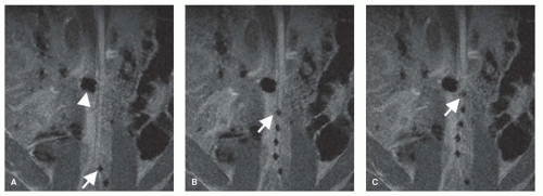 Figure 36.2. Passive instrument visualization of a PEEK-based MR-safe guidewire (see also Fig. 36.1). MR image-guided advancement of the guidewire into the abdominal aorta of a pig. The distal end of the guidewire can be depicted in the real-time MR images due to its markings along the guidewire structure showing as a line of dark signal spots. The guidewire is advanced from the left iliac artery (A) into the abdominal aorta of the pig (B,C). Arrows in (A–C) point toward the guidewire tip. The larger signal void in (A–C) (marked with arrowhead in (A)) shows the image artifact resulting from a metallic stent placed in the right renal artery of the pig. (Courtesy of Sebastian Kos, MD, and Deniz Bilecen, PhD, University of Basel, Switzerland.) |
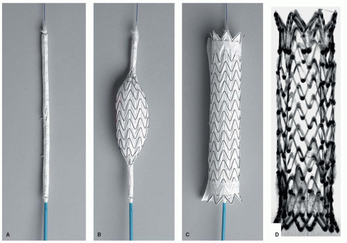 Figure 36.3. Commercially available GORE TAG thoracic aortic stent graft for catheter-based therapy of thoracic aortic dissection. A: The stent graft loaded on the distal end of the 18F polyurethane delivery catheter. B: Partly released stent graft. C: Fully released nitinol-based, membrane-covered stent graft. D: Corresponding minimum intensity projection from a high-resolution T1-weighted 3D FLASH sequence. The FLASH sequence allows for detailed evaluation of the lumen and surroundings of the stent graft indicating no severe imaging artifacts thus serving as reference for MR-compatibility testing. |
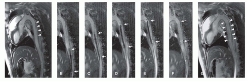 Figure 36.4. MR image-guided thoracic aortic stent graft deployment in a pig model of aortic dissection. A: Preinterventional high-resolution MRI (cine-TrueFISP retro) in parasagittal orientation showing the dissection flap (arrowheads) in the proximal descending thoracic aorta. One of twenty acquired frames per RR-interval is shown. B-F: Safe advancement of the stent graft delivery system (arrows) up to the level of the dissection under rtMRI guidance. G: The correct stent graft position (arrowheads) is confirmed immediately after stent graft deployment showing complete coverage of the dissection. |
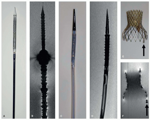 Figure 36.5. Photograph of the commercially available self-expandable nitinol-based Medtronic CoreValve bioprosthesis and its original delivery catheter for image-guided transarterial aortic valve implantation (TAVI). Photography (A) and high-resolution 3D FLASH image (B) of the original delivery catheter showing a side-by-side correlation of individual device details and according imaging artifacts in MRI. The original device here (B) shows severe imaging artifacts due to ferromagnetic catheter components as well as due to mechanical stability reinforcing metal braiding in the catheter shaft. The redesigned delivery catheter (C) was developed while not using metallic components or metallic braiding, and thus shows absolutely no artifacts in the highresolution 3D FLASH images (D). The nitinol-based aortic valve and redesigned delivery device can thus be considered MR safe. E: Photography of the nitinol stent frame with the aortic valve. F: High-resolution 3D FLASH sequence revealing slight MR signal attenuation within the metallic stent frame and excellent correlation in showing the eyelet (arrows) at the outflow tract of the stents. |
ACTIVE INSTRUMENT VISUALIZATION
Several of the active tracking techniques that have been demonstrated to be suitable for vascular interventions involve the incorporation of an RF coil into the instrument itself. MR tracking relies on the incorporation of a miniature sole-noidal coil into the instrument (21,22,23,24 and 25). The coil is connected to the scanner via a thin coaxial cable passing through the catheter and provides a robust signal, identifying the instrument location with high contrast. Early tracking catheter
designs incorporated an RF coil on the tip of interventional instruments (Fig. 36.7A,B), thus the tip could be visualized with high contrast and high temporal resolution in three dimensions (22). The actively available three-dimensional (3D) spatial coordinates could also be used to steer the actual imaging plane with the instrument tip, allowing for two-dimensional (2D) imaging updates at the exact location of the coil, with corresponding depiction of the surrounding anatomy. More current setups for catheter tip tracking now combine fast updates of the catheter position with real-time imaging sequences, such that real-time imaging is always performed at the current catheter position (26,27 and 28). Up to three tracking coils implemented into the catheter over several centimeters enable to link the slice position and orientation to the distal end of the instrument (26,27). The interventionist can thus assess the current interventional situation in real time. Practical considerations, however, suggest that the entire instrument needs to be visualized, rather than only the instrument tip.
designs incorporated an RF coil on the tip of interventional instruments (Fig. 36.7A,B), thus the tip could be visualized with high contrast and high temporal resolution in three dimensions (22). The actively available three-dimensional (3D) spatial coordinates could also be used to steer the actual imaging plane with the instrument tip, allowing for two-dimensional (2D) imaging updates at the exact location of the coil, with corresponding depiction of the surrounding anatomy. More current setups for catheter tip tracking now combine fast updates of the catheter position with real-time imaging sequences, such that real-time imaging is always performed at the current catheter position (26,27 and 28). Up to three tracking coils implemented into the catheter over several centimeters enable to link the slice position and orientation to the distal end of the instrument (26,27). The interventionist can thus assess the current interventional situation in real time. Practical considerations, however, suggest that the entire instrument needs to be visualized, rather than only the instrument tip.
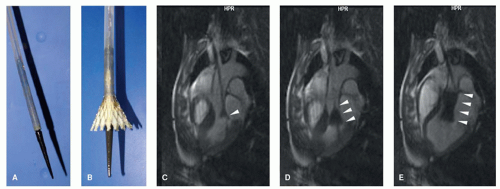 Figure 36.6. A: Distal end of the TAVI catheter delivery device with the loaded and covered stent valve. B: Partly released nitinol stent valve that can mechanically be released by slowly retracting the catheter sheath. C-E: Real-time TrueFISP images of MR-guided Core Valve deployment in vivo in a pig. Arrowheads in (C-E) show successive stent release. |
One way to obtain the curvature information missing with the MR tracking technique is to elongate the RF coil in the instrument. Magnetically coupled antennas with reduced signal penetration depth can be used. These are the traditional looped antennas of MR, familiar from all surface coils: The coils are simply wound very thin and extended over a length of several centimeters (29,30 and 31). These antennas generate an outline of very limited extent, which sharply delineates the instrument. The acquisition of a conventional MR image with these antennas leads to an outline or “profile” of the instrument as a result of the localized sensitivity of the coils, thus the designation “MR profiling” (Fig. 36.7C,D) (30,31).
Another group of RF antennas suitable for integration into small-diameter vascular instruments are the electrically coupled loopless antennas (dipoles or stubs) (32,33). Such antennas provide a relatively homogeneous signal profile along the whole instrument. Signal sensitivity here is directed toward the outside of the antenna, providing a signal beyond the constraints of the instrument. This might be advantageous for simultaneously displaying the immediate anatomic surrounding when tracking the instrument; however, this signal characteristic hampers sharp delineation of the instrument. In addition, the signal in early prototypes of dipole antennas has been inherently faint at the antenna tip, which has led to insufficient instrument tip visibility.
In previous experimental studies that explored the potential for performing MR-guided cardiovascular interventions with actively visualized instruments, the instruments were tracked on preacquired, high-quality contrast-enhanced vascular road maps (24,25,30). With this strategy, the time-consuming acquisition of vascular road maps could be performed before moving on to the acquisition of real-time updates for continuous display of the instrument position. Although vascular road map and real-time instrument tracking were thus independent from each other, such strategies had obvious drawbacks: The anatomic road map did not always represent the current anatomic situation during the course of an intervention. Gross movements of the patient or cardiac and breathing motion sometimes led to misregistrations between the anatomic road map and the instrument position.
The drawbacks of preinterventional road map acquisition strategies can be overcome by the use of fast imaging techniques with steady-state free precession (SSFP), also referred to as TrueFISP, balanced FFE, Fiesta, and so forth. Such sequences, in general, offer high image acquisition speed, signal-to-noise ratio (SNR), contrast-to-noise ratio (CNR), and furthermore, contrast characteristics that render vessels hyperintense, even without the administration of a contrast agent, making them attractive for the guidance of interventional MRA. Current setups for performing MR-guided cardiovascular interventions are based on the combination of actively visualized instruments with real-time
TrueFISP imaging (27,34,35). Figure 36.8 shows a schematic example of an interventional real-time imaging setup that combines active instrument visualization and TrueFISP imaging to enable real-time image acquisition, reconstruction, fusion, and display with multiple RF receiver channels for the simultaneous and independent display of actively visualized instruments and vascular morphology (34).
TrueFISP imaging (27,34,35). Figure 36.8 shows a schematic example of an interventional real-time imaging setup that combines active instrument visualization and TrueFISP imaging to enable real-time image acquisition, reconstruction, fusion, and display with multiple RF receiver channels for the simultaneous and independent display of actively visualized instruments and vascular morphology (34).
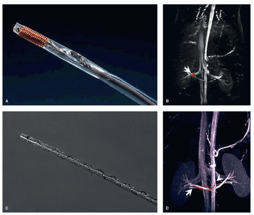 Figure 36.7. Active instrument visualization through implementation of radiofrequency (RF) coils into vascular instruments. A: “Tip-tracking” guidewire. The integrated solenoid RF coil at the instrument tip provides localized signal that can be used to superimpose the tip position in color (red cross) onto a previously acquired road map (arrow) (B), or to steer the position of the imaging plane in real time, respectively. C: “Profiling” guidewire. The integrated elongated helical wound RF coil provides signal over the distal end of the instrument, resulting in a sharp signal “profile” of the tip and curvature of the instrument (red line between arrow and arrowhead) (D). B,D: In vivo results in pig experiments |
Figure 36.9A shows an example of a 6F 1-lumen catheter that has been equipped with a coiled dipole antenna in order to render the catheter visible during advancement in the aortic arch of a pig (Fig. 36.9B-D). Figure 36.10


Stay updated, free articles. Join our Telegram channel
Full access? Get Clinical Tree
